Perfect antireflection via negative refraction
Abstract
We suggest a geometrical framework to discuss the action of slabs of negatively refracting materials. We show that these slabs generate the same orbits as normal materials, but traced out in opposite directions. This property allows us to confirm that the action of any lossless multilayer can be optically cancelled by putting it together with the multilayer constructed as the inverted mirror image, with and reversed in sign.
keywords:
Negative refraction; Left-handed mediaPACS:
41.20.Jb; 42.70.Qs; 42.25.Gy; 78.20.CiIn the last years the notion of materials with both negative electrical permittivity and magnetic permeability is at the center of a lively and sometimes heated debate. This idea dates back to 1968, when Veselago [1] theoretically predicted that these remarkable materials would exhibit a number of unusual effects derived from the fact that in them the vectors () of a plane wave form a left-handed (LH) rather than a right-handed (RH) set. For this reason, he called them LH media.
The first feasible implementation of such materials was suggested by Pendry [2, 3], who also made the provocative (and criticized) prediction that they can also act as a perfect lens [4]. Inspired by these ideas, Smith et al [5] constructed an artificial medium (consisting of microstructured arrays of small metallic wires and split ring resonators) with the desired properties in the microwave regime. Since then, new samples have been prepared [6, 7] and several potential future applications have been speculated [8]. To prevent the significant losses of these metamaterials, Notomi [9] suggested that identical behaviors could be expected to occur in lossless photonic crystals. Many researchers are now exploring this interesting possibility [10, 11, 12].
One of the most interesting properties of these LH materials is a negative refraction at the interface with a RH medium. Although this has been challenged by some authors [13, 14], the seminal work of Shelby, Smith and Schultz [15], as well as other subsequent experiments using different systems [16, 17], have dispelled any doubt regarding the reality of negative refraction.
Most of the work reported in the recent literature has been focused on the behavior of the evanescent components. The emphasis on the near-field limit comes from the interest that these media evoke as perfect lenses to transfer images. In this Letter we adopt a different and simpler strategy and center our attention in the far-field, much in the standard transfer-matrix formalism employed when dealing with multilayers [18]. As we have recently put forward [19, 20], the action of the system can be conveniently viewed as a bilinear transformation on the unit disk. This geometrical setting allows us to characterize the slabs by the associated orbits. It turns out that these orbits are the same for LH and RH materials, but they are traced out in opposite directions. This leads to an intuitive understanding of an intriguing result obtained by Pendry and Ramakrishna [21] and rederived recently by Lakhtakia [22] and Ruppin [23]: a LH slab cancels an identical RH slab. Furthermore, a much wider class of cancellation will be confirmed using our approach. We stress that the transfer matrix solely relies on the linearity of the wave equation, so that our treatment applies to any kind of waves and can seed light into fields where the notion of bandgap materials is becoming more and more important, such as sound or water waves [24].
We start by considering the simple example of a plane parallel slab of thickness and refractive index , surrounded by two semi-infinite identical media (ambient, , and substrate, , respectively) of refractive index . For simplicity, all the media are assumed to be homogeneous, isotropic and lossless.
A monochromatic linearly polarized plane wave falls from the ambient making an angle with the normal to the first interface and with an amplitude . We consider as well another plane wave of the same frequency and polarization, and with amplitude , incident from the substrate at the same angle . The output fields in the ambient and the substrate will be denoted and , respectively.
The field amplitudes at each side of this RH slab are related by the linear relation
| (1) |
where the transfer matrix can be explicitly constructed as [25]
| (2) |
Here accounts for the interface between the media and and has the form
| (3) |
and being the Fresnel transmission and reflection coefficients for the interface.
The matrix describes the propagation through the layer and is given by
| (4) |
where is the slab phase thickness. The parameter is the wavelength in vacuo and is the refraction angle in the layer.
The overall transfer matrix results then
| (5) |
where and are the reflection and transmission coefficients for the slab:
in such a way that .
We are often interested in the transformation properties of field quotients rather than the fields themselves. Therefore, we introduce the complex numbers
| (7) |
for both ambient and substrate. Equation (1) defines a transformation on the complex plane , mapping the point into the point , according to
| (8) |
where and . The matrix element is always a imaginary number for a symmetric system (i.e., a system for which the reflection and transmission coefficients are the same whether light is incident on one side or on the opposite side). Equation (8) is a bilinear (or Möbius) transformation and one can check that the unit disk remains invariant under the slab action [19]. Henceforth we assume that no light strikes from the substrate and then we have and .
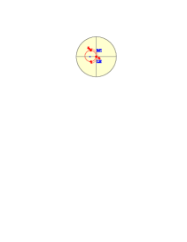
For this slab and the action in the unit disk leaves only one point invariant (fixed point) [26]. To picture how transforms into the concept of orbit is especially appropriate. Given the point , its orbit is the set of points obtained from by the action of the family of matrices representing a slab. This family can be generated, e.g., by varying continuously the thickness. One can then show that the orbits obtained are always (hyperbolic) circumferences centered at the fixed point and passing through the point . In Fig. 1 we have plotted a typical orbit as well as the transformed of the point for a slab of phase thickness of rad.
Let us consider the same slab, but of a LH medium, with negative refractive index . The same arguments used to assume a negative index lead to the conclusion that a positive wave impedance; i. e., , is the correct choice. This translates into the fact that the Fresnel equations remain valid provided the absolute values of and are used. On the other hand, it is well confirmed that the phase velocity is oppositely directed to the energy flow in these media.
All this together means that the interface matrices are the same as for the corresponding RH slab, while the layer matrices become complex conjugate. In other words, the matrix for this slab is
| (9) |
From this apparently innocuous formula, one can draw several nontrivial and interesting conclusions. First, we note that if we plug the matrix elements of in the bilinear action (8), the fixed point is the same, but the orbit is traced out in opposite direction. Therefore, in this geometrical picture, LH and RH materials have identical orbits, although for the former they are clockwise, while for the latter they are counterclockwise.
Let us now put together these RH and LH slabs. The resulting system is described by the product of the transfer matrices and , which, by virtue of Eq. (9), is precisely the identity. In consequence, we get a perfect antireflector with no phase change in transmission. This is quite intuitive from our unit-disk picture: the action of the global system consists of two successive identical rotations in opposite directions that cancel out.
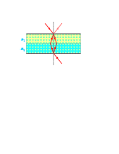
Alternatively, one can look at this problem by using the usual and intuitive method of adding multiply reflected and transmitted waves. Since in the interface between both slabs there is no reflected wave, the scheme of the energy flow is as indicated in Fig. 2. If we take the incident field of unit amplitude, the overall reflected field is
| (10) |
while the overall transmitted field is
| (11) |
which confirms the previous result.
The discussion so far admits a straightforward generalization for any multilayer. Indeed, let denote the transfer matrix of a system consisting of an arbitrary number of layers (some of them made of RH materials and some of LH materials), which can be constructed by a direct extension of (2). One can show that
| (12) |
with . Now we take the multilayer in the reverse order, which is represented by
| (13) |
Next we switch every RH layer to an identical LH layer and viceversa. The final system is thus described by , and one can check that [20]
| (14) |
In consequence, when both multilayers are put together they give the identity. This formalizes in a different framework the notion of “complementary media” introduced by Pendry and Ramakrishna [21]: any medium can be optically cancelled by an equal thickness of material constructed to be an inverted mirror image of the medium, with and reversed in sign. That is, complementary media cancel one another and become invisible (i.e., a perfect antireflector).
In summary, we have demonstrated another curious property of LH materials, which may be experimentally tested with the state of the art in this hot area of research. Although these results could have practical consequences, in our view they provide the first feasible implementation of how to build the inverse of a transfer matrix.
References
- [1] V. G. Veselago, Sov. Phys. Usp. 10 (1968) 509.
- [2] J. B. Pendry, A. J. Holden, W. J. Stewart, I. Youngs, Phys. Rev. Lett. 76 (1996) 4773.
- [3] J. B. Pendry, A. J. Holden, D. J. Robbins, W. J. Stewart, IEEE Trans. Microw. Theory Tech. 47 (1999) 2057.
- [4] J. B. Pendry, Phys. Rev. Lett. 85 (2000) 3966.
- [5] D. R. Smith, W. J. Padilla, D. C. Vier, S. C. Nemat-Nasser, S. Schultz, Phys. Rev. Lett. 84 (2000) 4184.
- [6] M. Bayindir, K. Aydin, E. Ozbay E, P. Markoš, C. M. Soukoulis, Appl. Phys. Lett. 81 (2002) 120.
- [7] K. Li, S. J. McLean, R. B. Gregor, C. G. Parazzoli, M. Tanielian, Appl. Phys. Lett. 82 (2003) 2535.
- [8] Optics Express, Focus issue: Negative Refraction and Metamaterials, 11 (2003) 639.
- [9] M. Notomi, Phys. Rev. B 62 (2000) 10696.
- [10] E. Cubukcu, K. Aydin, E. Ozbay, S. Foteinopolou, C. Soukoulis, Nature 423 (2003) 604.
- [11] A. Berrier, M. Mulot, M. Swillo, M. Qiu, L. Thylén, A. Talneau, S. Anand, Phys. Rev. Lett. 93 (2004) 073902.
- [12] R. Moussa, S. Foteinopoulou, L. Zhang, G. Tuttle, K. Guven, E. Ozbay, C. M. Soukoulis, Phys. Rev. B 71 (2005) 085106.
- [13] P. M. Valanju, R. M. Walser, A. P. Valanju, Phys. Rev. Lett. 88 (2002) 187401 .
- [14] A. L. Pokrovsky, A. L. Efros, Solid State Commun. 124 (2002) 283.
- [15] R. A. Shelby, D. R. Smith, S. Schultz, Science 292 (2001) 77.
- [16] C. G. Parazzoli, R. Gregor, K. Li, B. E. C. Koltenbach, M. Tanielian, Phys. Rev. Lett. 90 (2003) 107401.
- [17] A. A. Houck, J. B. Brock, I. L. Chuang, Phys. Rev. Lett. 90 (2003) 137401.
- [18] P. Yeh, Optical Waves in Layered Media, Wiley, New York, 1988.
- [19] T. Yonte, J. J. Monzón, L. L. Sánchez-Soto, J. F. Cariñena, C. López-Lacasta, J. Opt. Soc. Am. A 19 (2002) 603.
- [20] J. J. Monzón, T. Yonte, L. L. Sánchez-Soto, J. F. Cariñena, J. Opt. Soc. Am. A 19 (2002) 985.
- [21] J. B. Pendry, S. A. Ramakrishna, J. Phys.: Condens. Matter 15 (2003) 6345.
- [22] A. Lakhtakia, Int. J. Infrared Millim. Waves 23 (2002) 339; 24 (2003) 19.
- [23] R. Ruppin, J. Phys.: Condens. Matter 16 (2004) 8807.
- [24] A complete and up-to-date bibliography on the subject can be found at http://home.earthlink.net/~jpdowling/pbgbib.html
- [25] R. M. A. Azzam, N. M. Bashara, Ellipsometry and Polarized Light, North-Holland, Amsterdam, 1987.
- [26] L. L. Sánchez-Soto, J. J. Monzón, T. Yonte, J. F. Cariñena, Opt. Lett. 26 (2001) 1400.