Ultrafast Deflection of Spatial Solitons in AlxGa1-xAs Slab Waveguides
Abstract
We demonstrate ultrafast all-optical deflection of spatial solitons in an AlxGa1-xAs slab waveguide using 190 fs, 1550 nm pulses which are used to generate and deflect the spatial soliton. The steering beam is focused onto the top of the waveguide near the soliton pathway and the soliton is steered due to refractive index changes induced by optical Kerr, or free carrier (Drude) effects. Angular deflections up to 8 mR are observed.
Optical spatial solitons are shape-invariant wavepackets maintained by the balancing of linear and nonlinear optical effects. The nonlinear processes which compensate for diffraction and produce guiding can be induced via, e.g., an intensity dependent refractive index (Kerr effect), photorefractive effects or cascaded second order optical nonlinearities.TrilloSPRINGER While interesting objects of study in themselves, solitons are also being considered for information processing applications such as optically reconfigurable logic devices BlairAO1999 . The switching of spatial solitons is an essential process for many applications, and popular embodiments include nonlinear interactions of co-propagating spatial solitons ShiOL1990 ; kangOL96 or electro-optically induced pathway distortions. All-optical ultrafast reconfiguration of soliton pathways, e.g., due to the Kerr effect, in the telecommunication wavelength regime (1.3-1.6 m) is an attractive goal and offers higher switching speeds compared to electro-optic methods. However, besides the co-propagating schemes one should consider other techniques that have been discussed in the more general realm of “light by light” switching such as optically or electro-optically induced birefringence HaasAPLO64 ; ShwartzOL04 , optically induced prisms LiOL1991 or gratingsRoosenJAP54 .
Here we demonstrate an ultrafast, non-planar switching scheme for spatial solitons formed in a 2D AlxGa1-xAs waveguiding layer by inducing a localized refractive index perturbation in the spatial soliton pathway using femtosecond light pulses normally incident on the waveguide. The general principle of the technique is depicted in Fig. 1 which shows an optical soliton formed at the entrance facet of a 2D waveguide by an ultrashort laser pulse. A separate ultrashort pump pulse is focussed onto the top of the waveguide, introducing an index change in the waveguiding layer with the spatial profile of the pump pulse. The , which can be generated on either side of the spatial soliton pathway, causes the soliton to deflect while remaining intact: The robust nature of solitons propagation means that it is not not necessary to form an optically induced prism of a particular shapeMamyshevEL1994 . The deflection direction also depends on the sign of which is for the optical Kerr effect and for any free carrier (Drude) induced index change in AlxGa1-xAs. For the soliton path bends towards the index gradient, whereas for deflection occurs in the opposite direction. Temporal control of the deflection is achieved by delaying the soliton forming pulse with respect to the pump pulse; temporal resolution is related to the convolution of both pulses.
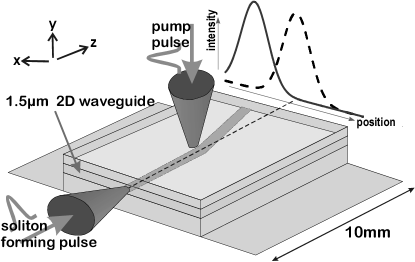
The waveguide structure we employ consists of a m thick, 10 mm long (in the direction) AlxGa1-xAs waveguiding layer (, band gap = 1.64 eV nm) sandwiched in a m thick lower and a m upper cladding both with . The pulses used to generate and steer the solitons are obtained from an ultrafast laser system: a 250 kHz optical parametric amplifier producing 190 fs pulses, centered at nm (photon energy = 0.8 eV). For soliton formation a 1.4 kW peak power pulse is elliptically shaped by a cylindrical telescope (to enable good coupling into the waveguide) and subsequently passed through a 11 mm focal length lens to obtain an appropriate lateral width at the waveguide. The in-plane intensity diameter is m (measured at points) at the entrance facet with the light polarized in-plane. We observe that the soliton maintains its width for the linear diffraction length having a width of m at the exit facet. The pump or steering pulse has a peak power of 220 kW and is focused to a diameter (at points) of m polarized parallel to the soliton polarization. The peak intensity is a factor of five below the damage threshold. For maximal deflection the center of the pump pulse focus is located 0.5 mm from the entrance facet and displaced laterally from the soliton channel so that the soliton experiences the largest lateral variation in the induced refractive index (see below). The time delay, , between the soliton and the pump pulse is controlled with a delay stage.
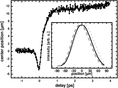
Fig. 2 shows the change in the center of the soliton lateral intensity distribution at the exit facet, as a function of . The fast, pulse width limited deflection towards the pump beam position near is attributed to the third-order nonlinear optical response, the optical Kerr effect, and peaks at m. For an estimated peak focused intensity GW cm-2 and a Kerr coefficient ofAitchisonJQA1997 cm2GW-1 we estimate a peak refractive index change of . However, for larger than the temporal pulse width the deflection reverses, bends away from the pump location and achieves a maximum value m, due to the refractive index change induced by free carriers. For even higher intensities, obtained by tighter focusing of the pump beam, and yielding higher carrier densities, deflections up to m have been achieved, corresponding to a deflection angle of 8 mR; this is larger than the soliton diameter by more than a factor of two. The Drude-based change to the refractive index via free carriers of density, , is most likely due to three-photon absorption; two-photon absorption is not energetically allowed. Indeed, from Wherret’s scaling lawsAitchisonJQA1997 ; WherrettJOSAB84 for multiphoton absorption we estimate a 3-photon absorption coefficient of 0.05 cm3GW-2, so that the injected carrier density is estimated to be . From the refractive index change with carrier densityUlmerOL1999 for 1550 nm, we obtain a peak refractive index change of .
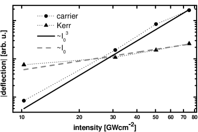
Fig. 3 shows how the Kerr-induced and carrier-induced deflection amplitudes scale with the focussed pump intensity . As expected the former scales linearly with , consistent with a Kerr effect, while the latter scales as in accord with three photon absorption or a cascaded three-photon absorption processes. The carrier-induced response rises on a time scale related to the pulse width, although it might be noted that there is a “slow” (1 ps rise time) component. This is attributed to cooling of the carriers, perhaps also involving intervalley scattering, with the effective mass of conduction band electrons decreasing and enhancing the Drude contribution to the refractive index change. The carrier-induced response remains for the carrier lifetime which is of the order of several hundreds picoseconds for our sample. With appropriate engineering the recombination time could be reduced or carrier induced changes could be enhanced. Alternatively carrier responses can be avoided, by working with lower peak intensity by e.g., using a larger focal area. The maximum deflection is then limited by the pump pulse energy and the temporal pulse width. Note that with the present experiments, the onset of the carrier-induced refractive index change partly masks the Kerr effect and the actual Kerr induced deflection in Fig. 2 is likely to be much larger than the m indicated.
A simple estimate of the observed deflection for refractive index changes due to the optical Kerr effect can be given as follows. Consider a planar slab waveguide contained along the y direction with light propagating in the z direction as indicated in Fig. 1 The nonlinear wave equation is
| (1) |
with where is the refractive index of the slab and . The solution to (1) is:
| (2) |
where is the amplitude of the so-called bright soliton and is its width. A Kerr-induced change in the refractive index along the x-direction, with the ultrafast pump and soliton pulses overlapping in time, in addition to the one already induced by the soliton itself, leads to a spatially dependent phase-shift for the propagating soliton and therefore a refraction towards the direction of the gradient of the phase-shift. The index variation induced by a pulse focused onto the waveguide is taken to be of the form where is the peak intensity of the focused pump beam, is its width and is the center of the focal spot. If the focused beam is located so that at the center of the soliton (i.e. for ) and if we assume , to a first approximation a linear phase differential, is induced in the soliton between with:
| (3) |
In general, a soliton travelling through the waveguide at a small angle with respect to the z-direction can be described byHasegawaSPRINGER :
| (4) |
which is equivalent to the solution in Eq. 2 at the place of deflection () multiplied by a phase factor . The phase differential can be related to the generic phase shift at through
| (5) | |||||
| (6) |
This gives a deflection angle of
| (7) |
With and GWcm-2 Eq. 7 gives mR. This is within a factor of 3 the observed Kerr induced deflection angle of mR, although the Drude effect partially obscures the Kerr effect. The deflection angles reported here are comparable to those achieve with switching techniques involving co-propagating solitons and electrically induced prisms although the interaction lengths are much longerkangOL96 ; friedrichOL98 .
In summary we have demonstrated the feasibility of all-optical alteration of the pathways of spatial solitons in two dimensional semiconductor waveguides on an ultrafast time scale, employing the optical Kerr nonlinearity of the medium. The deflection scheme reported here does not require a precise geometrical form for the refractive index change. It also offers complementary degrees of freedom to the co-propagating soliton switching scheme. In addition we have observed Drude-induced deflection of spatial solitons. The ultrafast temporal nature and particular geometry of the deflection technique enables one to write and perform information processing applications using spatial solitons, with the maximum deflection angle limited only by the maximum possible phase shift across the soliton. By merging the capabilities of the approach described here with the scheme of optical interconnects friedrichOL98 additional applications are possible.
We acknowledge the support of the Sciences and Engineering Research Council, Canada and Photonics Research Ontario.
References
- (1) S. Trillo and W. Toruellas, eds., Spatial Solitons, vol. 82 of Springer Series in Optical Sciences (Springer, 2001).
- (2) S. Blair and K. Wagner, Appl. Opt. 38(32), 6749 (1999).
- (3) T.-T. Shi and S. Chi, Opt. Lett. 15(20), 1123 (1990).
- (4) J. U. Kang, G. I. Stegeman, and J. S. Aitchison, Opt. Lett. 21(3), 189 (1996).
- (5) W. Haas, R. Johannes, and P. Cholet, Appl. Opt. 3(8), 988 (1964).
- (6) S. Shwartz, M. Segev and U. El-Hannay, Opt. Lett. 29(7), 760 (2004).
- (7) Y. Li, D. Y. Chen, L. Yang, and R. R. Alfano, Opt. Lett. 16(6), 438 (1991).
- (8) G. Roosen and G. T. Sincerbox, J. Appl. Phys. 54(3), 1628 (1983).
- (9) P. V. Mamyshev, A. Villeneuve, G. I. Stegeman, and J. S. Aitchison, Electron. Lett. 30(9), 726 (1994).
- (10) J. S. Aitchison, D. C. Hutchings, J. U. Kang, G. I. Stegeman, and A. Villeneuve, IEEE JOURNAL OF QUANTUM ELECTRONICS 33(3), 341 (1997).
- (11) B. S. Wherrett, J. Opt. Soc. Amer. B 1, 67 (1984).
- (12) T. G. Ulmer, R. K. Tan, Z. Zhou, S. E. Ralph, R. P. Kenan, C. M. Verber, and J. SpringThorpe, Opt. Lett. 24(11), 756 (1999).
- (13) A. Hasegawa and M. Matsumoto, Optical Solitons in Fibers (Springer, 2003).
- (14) L. Friedrich, G. I. Stegeman, P. Millar, C. J. Hamilton, and J. S. Aitchison, Opt. Lett. 23(18), 1438 (1998).