Limitations of Nanotechnology for Atom Interferometry
Abstract
Do van der Waals interactions determine the smallest nanostructures that can be used for atom optics? This question is studied with regard to the problem of designing an atom interferometer with optimum sensitivity to de Broglie wave phase shifts. The optimum sensitivity to acceleration and rotation rates is also considered. For these applications we predict that nanostructures with a period smaller than 40 nm will cause atom interferometers to perform poorly because van der Waals interactions adversely affect how nanostructure gratings work as beam-splitters.
pacs:
03.75.Dg, 81.16.Ta, 34.50.DyAtom interferometers that are built with nanostructure gratings have proven their ability to detect small perturbations to atomic de Broglie waves. Examples of quantities measured with this technique include: the polarizability of Na atoms Ekstrom et al. (1995), the index of refraction for Na atom waves due to a dilute gas Schmiedmayer et al. (1995); Roberts et al. (2002), the strength of atom-surface van der Waals interaction potentials Perreault and Cronin (2005), and the rotation rate of a platform Hammond et al. (1997); Lenef et al. (1997). Because all of these measurements are related to interference fringe phase shifts, an important design goal for atom interferometers is to optimize the sensitivity to the phase of an interference pattern. This goal was discussed by Scully and Dowling (1993) for matter-wave interferometers in general, and then discussed for atom interferometers that are based on mechanical absorption gratings by Pritchard Berman (1997); Lenef et al. (1997) and also by Vigué Champenois et al. (1999); Delhuille et al. (2002). However, none of these analyses specifically include the effect of van der Waals (vdW) interactions between atoms and the nanostrucure gratings. In this paper we review how phase sensitivity can be maximized by selecting the open fraction of each grating; then we show how vdW interactions modify these calculations. Finally, we show how vdW interactions determine the minimum period of nanostructure gratings that can optimize the performance of atom interferometers for inertial sensing.
van der Waals interactions between atoms and material gratings change the diffraction efficiencies, , which we define as the modulus of the diffracted wave amplitude in the th order as compared the wave amplitude incident on the grating,
| (1) |
The effect of vdW interactions is generally marked by an increase in for and a decrease in , but the efficiencies depend non-linearly on the strength of vdW interactions as discussed in Grisenti et al. (1999); Bruhl et al. (2002); Grisenti et al. (2000); Perreault et al. (2005); Cronin and Perreault (2004). In this paper we will use newly identified scaling laws for to describe how the vdW interactions affect the interference pattern and the statistical sensitivity to phase shifts in a three-grating Mach-Zehnder atom interferometer. The impact of vdW interactions is particularly important if the grating period is reduced below 100-nm and the atom beam velocity is reduced below 1000 m/s. This analysis shows how vdW forces set fundamental limits on the smallest nanostructure features that can be used for atom interferometry. For example, grating windows that are 20 nm wide will optimize the sensitivity to rotations or accelerations for an atom interferometer with 1000 m/s Na atoms and 150 nm thick silicon nitride gratings.
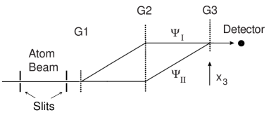
The layout of a Mach Zehnder atom beam interferometer is shown in figure 1. The first grating (G1) serves as a beam splitter. The second grating (G2) redirects the beams so they overlap in space and make a probability density interference pattern just before the third grating (G3). Because the detector in this example is located close enough to G3 so that diffraction from G3 is not resolved, the third grating simply works as a mask. The transmitted flux depends on position of the third grating, , relative to the other gratings as
| (2) |
where is the average transmitted atom beam intensity, is the contrast defined as
| (3) |
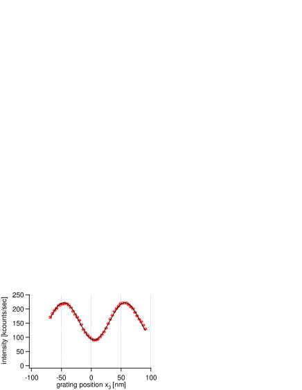
is the wavenumber of the grating, and is the phase that the interferometer is designed to measure. An example of interference fringe data and a best-fit function for based on equation 2 is shown in figure 2. The values of , , and are free parameters in the fit, but the period nm in figure 2 is determined by the gratings, and the distance is independently measured with a laser interferometer as described in Keith et al. (1991).
As discussed in Scully and Dowling (1993); Lenef et al. (1997); Berman (1997), the measured fringe phase, , is predicted to have a statistical variance, , due to shot noise (counting statistics) given by
| (4) |
where is the total number of atoms counted. To minimize the uncertainty in phase we therefore seek to maximize the quantity which is proportional to . This can be achieved by increasing the observation time, increasing the intensity of the atom beam incident on the interferometer (), increasing the quantum efficiency of the detector, and, depending on the beam collimation, by increasing the detector size. Maximizing can also be achieved by choosing specific open fractions for the three gratings because the open fractions affect and relative to . The open fractions are defined as where is the window size for the th grating (G1 G2 or G3), and is the grating period. We will show that other factors in addition to the open fractions such as the strength of the vdW interaction, the atom beam velocity, and the absolute size of the nanostructure gratings are needed to completely determine and relative to .
The interference pattern just before G3 is
| (5) | |||||
| (6) | |||||
| (7) |
where and are the wave functions of the two beams incident on G3, and the notations and denote the diffraction efficiency for G1 or G2 into the th order. Equation 7 looks similar to equation 2 but the primes indicate the position, intensity, and contrast of the interference pattern just before G3.
The intensity transmitted through the third grating, , is related to the intensity by
| (8) |
Equation 8 describes the result of Moiré filtering of the interference pattern by G3, with the grating acting as a binary valued (Ronchi-rule) mask. The result of combining equations 7 and 8 to get
| (9) |
lets us identify and in terms of and respectively as
| (10) | |||||
| (11) |
Furthermore, the values and are related to the diffraction efficiencies by equations 6 and 7, so that after the third grating and can be expressed as
| (12) | |||||
| (13) |
The quantity we seek to maximize, , can now be written in terms of the diffraction efficiencies for G1 and G2 and the open fraction for G3:
| (14) |
The figure of merit, , in equation 14 has been factored into three bracketed terms that are each determined by only one grating G1 G2 or G3. Each term in brackets can then be maximized independently. To obtain equation 14, it was assumed that , which is verified to be a good approximation by the symmetry of the experimentally observed diffraction patterns Chapman and et al. (1995); Grisenti et al. (2000).
Note that if diffraction from G3 can be resolved, as in the interferometer built by Toennies Toennies (2001, 2005), then G3 acts as a beam combiner (not a mask) and becomes a function of the diffraction efficiencies of all three gratings. This applies also for phase gratings and has been considered by Vigué Champenois et al. (1999), however we will restrict this paper on vdW interactions to the case of nanostructure gratings with G3 acting as a mask. Near field diffraction from the collimating slits and dependent near field effects from G3 are explicitly ignored here.
To state the figure of merit in equation 14 in terms of the physical dimensions of each grating the next step is to evaluate the diffraction efficiencies. If vdW interactions with the grating bars are ignored then the diffraction efficiency for atom wave amplitude into the th transmission diffraction order is given by
| (15) |
where is the grating window size and is the grating period. Equation 15 is valid in the far-field (Fraunhofer) approximation and gives the familiar sinc envelope function for diffraction intensities .
Using equation 15 for the diffraction efficiencies we can write in terms of the open fractions of the three gratings:
| (16) |
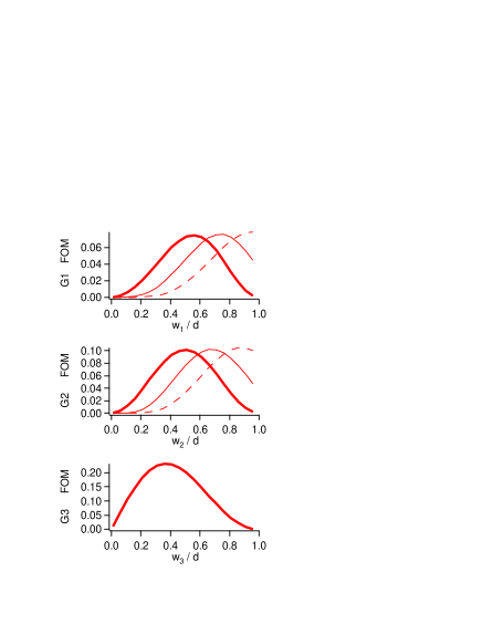
The three bracketed terms in equation 16 are functions of , , and respectively, and each term can be maximized independently as shown in Figure 3. The open fractions for (G1, G3, G3) that maximize are (0.56, 0.50, 0.37). The maximum value of is obtained when the contrast is and the average intensity is . It is noteworthy that a low value of is hard to avoid because the gratings are, after all, absorption gratings. These values for , , , , and that maximize reproduce the results stated in Berman (1997) and are listed on the first row of table 1. This concludes our review of how to get optimum interference fringe patterns (with minimum ) from an atom interferometer built with three nanostructure gratings assuming vdW interactions are negligible.
Next we will show how vdW interactions modify the best open fractions for G1 and G2. To predict how the diffraction efficiencies change as a result of the vdW interaction we will use a numerical calculation described in Perreault et al. (2005); Cronin and Perreault (2004) and summarized here. The van der Waals potential is
| (17) |
where is the distance to an infinite plane and is the vdW coefficient. The vdW coefficient for sodium atoms and silicon nitride surfaces has been measured to be meVnm3 Perreault et al. (2005) and for helium and silicon nitride meVnm3 Grisenti et al. (1999). The phase shift for atom waves passing through a slot between two grating bars, as discussed in references Perreault and Cronin (2005); Cronin and Perreault (2004); Perreault et al. (2005); Grisenti et al. (1999, 2000); Bruhl et al. (2002), is
| (18) |
where is the coordinate inside the grating channel ( in the middle of the window), is the thickness of the grating, is Planck’s constant divided by 2, and is the atom beam velocity. Equation 18 is obtained by assuming parallel-sided slot walls, neglecting edge effects at the entrance and exit to the slot, and using the WKB approximation to first order in (potential over kinetic energy). Despite all these approximations, equation 18 has been used (occasionally with a modification for non-parallel walls) to explain several experimental observations regarding vdW interactions between atoms and nanostructure gratings Perreault et al. (2005); Cronin and Perreault (2004); Perreault and Cronin (2005); Grisenti et al. (1999); Bruhl et al. (2002).
With the vdW-induced phase shift, , given by equation 18 incorporated into the transmission function for the grating, the diffraction efficiencies in the far-field approximation are
| (19) |
By combining equations 18 and 19 and performing the change of variables we can re-write the efficiencies in terms of three linearly independent dimensionless parameters so that is explicitly
| (20) |
where the independent parameters are
| (21) | |||||
| (22) | |||||
| (23) |
This exact choice of parameters is arbitrary, but convenient to simplify equation 20. The diffraction efficiencies thus depend on the vdW coefficient, atom velocity, grating period, grating thickness, and the grating open fraction. This can be compared to equation 15 in which the efficiencies depend only on the open fraction. If , the efficiencies depend only on and , and equation 20 reduces to equation 15.
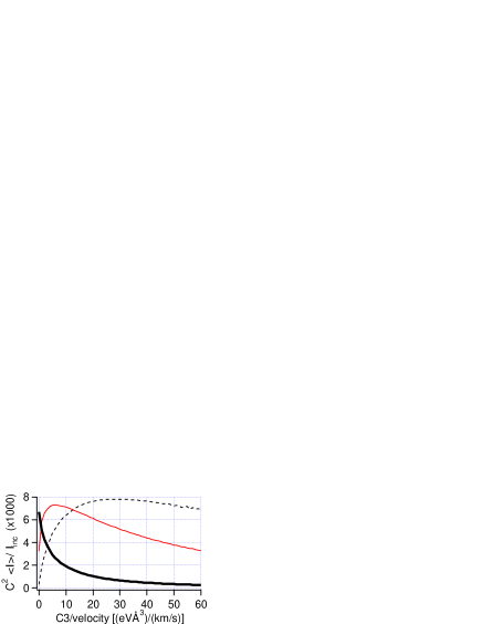
Now we have derived all the relationships (equations 14 and 20) needed to compute the figure of merit as a function of the vdW coefficient . Figure 4 shows the quantity as a function of for parameters (=1000 m/s, =100 nm, = 150 nm and open fractions ) that are similar to those in experiments Ekstrom et al. (1995); Schmiedmayer et al. (1995); Roberts et al. (2002); Perreault and Cronin (2005); Hammond et al. (1997); Lenef et al. (1997); Toennies (2005) with supersonic atom beams and state-of-the-art silicon nitride nanostructure gratings. As shown in figure 4, the figure of merit for this set of parameters is a monotonically decreasing function of . In other words, the sensitivity to phase shifts becomes worse as vdW interactions get stronger. For gratings with geometric dimensions that are related by the ratios () similar to the 100-nm period gratings that are now available, the quantity is reduced by more than 1/2 (which means that a measurement of with comparable uncertainty would require more than twice as much time) when
| (24) |
Since this condition is nearly satisfied in experiments Ekstrom et al. (1995); Schmiedmayer et al. (1995); Roberts et al. (2002); Perreault and Cronin (2005); Hammond et al. (1997); Lenef et al. (1997); Toennies (2005), we are motivated to ask the question, “is it ever worth using sub-100-nm period gratings for atom interferometry?” Or, to paraphrase Richard Feynmann, “is there no more room at the bottom?” We will address this question by exploring how the open fractions and all the parameters in affect the figure of merit for minimum ; then as a separate issue we will investigate how the sensitivity to rotation and acceleration is affected by vdW interactions.
The open fractions can be made larger or smaller by altering the nanostructure fabrication procedure described in Schattenburg et al. (1990); Savas et al. (1995, 1996). So we used equations 14 and 20 to specify what open fractions should be chosen to optimize the interferometer if = 3 meV nm3 and the other parameters are kept m/s, nm, and nm. The three terms that contribute to the result for in equation 14 are each plotted in figure 3 as a function of open fraction for the cases = 0, 3, and 30 meVnm3. The optimum open fractions for each of these cases are summarized in table 1, and were used to generate additional functions plotted in figure 4 for vs .
The new values of and that maximize when are significantly larger than the optimum values found for the case of . This can be understood qualitatively because larger open fractions are needed to compensate for the effect of increased ; increasing the strength of the vdW interaction causes a change to that is similar to (but not exactly the same as) the effect of decreasing the open fraction of the grating.
If extremely large open fractions () are possible to obtain for G1 and G2, then it is approximately correct to replace the equation 24 by stating that is reduced below 1/2 of its optimum value when
| (25) |
This last condition is consistent with replacing in equation 24, and is verified by simulations. For grating-atom combinations that do not satisfy the inequality 25, it is not possible to restore to the optimum value of 0.0070 regardless of the open fractions. This shows that vdW interactions set a fundamental limit on the smallest nanostructures that can be used for atom interferometry before the performance as determined by the minimum degrades.
Equation 25 can be approximately derived analytically by finding the condition for which the phase begins to oscillate rapidly () when . This analytic approach is justified because the regions of rapidly oscillating phase do not contribute significantly to the integral in equation 19, and we know from our earlier study of optimization without vdW interactions that the combination of replacing the limits by approximately and and ignoring the term in equation 19 yields the optimum for G1 and G2. The analytic approach described here gives the condition
| (26) |
which is consistent with equation 25 within a factor of for the case .
| 0 | 0.56 | 0.50 | 0.37 | 0.67 | 0.015 | 0.0070 |
| 3 | 0.56 | 0.50 | 0.37 | 0.76 | 0.007 | 0.0040 |
| 30 | 0.56 | 0.50 | 0.37 | 0.79 | 0.001 | 0.0008 |
| 3 | 0.75 | 0.67 | 0.37 | 0.66 | 0.016 | 0.0072 |
| 30 | 0.93 | 0.88 | 0.37 | 0.68 | 0.016 | 0.0075 |
optimized open fractions for the specific .
Identifying the independent parameter helps to clarify several scaling laws. For example, if every geometric dimension of the gratings (,, and ) were multiplied by , then the efficiencies would change as if because appears in . For example, if -scale gratings could be obtained then the results in figures 3 and 4 for meVnm3 would apply.
The vdW coefficient for He atoms is the smallest of any atom, so the impact of vdW interactions should be minimal for He atoms. In another example of a scaling law, the efficiencies , and figure of merit that we have discussed for Na atoms (with ) will apply for the case of He atoms (with ) if geometrically similar gratings with new period of are used. Thus, for a He atom beam with m/s, nanostructure gratings with a minimum dimension of nm could be used before is doubled from vdW interactions.
Next we address the question, “What period grating would optimize an atom beam gyrometer or accelerometer?” Because the interference fringe phase shift, , due to either rotation or acceleration depends on and there is a different function to optimize for optimum sensitivity to inertial displacements.
The Sagnac phase shift for a matter wave interferometer rotating at the rate is
| (27) | |||||
| (28) |
where is the area enclosed by the interferometer paths, and is the distance between gratings G1 and G2 (or equivalently G2 and G3) Lenef et al. (1997). In the last equation it was assumed that the vector orientations of and are parallel. The statistical variance in measured rotation rate will then be given by
| (29) | |||||
| (30) |
Hence, maximizing the quantity
| (31) |
will minimize the variance in measured rotation rate, and will therefore minimize the angle random walk obtained when using a gyrometer for inertial navigation. For measurements of acceleration with minimum variance, the quantity should be maximized.
The tradeoff is as follows. For smaller an atom interferometer gyroscope is limited by vdW interactions, and for larger the response factor () is smaller. The quantity is plotted in figure 5 as a function of assuming m/s, meVnm3 and () for each grating. An optimum period of 44 nm is found.
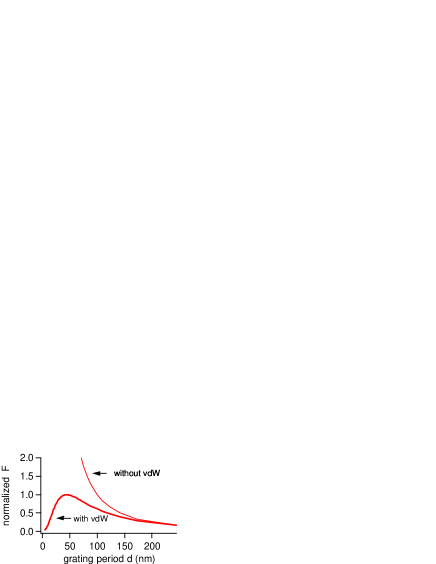
The main result is that nanostructure gratings with a period smaller than nm will not improve atom beam interferometer gyroscopes or accelerometers unless the vdW limitation is overcome. This limitation can be circumvented somewhat if large open fractions are used, or by choosing atom-surface combinations that have a small vdW coefficient , or by reducing the grating thickness independently of as shown in equation 24 or by adjusting atom velocity to maximize the figure of merit shown in equation 31. Some of these advantages could be realized if gratings were fabricated from an array of carbon nanotubes.
In conclusion, we have shown how atom interferometers are affected by vdW interactions between atoms and nanostructure gratings. We have shown how to calculate the contrast and intensity of the interference pattern given the parameters: grating thickness (), grating period (), grating open fractions (, atom velocity (), and vdW coefficient (). We described how to select open fractions that will optimize an interferometer for maximum sensitivity to interference fringe phase shifts. For experiments with the currently available parameters ( = 150 nm, = 100 nm, = 1000 m/s, = 3 meVnm3), we report the open fractions that minimize the uncertainty in phase () are given by . If the gratings are made with a period smaller than nm, then regardless of the open fractions, the statistical sensitivity to phase shifts (given by the uncertainty ) will grow because of the way vdW interactions adversely affect how the gratings operate as beam splitters. For maximum sensitivity to rotation or acceleration, there is a minimum grating period in the range of 40 nm. Thus van der Waals interactions place a limitation on the smallest nanostructure gratings that can be used for atom interferometry.
This work was supported by an award from Research Corporation and the National Science Foundation Grant No PHY-0354947.
References
- Ekstrom et al. (1995) C. Ekstrom, J. Schmiedmayer, M. Chapman, T. Hammond, and D. E. Pritchard, Phys. Rev. A 51, 3883 (1995).
- Schmiedmayer et al. (1995) J. Schmiedmayer, M. Chapman, C. Ekstrom, T. Hammond, S. Wehinger, and D. Pritchard, Phys. Rev. Lett. 74, 1043 (1995).
- Roberts et al. (2002) T. D. Roberts, A. D. Cronin, D. A. Kokorowski, and D. E. Pritchard, Physical Review Letters 89 (2002).
- Perreault and Cronin (2005) J. D. Perreault and A. D. Cronin, arXiv:physics/0505160 (2005).
- Hammond et al. (1997) T. Hammond, M. Chapman, A. Lenef, J. Schmiedmayer, E. Smith, R. Rubenstein, D. Kokorowski, and D. Pritchard, Braz. J. Phys. 27, 193 (1997).
- Lenef et al. (1997) A. Lenef, T. Hammond, E. Smith, M. Chapman, R. Rubenstein, and D. Pritchard, Phys. Rev Lett. 78 (1997).
- Scully and Dowling (1993) M. Scully and J. Dowling, Phys. Rev. A 48, 3186 (1993).
- Berman (1997) P. R. Berman, ed., Atom Interferometry (Academic Press, 1997).
- Champenois et al. (1999) C. Champenois, M. Buchner, and J. Vigue, European Physical Journal D 5, 363 (1999).
- Delhuille et al. (2002) R. Delhuille, A. Miffre, B. V. de Lesegno, M. Buchner, C. Rizzo, G. Trenec, and J. Vigue, Acta Physica Polonica B 33, 2157 (2002).
- Grisenti et al. (1999) R. E. Grisenti, W. Schollkopf, J. P. Toennies, G. C. Hegerfeldt, and T. Kohler, Phys. Rev. Lett. 83, 1755 (1999).
- Bruhl et al. (2002) R. Bruhl, P. Fouquet, R. E. Grisenti, J. P. Toennies, G. C. Hegerfeldt, T. Kohler, M. Stoll, and D. Walter, Europhys. Lett. 59, 357 (2002).
- Grisenti et al. (2000) R. E. Grisenti, W. Schollkopf, J. P. Toennies, J. R. Manson, T. A. Savas, and H. I. Smith, Phys. Rev. A 61, 033608 (2000).
- Perreault et al. (2005) J. D. Perreault, A. D. Cronin, and T. A. Savas, Phys. Rev. A 71, 053612 (2005).
- Cronin and Perreault (2004) A. D. Cronin and J. D. Perreault, Phys. Rev. A 70, 043607 (2004).
- Keith et al. (1991) D. W. Keith, C. R. Ekstrom, Q. A. Turchette, and D. Pritchard, Phys. Rev. Lett. 66, 2693 (1991).
- Chapman and et al. (1995) M. S. Chapman and et al., Phys. Rev. Lett. 74, 4783 (1995).
- Toennies (2001) J. P. Toennies, Hinshelwood Lecutures, Oxford (2001).
- Toennies (2005) J. P. Toennies, personal commuinication (2005).
- Schattenburg et al. (1990) M. l. Schattenburg, E. H. Anderson, and H. I. Smith, Phys. Scripta 41, 13 (1990).
- Savas et al. (1995) T. A. Savas, S. N. Shah, M. L. Schattenburg, J. M. Carter, and H. I. Smith, Journal of Vacuum Science and Technology B 13, 2732 (1995).
- Savas et al. (1996) T. A. Savas, M. L. Schattenburg, J. M. Carter, and H. I. Smith, J. Vac. Sci. Tech. B 14, 4167 (1996).