Research School of Physical Sciences and Engineering,
Australian National University, Canberra, ACT 0200, Australia
(Fax: +61-26125-8277, Email:skm124@rsphysse.anu.edu.au)
Beaming effect from increased-index photonic crystal waveguides
Abstract
We study the beaming effect of light for the case of
increased-index photonic crystal (PhC) waveguides, formed through
the omission of low-dielectric media in the waveguide region. We
employ the finite-difference time-domain numerical method
for characterizing the beaming effect and determining the
mechanisms of loss and the overall efficiency of the directional
emission. We find that, while this type of PhC waveguides is
capable of producing a highly collimated emission as was
demonstrated experimentally, the inherent characteristics of the
structure result in a restrictively low efficiency in the coupling
of light into the collimated beam of light.
PACS42.70.Qs; 78.20.Bh
1 Introduction
Photonic crystals (PhC) are expected to play an important role in the development of small integrated optical circuits, combining the diverse functionality of optical devices and intra-connections that confine light on a sub-wavelength scale. Yet, associated with this sub-wavelength confinement of light is the complexity of interfacing the small light waveguides and cavities of photonic crystals with conventional optical systems such as fibers, waveguides, and freely propagating light beams. Indeed, coupling light directly out of PhC waveguides into free-space in an usable manner is particularly challenging due to the strong diffraction of light by the sub-wavelength dimensions of the waveguide exit Bethe1944 . However, the beaming effect of light, which has been studied in metallic-thin-film systems Ebbesen_N_98 ; Lezec_S_02 and shown to exist in PhCs Moreno_PRB_04 ; Moreno_PNFA_04 ; Kramper_PRL_04 , has been suggested as a possible approach to overcome these limitations, allowing highly directed emissions from PhC waveguides that exist below the diffraction limit. To overcome the diffraction limit and achieve a directed emission, the beaming effect utilizes leaky surface modes and coherent interference to redistribute the power of the transmitted light into a narrow beam directly in front of the waveguide exit. Coupling from the leaky or radiative surface modes is achieved through a periodic corrugation in the exit surface of the PhC structure, with the geometric and material properties of this corrugation establishing a spatial phase and amplitude distribution within the radiated field that, under appropriate conditions, leads to a highly directed emission.
However, the full utility and efficiency of the beaming effect is yet to be determined. Our recent study has illustrated the potential to substantially enhance and control the beaming effect by engineering the surface and near-surface structure of a particular PhC SKM_APL_05 . In this case, the enhanced beaming structure makes use of a PhC created using a square lattice of high dielectric rods in air, where a row of rods is removed to form a waveguide. Unfortunately, this type of PhC does not exhibit a complete photonic band gap (PBG) for both polarisations of light and the surface structure required for the beaming effect is not easy to fabricate. For these reasons, in this paper we examine the effectiveness of the beaming effect in the more readily manufactured PhC structure—a triangular lattice of holes in a high dielectric material—in which the beaming effect has been experimentally demonstrated Kramper_PRL_04 . A waveguide can be formed within this PhC through the omission of a row of holes to create an increased-index guiding region that does exhibit a PBG for both polarisations of light. In this paper, we analyze, by the finite-difference time-domain numerical method, the conditions required to achieve optimal beaming from the increased-index waveguide, highlighting the sources of losses and inefficiencies. From our analysis, we illustrate how this structure, while producing a highly directed emission, does not achieve an efficient coupling to the transmitted light, thus limiting its technological application.
2 Characterisation of the directional emission
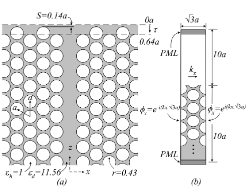
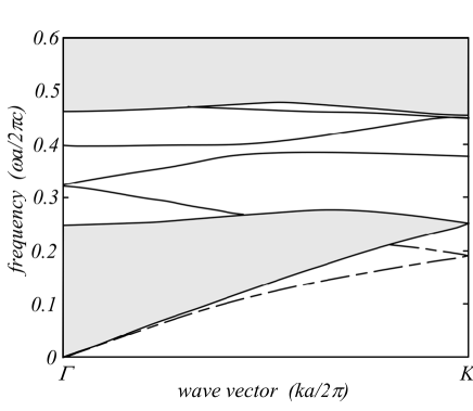
We consider the PhC model based on the experimentally demonstrated structures described, for example, in Refs. Kramper_PRL_04 ; Schilling_JOO_01 . It consists of a two-dimensional triangular lattice of holes created in a background of high dielectric material with a dielectric constant of , representing silicon at a wavelength of . With a hole-radius to lattice-pitch ratio of , a photonic band gap is created for TM polarized light (magnetic field parallel to the hole and travelling in a plane perpendicular to the holes) within the frequency range of to . We orientate the triangular lattice such that the irreducible Brillouin vector is directed along the -axis, and form a waveguide in this direction at , through the omission of a row of holes, as depicted in Fig. 1(a). A Gaussian source is introduced to the waveguide from the waveguide exit to ensure only true waveguide modes are coupled from the guide. The dispersion relationships for the even-symmetry modes of this waveguide are presented in Fig. 2. The terminating surface of the PhC is formed along a plane parallel to the direction, perpendicular to the waveguide. This terminating plane, introduced anywhere within an infinite PhC, leaves partial holes along the surface resulting in a natural surface corrugation, providing wave vector matching to achieve coupling between surface and radiative modes.
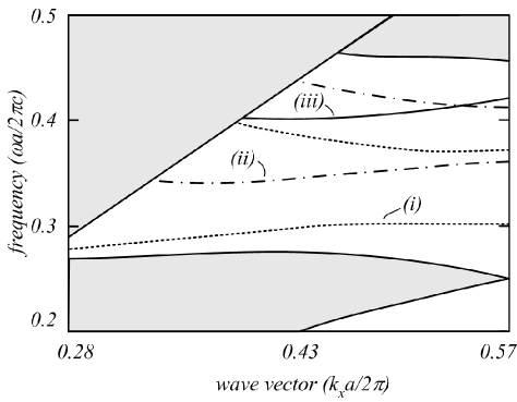
To determine the surface terminations that will support surface modes, a supercell representation of the surface is created with a combination of periodic boundary and perfectly matched layer (PML) boundary conditions, as illustrated in Fig. 1(b). The fields within the supercell are represented as complex numbers, allowing the spatial phase to be varied over the surface Brillouin zone as the eigenmodes of the surface structure are determined from Fourier analysis. A small surface termination region exists that supports surface modes, however, the modes of this region are weakly localized, causing them to be rapidly radiated. This rapid coupling of the surface modes to the radiated field is a result of the sharp cusps of high dielectric created by the partial holes along the surface [see surface of Fig. 1(b)], resulting in an optical rough surface that limits the spatial distribution of the diffractively focussing components of light, thus limiting the formation of the directed emission. To obviate this limited distribution of the surface modes, we apply a dielectric layer to the truncated surface that in-fills the partial holes, as depicted in Fig. 1(a). This in-fill layer has two effects: it reduces the roughness of the surface allowing the surface modes to travel further along the surface, and it changes the surface corrugation period within the range of surface terminations that support surface modes. Again, using the supercell method we calculate the surfaces that support surface modes within the dielectric in-fill region, defined by in Fig. 1(a). Figure 3 illustrates the dispersion relations for three surface terminations () within this region.
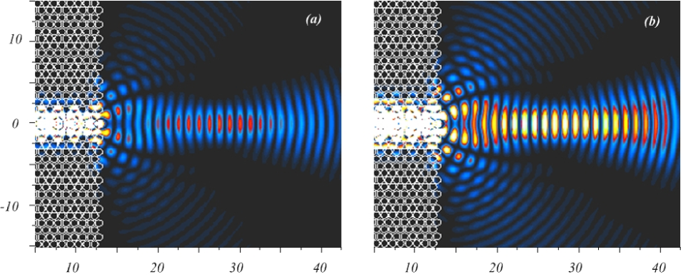
A spectral analysis of a series of terminations within the surface mode forming region reveals that optimal beaming occurs for a surface termination of at frequencies corresponding to the band-edges of the waveguide’s mini-stop band Agio_PRE_01 [see Fig.2], where the waveguide mode’s group velocity tends to zero, increasing the coupling time to surface modes and consequently increasing the power within the diffractively focussing components of light.To characterize this optimal directed transmission we calculate the fraction of power, normalized to the total power, within the central lobe of the directed emission in the simulation domain and between the first nulls of the beam, , and the width of the beam between the first null, , at a distance of in front of the waveguide exit. A likewise normalized measurement is also taken of the combined power within the surface modes and transmitted side lobes, . In addition to these measurements, we calculate the return loss, , expressed at a fraction of the total power, experienced at the waveguide exit. In this manner, we characterize the directed emission for a surface termination of and source frequency to have a directed power of , a return loss of , with the remaining power of , delivered into the surface modes and side lobes. In this configuration, the directed emission has a beam width of , as illustrated in the color contour plot of the spatial light intensity of Fig. 4(a), where the color scaling highlights the beaming. Notably, 77% of the transmitted light emitted from the waveguide is delivered into the highly collimated emission; unfortunately though, this accounts for only 5.4% of the total light. The very poor transmission of light from the waveguide is a result of large Fresnel reflections occurring at the waveguide-vacuum interface as the light attempts to move from a high refractive index to a low refractive-index media. The transmission is also further limited by an impedance mismatch between the waveguide mode and the surface and radiated fields.
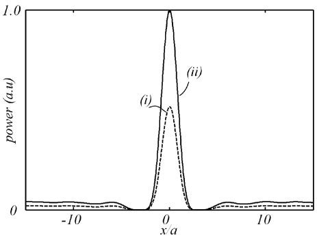
Noting that optimal beaming occurred for a waveguide mode with vanishing group velocity, and that the waveguide exit forms a partially transmitting mirror, we take the findings to their natural extension: a Fabry-Perot resonant cavity. To complete the basic elements of the cavity, we terminate the internal end of the waveguide with the bulk of the photonic crystal, and tune the cavity length to a Fabry-Perot resonance. Using the previously described characterization method, we find the direct emission is doubled, the power within the surface modes and side lobes equally doubled, and the beam width maintained. The reflection coefficient at the waveguide exit is expected to be similar to that of the initial structure, as there is minimal change to the waveguide mode structure. The spatial distribution of the field intensity for the Fabry-Perot cavity beaming is illustrated in Fig. 4(b), with a plot of the power cross-section highlighting the beaming profile of the two structures given in Fig. 5.
3 Discussions
We believe that the primary difficulty in achieving highly efficient coupling of light into the directional emission is the large Fresnel reflections that occur from the step change in the refractive index at the waveguide-vacuum interface. As this step change is fundamental to the waveguide structure, little can be done to reduce this source of inefficiency. Minor reduction of the reflections may be possible for different mode symmetries at different bands of the dispersion relationship or with the introduction of defects within the waveguide and near the exit, as has been demonstrated in the experimental setup Kramper_PRL_04 . However, in introducing these changes the other conditions from optimal beaming—low group velocity and source frequency matching to the surface corrugation period—would change, requiring further engineering of the structure. Indeed, the large reflections at the waveguide exit are not the only issue of a possible concern. The narrow bandwidth for optimal beaming is also a restrictive attribute; limiting the information-carrying capacity of light transmitted from the waveguide. Indeed, in its present form, the low bandwidth capacity of the beaming effect would prevent it from being used in control or communication applications, with this restriction being general to the beaming effect’s mechanism of operations, and not just the PhC and waveguide structure considered here.
However, as demonstrated by the Fabry-Perot cavity beaming, the beaming effect can be used to collimate light from cavity defects, opening the possibility for controlling and shaping the emissions from near-surface light sources such as light emitting diodes and lasers. Indeed, the mechanism for determining optimal beaming—low group velocity within the cavity to improve the coupling time to surface modes—reinforces this application.
4 Conclusions
We have analyzed the conditions for optimal beaming of light from an increased-index waveguide formed within a PhC structure created by a triangular lattice of holes in a high dielectric material. From this analysis, we have demonstrated the inefficiencies that result from large Fresnel reflections that occur at the waveguide-vacuum interface, and how this loss mechanism will be fundamental to all such high-index waveguide structures used to produce the beaming effect, thus limiting the technological applications of this type of PhC structure.
Acknowledgements
We acknowledge the support of the Australian Research Council through the Centre of Excellence Program and useful discussions with Sergei Mingaleev and Costas Soukoulis.
References
- [1] H. A. Beth. Phys. Rev., 66, 1944.
- [2] T. W. Ebbesen, H. J. Lezec, H. F. Ghaemi, T. Thio, and P. A. Wolff. Nature, 391, 1998.
- [3] H. J. Lezec, A. Degrion, E. Devaux, R. A. Linke, L. Martín-Moreno, F. J. Garcia-Vídal, and T. W. Ebbesen. Science, 297, 2002.
- [4] E. Moreno, F. J. Garcia-Vídal, and L. Martín-Moreno. Phys. Rev. B, 69, 2004.
- [5] E. Moreno, F. J. Garcia-Vídal, and L. Martín-Moreno. Photon. Nano. Fund. Appl., 2, 2004.
- [6] P. Kramper, M. Agio, C. M. Soukoulis, A. Birner, F. Müller, R. B. Wehrspohn, U. Gösele, and V. Sandoghdar. Phys. Rev. Lett., 92(11), 2004.
- [7] S. K. Morrison and Y. S. Kivshar. Appl. Phys. Lett., 86(1), 2005.
- [8] J. Schilling, R. B. Wehrspohn, A. Birner, F. Müller, R. Hillebrand, U. Gösele S. W. Leonard, J. P. Mondia, F. Genereux, H. M. van Driel, P. Kramper, V. Sandoghdar, and K. Busch. J. Opt.A: Pure Appl. Opt, 3, 2001.
- [9] M. Agio and C. M. Soukoulis. Phys. Rev. E, 64, 2001.