Influence of optical aberrations in an atomic gyroscope
Abstract
In atom interferometry based on light-induced diffraction, the optical aberrations of the laser beam splitters are a dominant source of noise and systematic effect. In an atomic gyroscope, this effect is dramatically reduced by the use of two atomic sources. But it remains critical while coupled to fluctuations of atomic trajectories, and appears as a main source of noise to the long term stability. Therefore we measure these contributions in our setup, using cold Cesium atoms and stimulated Raman transitions.
pacs:
PACS-03.75.DgAtom and neutron interferometry and PACS-42.15.FrAberrations and PACS-32.80.PjOptical cooling of atoms; trapping1 Introduction
Since the pioneering demonstrations of interferometry with de Broglie atomic waves using resonant light BordePTB ; Bragg and nanofabricated structures Prit91 as atomic beam splitters, a number of new applications have been explored, including measurements of atomic and molecular properties, fundamental tests of quantum mechanics, and studies of various inertial effects Berman . Using atom interferometers as inertial sensors is also of interest for geophysics, tests of general relativity Hyper , and inertial guidance systems.
Atom interferometers based on light-induced beam splitters have already demonstrated considerable sensitivity to inertial forces. Sequences of optical pulses generate the atom optical elements (e.g., mirrors and beam splitters) for the coherent manipulation of the atomic wave packets Borde91 . The sensitivity and accuracy of light-pulse atom interferometer gyroscopes Gustavson00 , gravimeters Peters99 and gravity gradiometers Snadden98 compare favorably with the performances of state-of-the-art instruments. Furthermore, this type of interferometer is likely to lead to a more precise direct determination of the fundamental constant from the measurement of wicht2001 . In the case of rotation measurements, the sensitivity reaches that of the best laboratory ring laser gyroscope Stedman . Indeed the Sagnac phase shift, proportional to the total energy of the interfering particle, is much larger for atoms than for photons. This compensates for the smaller interferometer area and the lower flux.
In this paper we focus on the effect of the fluctuations of the atomic trajectory, which might affect the long term stability of atomic gyroscopes when coupled with local phase variations induced by optical aberrations. We will introduce this problem in paragraph 2 and illustrate it quantitatively in the case of our setup in paragraph 3.
Our experiment consists in an almost complete inertial measurement unit Yver03 , using cold Cesium atoms that enable for a drastic reduction of the apparatus dimensions while reaching a sensitivity of nrad.sHz-1/2 to rotation and 4x10⁻⁸ m.sHz-1/2 to acceleration. Its operation is based on recently developed atom interference and laser manipulation techniques. Two interferometers with counter-propagating atomic beams discriminate between rotation and acceleration Gustavson98 . Thanks to the use of a single pair of counter-propagating Raman laser beams, our design is intrinsically immune to uncorrelated vibrations between the three beam splitters, usually limiting such devices. This configuration is made possible by the use of a reduced launch velocity, inducing a reasonable interaction time between the pulses. However, as any atomic gyroscope, our sensor’s scheme remains sensitive to local phase variations, a limitation that has already been encountered in optical atomic clocks Trebst01 .
2 Principle
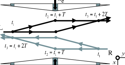
We first briefly review the basic light-pulse method in the case of a symmetric Ramsey-Bordé interferometer scheme Borde02 , where three travelling-wave pulses of light resonantly couple two long-lived electronic states.The two-photon stimulated Raman transitions between ground state hyperfine levels are driven by two lasers with opposite propagation vectors and (). First, at a beam splitting pulse puts the atom into a coherent superposition of its two internal states. Because of conservation of momentum during the atom-light interaction, this pulse introduces a relative momentum between the atomic wave packets corresponding to each state. These wave packets drift apart for a time , after which a mirror pulse is applied at to redirect the two wave packets. After another interval of duration , the wave packets physically overlap, and a final beam splitting pulse recombines them at . The measurement of the probabilities of presence in both internal states at the interferometer output leads to the determination of the difference of accumulated phases along the two paths. In general, atoms are launched with a velocity so that each stimulated Raman transition occurs at a particular position that can be evaluated from the classical trajectories associated with the atomic wave packets Antoine03 , as shown fig. 1. In our setup, Raman laser beams propagate in the (Ox) direction and atoms are launched in the plane. We define = the atomic cloud positions in this plane at time .
In the absence of any external forces, atoms initially prepared in a particular state ( in the present setup) will return to this state with unit probability. A uniform external acceleration or rotation induces a relative phase shift between the interfering paths. This phase shift modifies the transition probability between the two Cesium internal states and (noted and in the following). Hence the transition probability measurement leads to the determination of the phase shift and finally the evaluation of the perturbing forces.
It can be shown that the only contribution to the phase shift results from the interaction with the laser light fields Antoine03 . In the limit of short, intense pulses, the atomic phase shift associated with a transition (resp. ) is + (resp. -), where is the phase difference between the two Raman laser beams. We then find that the transition probability from to at the exit of the interferometer is simply where . The three quantities correspond to the phase imparted to the atoms by the initial beam splitting pulse, the mirror pulse, and the recombining pulse where . The sensitivity to rotation and acceleration arises from the first term and simplifies to and for the present setup. The phase for the pulse at time corresponds to the local phase in the plane due to wavefront distortions of both laser beams111The interferometer is also sensitive to time fluctuations of the Raman laser phases Yver03 . These fluctuations are identical for the two interferometers and disappear from the rotation signal. They will be neglected in this paper.. It induces a residual phase error at the exit of the interferometer .
Acceleration cannot be discriminated from rotation in a single atomic beam sensor, as stated above. This limitation can be circumvented by installing a second, counter-propagating, cold atomic beam (fig. 1) Gustavson98 . When both atomic beams perfectly overlap, the area vectors for the resulting interferometer loops have opposite directions. The corresponding rotational phase shifts have opposite signs while the acceleration phase shifts are identical. Consequently, acceleration is calculated by summing the two interferometer’s phase shifts: ; while taking the difference rejects the contribution of uniform accelerations so that . In addition, the residual phase error vanishes in , but remains in as an absolute phase bias .
However, an imperfect overlapping of the two counter-propagating wavepackets trajectories might lead to an imperfect common mode rejection of the residual phase error in . Thus, a phase bias will appear, where the notations L and R concern the left and right atom interferometers. While the phase bias depends on the local value of the phase at the average position , the phase bias depends on the local phase gradient at the average position with the position offset :
| (1) |
Equation 1 shows that uncorrelated fluctuations of the wavepackets trajectories from shot to shot causes fluctuations of the phase bias, which amplitude depends on the local wavefront slope of the phase. If we consider a perfect control of the launch velocity222We can reach a stability of m.s-1 or better from shot to shot thanks to the moving molasses technique molasses ., fluctuations of trajectories are only due to fluctuations of the initial positions of the atomic clouds. Consequently, we can consider . The phase fluctuation is then simply proportional to the product of the fluctuations of the cloud initial position with the phase gradients . As the phase gradients are time-independent, the Allan variance of the phase is simply:
| (2) |
where and are the Allan variances of the initial horizontal and vertical positions. Eq. 2 shows that the fluctuations of the clouds initial positions, as well as the wavefront quality of the Raman beams, have to be systematically investigated in atomic gyroscopes in order to estimate how it affects its performances.
3 Experimental results
In our setup, the atomic sources are clouds of Cesium atoms, cooled in magneto-optical traps and launched with a parabolic flight (fig. 2). As the initial angle reaches , and the launch velocity m.s-1, the horizontal velocity is m.s-1.
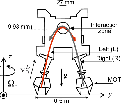
The single pair of Raman laser beams propagates along the x-axis and is switched on three times at the top of the atomic trajectories. If the three pulses are symmetric with respect to the trajectory apogees, the interferometer oriented enclosed areas are equivalent to their flat horizontal projections: the oriented vertical projection is naught. The time delay between pulses is typically ms. The positions of the atoms during the three Raman pulses are given in fig. 2.
In order to investigate the fluctuations of the atomic initial positions from shot to shot, we image one of the two clouds. The cycling sequence takes about 1.3 s and consists on a trap phase of 500 ms, a molasses phase of 20 ms, a launching phase of 2 ms and a waiting time phase of 800 ms needed to process the image: download of the image, subtraction of a background image and determination of the cloud barycenter position in y- and z-axes. The image is taken just after turning off the trap magnetic field, at the end of the molasses phase. We calculate the Allan standard deviations Allan of the barycenter horizontal and vertical positions (fig. 3) from a one hour acquisition. Two peaks, appearing after 10 s and 150 s of integration time, are characteristic of fluctuations of periods equal to 20 s and 300 s. After about 10 min integration (630 s), the position standard deviations reach 10 m and 5 m in the horizontal and vertical directions respectively. This dissymmetry is consistent with the magnetic field gradient configuration, which is twice higher on the Z-direction.
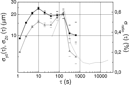
The long-term variations are due to fluctuations of the MOT cooling lasers intensity ratio, which Allan standard deviation is plotted in fig. 3. We see again the oscillation of period 300 s, appearing for 150 s integration time. We analyze this as the period of the air conditioning, creating temperature variations on the fibre splitters delivering the cooling lasers.
This result has to be coupled to the optical aberrations of the Raman lasers. The main contribution to these aberrations comes from the vacuum windows used for the Raman laser beams, which clear diameter is 46 mm. They have been measured with a Zygo wavefront analyzer, which gives the laser phase distortion created by the windows. This distortion is projected on the Zernike polynomial base Zer . As our atomic clouds are about 2 mm wide, the decomposition is pertinent only up to the 36th polynomial. Indeed, the upper numbers correspond to high spatial frequencies, so that their effect will be smoothed by averaging on the atomic cloud dimensions. To reduce the stress on the vacuum windows, essentially due to the mounting, they were glued in place. Thanks to this method, the wavefront quality reaches rms over the whole clear diameter of 42 mm.
The wavefront measurement allows for evaluation of the atomic phase shift fluctuations due to the coupling between aberrations and position fluctuations using eq.2 assuming that the two sources are uncorrelated. Their relative position fluctuations are times greater than these observed for one source. The contribution of this phase fluctuations to the Allan standard deviation of the rotation rate measurement is shown in fig. 4. We compare it with the ultimate stability of our gyroscope, given by the quantum projection noise. It is estimated to nrad.s-1 ( is the integration time) from the ultimate signal-to-noise ratio obtainable with atoms.
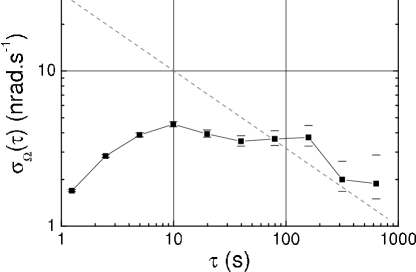
The rotation noise induced by position fluctuations has a significant contribution for integration times larger than 100 s. At the present stage of the experiment, this limitation is due to the high temperature sensitivity of the fibre splitters. This could be the main limitation of the gyroscope performances.
4 Conclusion
In the present paper we studied the stability of a
cold atom gyroscope based on two symmetrical Ramsey-Bordé
interferometers, with respect to optical phase inhomogeneity.
Instability due to aberrations is not a
specific problem induced by Raman transitions, but concerns every
type of atom interferometer using light beam splitters.
We showed that the coupling between wavefront distortions of these lasers and fluctuations of the
atomic trajectory becomes predominant at long term, despite a
wavefront quality of rms obtained thanks to glued
windows. In our setup, atomic trajectory fluctuations are mainly
due to fluctuations of the intensity ratio of the MOT cooling
lasers, induced by the fibre splitters used for their generation.
However several improvements may render their contribution
negligible:
- reduce the atomic trajectory fluctuations, by using discrete optical couplers for the MOT instead of
the present fibre splitters,
- minimize the number of optics which contribute to the interferometer instability. This can be done by including the Raman laser beam
imposition optics in the vacuum chamber, in order to remove the
aberrations due to the vacuum windows, or by minimizing the number
of non-common optics for the two Raman lasers, since only the
phase difference between the lasers is imprinted on the atomic
phase shift.
Such techniques open large improvement possibilities, which will be confirmed directly on the long-term stability measurement of the atomic signal in our interferometer setup.
5 Acknowledgements
The authors would like to thank DGA, SAGEM and CNES for supporting this work, Pierre Petit for the early stage of the experiment and Christian Bordé for helpful discussions. They also thank Thierry Avignon and Lionel Jacubowiez from SupOptique for their help in the wavefront measurement.
References
- (1) F. Riehle, T. Kisters, A. Witte, J. Helmcke and Ch. J. Bordé, Phys. Rev. Lett. 67 (1991) 177 ; M. Kasevich, S. Chu, Phys. Rev. Lett. 67 (1991) 181.
- (2) E. M. Rasel, M. Oberthaler, H. Batelaan, J. Schmiedmayer and A. Zeilinger, Phys. Rev. Lett. 75 (1995) 2633 ; D. M. Giltner, R. W. McGowan and S. A. Lee, Phys. Rev. Lett. 75 (1995) 2638.
- (3) D. W. Keith, C. Ekstrom, Q. A. Turchette and D. E. Pritchard, Phys. Rev. Lett. 66 (1991) 2693.
- (4) Atom Interferometry (ed. Paul R. Berman, London: Academic Press, 1997).
- (5) R. Bingham et al., Assessment Study Report, ESA-SCI (2000) 10.
- (6) Ch. J. Bordé, Laser Spectroscopy X (ed. M. ducloy, E. Giacobino, G. Camy, World Scientific, 1991) 239.
- (7) T. L. Gustavson, A. Landragin, M. A. Kasevich, Class. Quantum Grav. 17 (2000) 1-14.
- (8) A. Peters, K. Y. Chung and S. Chu, Nature 400 (1999) 849.
- (9) J. M. McGuirk , M. J. Snadden and M.A. Kasevich, Phys. Rev. Lett. 85 (2000) 4498-4501-974.
- (10) A. Wicht, J. M. Hensley, E. Sarajlic and S. Chu, in Proceedings of the 6th Symposium on Frequency standards and metrology (ed. Patrick Gill, World Scientific, 2001) 193.
- (11) K. U. Schreiber, A. Velikoseltsev, and M. Rothacher, T. Klügel, G. E. Stedman and D. L. Wiltshire 60 (1997) 615. J. Geophis Res., 109 (2004), B06405, doi:10.1029/2003JB002803.
- (12) F. Yver-Leduc, P. Cheinet, J. Fils, A. Clairon, N. Dimarcq, D. Holleville, P. Bouyer, A. Landragin., J. Opt. B: Quantum Semiclass. Opt. 5 (2003) S136-S142.
- (13) T. L. Gustavson, P. Bouyer, M. A. Kasevich, Proc. SPIE 3270 (1998) 62.
- (14) T. Trebst, T. Binnewies, J. Helmcke, and F. Riehle, I.E.E.E. Trans. on Inst. and Meas. 50 (2001) 2165-2170.
- (15) Ch. J. Bordé, in Advances in the Interplay between Quantum and Gravity Physics (ed. V. de Sabbada, Kluwer, Academic Publisher, 2001)
- (16) C. Antoine, Ch. J. Bordé, Phys. Lett. A 306 (2003) 277.
- (17) A. Clairon, C. Salomon, S. Guellati and W. Phillips, Europhys. Lett. 16 (1991) 165.
- (18) D. W. Allan, Proc. IEEE 54 (1966) 221.
- (19) M. Born and E. Wolf, Principles of Optics (Pergamon Press, fifth edition, 1975).