Cavity-enhanced single frequency synthesis via DFG of mode-locked pulse trains
Abstract
We show how to synthesize a CW, single-frequency optical field from the frequency-dispersed, pulsed field of a mode-locked laser. This process, which relies on difference frequency generation in an optical cavity, is efficient and can be considered as an optical rectification. Quantitative estimates for the output power and amplitude noise properties of a realistic system are given. Possible applications to optical frequency synthesis and optical metrology are envisaged.
I Introduction
The introduction of Kerr-lens mode-locked lasers (KLML) as referenced optical frequency synthesizers Diddams2000 ; Udem2002 represents a milestone in optical frequency synthesis. Before the advent of KLML, optical frequency synthesis and measurements were generally performed through harmonic generation in frequency chains Jennings1983 ; Schnatz1996 relying on involved apparatuses. In addition, only narrow portions of the optical spectrum were accessible. Alternative techniques of frequency interval bisection Telle1990 ; Udem1997 and optical comb generators Kourogi1993 ; Kourogi1996 simplified to some extent the task of synthesizing optical frequencies, but still could not provide a single instrument to cover the whole optical spectrum from the visible to the near infra-red.
By providing a wide ruler of well spaced optical frequencies, KLML now represent the best solution to measure and synthesize optical frequencies ranging from the near IR to most of the visible. These lasers have a spectrum composed by a comb of frequencies , where is the repetition rate of the pulsed laser, is the carrier envelope offset frequency, and is an integer Cundiff2001 . On one hand, optical frequency measurements are performed by measuring the beat note between the optical frequency to be measured and the closest tooth of the KLML comb, and then determining the integer from a rough wavelength measure. On the other hand, an optical frequency can be synthesized by locking the frequency of a continuous wave optical field to a tooth of the KLML comb.
From the practical point of view, such optical measurements depend critically on two issues: the determination and stabilization of the comb parameters and , and the amount of power available at the frequency component closest to the one of the laser field to be measured Hollberg2001 . While is directly available from the amplitude modulation of the KLML, the determination and stabilization of , typically known as self-referencing, involves delicate manipulation of the ultra-broadband light, e.g. by means of nonlinear optical processes such as frequency doubling of the red tail of the spectrum and its beating with the blue tail Cundiff2001 or even more complex schemes, as discussed in Telle1999 .
This, in turn, requires the use of octave-spanning sources such as Ti:Sa femto-second lasers spectrally broadened through micro-structured fibers Ranka2000 , or ultra-broadband femto-second lasers Ramond2002 . From the point of view of the power available on the frequency component of interest, self-referenced comb generators were demonstrated to have a suitable spectrum to measure frequencies in the wavelength range from 500 nm up to 2 m Cundiff2001 ; Thomann2003 . The region of optimal sensitivity for the measurement depends on the frequency comb spectral envelope and therefore on the nature of the medium used to generate the ultra-broadband spectrum Hollberg2001 .
II Cavity-assisted rectification: general idea
We propose a different approach to directly synthesize optical fields from mode-locked lasers. The basic idea consists in the conversion of the comb of frequency components present in a mode-locked laser into a single frequency component . The idea can be implemented to devise an optical rectifier that efficiently converts a pulsed light source into a monochromatic continuous wave optical field. Two regions of the spectrum of a mode-locked laser are sent through a non-linear crystal so as to generate radiation via difference frequency generation (DFG). The nonlinear polarization in the crystal is composed by a comb of frequency which are integer multiples of the repetition rate . An optical cavity surrounds the non-linear crystal and is resonant with the polarization component at frequency , while all other components are off-resonance with respect to all cavity modes. In these conditions, the polarization mode at solely contributes to the field circulating in the cavity, hence a nearly monochromatic radiation is generated with a power proportional to the finesse of the cavity. This results in a power on the component at orders of magnitude higher than the one that would be obtained by means of a simple frequency filtering of the radiation generated by a single-pass DFG. Moreover, the suppression of all non resonant components by the action of the cavity results in a significant reduction of the amplitude noise spectrum.
III Theoretical model
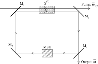
Consider a ring cavity of total length containing a slab of nonlinear medium of length , as sketched in fig.1. The cavity mirrors are assumed to be perfectly transmitting for the source laser light so as to avoid the need of matching the cavity spectral range with the comb spacing, but highly reflecting at the of the radiation to be generated so as to take advantage of resonance effects at . Here, the reflectivity of three mirrors will be taken exactly 1, while the fourth one will have a finite but small transmission and will be considered as the output of the system.
The source beam consists of a train of ultrashort pulses
| (1) |
where describes the shape of each pulse, is the temporal spacing of the pulses and is their relative phase. In Fourier space this train of pulses corresponds to a comb of -function peaks
| (2) |
at equispaced frequencies , where is the comb spacing and is the carrier envelope offset. The comb envelope is the Fourier transform of the single pulse profile , which is centered at the carrier frequency and has a width of the order of the inverse of the single pulse duration .
Since we are interested in generating light at a given frequency , two spectral sections of the comb are selected centered at and , respectively, and such that their difference is close to . In the following, we shall see that the width of the two sections is limited by the acceptance bandwidth of the nonlinear crystal as well as by the different group velocity of the two sub-pulses at during the propagation towards the crystal, i.e. the dephasing of the different teeth within each of the two sections. Concerning the latter point, dispersion can be compensated with standard techniques such as chirped mirrors and/or negatively dispersing optical elements, while for the dispersion in the nonlinear crystal the acceptance bandwidth is directly obtained from data available in literature. We will discuss in the following a possible experimental realization.
We start by assuming a constant nonlinear susceptibility of the crystal equal to , and we neglect source depletion and reflections at the crystal interfaces. As the relative phase between the different teeth within each of the two sections around is assumed to be negligible, the nonlinear polarization inside the crystal can be written as:
| (3) |
where is the linear refractive index of the nonlinear medium at and is the corresponding wave vector; is assumed to be real at all frequencies of interest; the indices and run over the frequency components of the comb. The Fourier transform of (3) is a comb of -function peaks spaced of with a vanishing offset. The amplitude of the component at the frequency is given by the sum over all pairs such that .
The steady-state amplitude of the cavity field is obtained by solving the wave equation with the source term corresponding to the nonlinear polarization (3). As the calculation is somewhat lengthy, the details are given in the Appendix A, and we here discuss the final result only. The frequency spectrum of the cavity field has the same discrete structure of the nonlinear polarization. On the internal side of the output mirror, the amplitude of the component has the explicit expression:
where the optical length of the cavity is defined as usual as and gives the position of the front interface of the crystal.
The denominator of the first fraction on the RHS accounts for resonance effects due to the presence of the cavity whose modes are determined by the usual round-trip condition ( integer). For a weak transmittivity of the output mirror, and in the absence of significant losses in the cavity, the damping rate of the cavity modes is determined by the finite transmittivity of the output mirror . The fraction in the sum takes into account the phase-matching effects associated with the refractive index dispersion of the nonlinear crystal. Because of dispersion, the polarization at produced by the different pairs has a different wave vector . This wave vector has to be close to the one of the radiation to be generated for the DFG process to be efficient.
Physical insight on the spectrum of the generated light can be found by rewriting the amplitude of the output beam in terms of the field that would be generated by the same crystal in a single-pass geometry. The same calculations (see Appendix A) that led to (III) give the following expression:
| (5) |
For , one sees that the output power which is obtained under the resonance condition is a factor larger than the one that would be obtained in a single-pass geometry. If the non-radiative cavity losses are not negligible, the output power is a factor weaker.
IV Illustrative examples
As we are interested in obtaining a single-frequency output beam, a single tooth out of the comb of frequencies actually present in the nonlinear polarization spectrum has to be singled out by the action of the cavity. This has therefore to be designed in such a way that only the component at the desired frequency is on resonance with a cavity mode, while all the others, being off-resonance, are suppressed. To this purpose, several strategies can be adopted. The most trivial one consists in choosing the cavity free spectral range and the repetition rate of the source laser to be non-commensurate to avoid multiple exact resonances HighFinesse . Another option is, in analogy with standard laser techniques, to insert in the cavity some frequency discriminators, like Fabry-Perot etalons, which introduce additional losses to suppress unwanted resonances keeping the resonant enhancement only for the mode of interest.
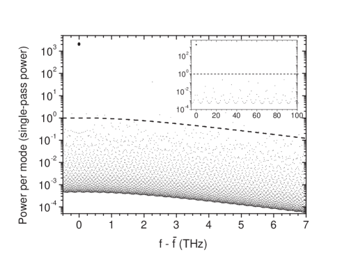
As an illustrative example, we consider a resonator with a free spectral range (FSR) of 1,13 GHz pumped by a femtosecond laser with a repetition rate of 1 GHz and containing two uncoated glass etalons 410 m and 2.2 mm thick. The two etalons have unity transmission at , and the finesse of the cavity is 1570 and limited by the transmissivity of the output mirror =0.2%. The polarization of the non-linear crystal is a profile with FWHM of 6.4 THz and centered on . Figure 2 represents the output spectrum for these specific parameter values with the optical power normalized to field at generated in single-pass DFG. The inset shows that the resonator not only enhances the component at but also suppresses the power on most of the other, non-resonant, components. With the parameters considered here, the power at is increased by a factor 2000 with respect to the single-pass conversion, and the sum of the power on all non-resonant modes amounts to 13 % of that at . This means that the output is indeed a continuous wave field at frequency superposed to a small, amplitude modulation at frequency and its higher harmonics with a bandwidth of the order of the frequency spread of the DFG polarization, of the order of .
Giving a realistic estimate of the power generated by the optical rectifier requires stringent assumptions on the experimental parameters ExperimentalAssumptions . We examine, for instance, the case in which the optical rectifier synthesizes radiation at 2.8 m. We consider the spectral windows at 680 and 900 nm form a mode-locked laser, each having a spectral width of 3 THz equal to the acceptance bandwidth of the non-linear crystal. Supposing that the model-locked laser has 1 GHz repetition rate and delivers both at 680 and 900 nm 30 pJ per pulse Ramond2002 , that the non-linear medium is a 1 mm crystal of periodically poled lithium niobate (PPLN), neglecting losses Myers1996 , then the single-pass DFG energy can be estimated to be of 0.2 pJ per pulse. With the given repetition rate =1 GHz and spectral width for the envelope of the DFG radiation, the peak single-pass conversion to 2.8 m is about 35 nW per frequency component. The use of the optical rectifier increases the output power at to 70 W. This value is comparable Borri2003 or larger Fuji2004 than the power produced by alternative systems with analogous spectral characteristics.
V Discussion
Let’s now summarize the main advantages offered by the proposed optical rectifier as a frequency synthesizer of continuous wave optical fields. It is well known that the frequency components generated by DFG between separate spectral regions of one mode-locked laser depend only on the repetition rate and not on the carrier envelope offset frequency . This makes its stabilization unnecessary and therefore reduces the complexity of the system.
Another common feature of DFG processes with mode-locked lasers is that the amplitude at the frequency is not determined by a single pair, but from the constructive interference of all the pairs that lie within the acceptance window of the nonlinear crystal . If we denote by the pair of components which gives exact phase matching and we linearize the dispersion of the refractive index around its values respectively at and , the number of pairs which are actually phase matched can be estimated to be of the order of:
| (6) |
The power of the generated beam is therefore a factor larger than the one that would be generated by a single pair.
In our cavity-enhanced set-up, the power of the generated light is further enhanced by a factor proportional to the finesse. Moreover, suppressing the power on all frequency components available from the polarization but , the optical rectifier allows for a strong reduction on the amplitude modulation of the generated field. This results into a reduction of the noise spectrum of the beatnote signal between the synthesized frequency and that to be measured Hollberg2001 . This should lead to high contrast measurements even with relatively weak fields.
In conventional lasers the coherence properties of the generated light are determined by the spontaneous symmetry breaking induced by coupling between the cavity and the gain medium LaserRef . However, it is worth noting that in our optical rectifier the coherence properties of the output are determined by the ones of the mode-locked laser and, in particular, through its repetition rate. The cavity plays only the role of selector among the pairs of frequencies allowed by difference frequency generation, enhancing one single frequency while suppressing the others.
From the practical point of view, the spectrum of the pumping mode-locked laser has to be taken into account in the choice of the cavity parameters. Neglecting all cavity losses but the output mirror, equation (5) shows that output power increases as . This holds true in the most usual case when the linewidth of each frequency component of the mode-locked laser is narrower than the linewidth of the cavity mode. By increasing the finesse of the cavity beyond this condition one can easily prove that the circulating power now increases proportionally to 1/T, while the output power tends to a constant.
VI Conclusions
In conclusion, we presented a novel scheme for synthesizing continuous wave and single-frequency optical beams from pulsed mode-locked lasers. We believe that this scheme for optical rectification holds promises for applications to optical frequency metrology and direct synthesis of CW optical fields from radiofrequencies. The continuous wave optical synthesizer would be composed by a mode-locked laser spanning the spectral regions to pump the DFG, with the repetition rate stabilized to a radiofrequency reference, followed by the optical rectifier tuned to the frequency to be generated.
Acknowledgments
We thank M. Artoni, R.E. Drullinger, G. Giusfredi, D. Mazzotti, and G.M. Tino for stimulating discussions. Laboratoire Kastler Brossel is a unité de Recherche de l’Ecole Normale Supérieure et de l’Université Pierre et Marie Curie, associée au CNRS.
References
- (1) S.A. Diddams, D.J. Jones, J. Ye, S.T. Cundiff, J.L. Hall, J.K. Ranka, R.S. Windeler, R Holzwarth, T. Udem, and T.W. Hänsch, “Direct Link between Microwave and Optical Frequencies with a 300 THz Femtosecond Laser Comb”, Phys. Rev. Lett. 84, 5102–5105 (2000).
- (2) T. Udem, R. Holzwarth, and T.W. Hänsch, “Optical frequency metrology”, Nature 416, 233-237 (2002).
- (3) D.A. Jennings, C.R. Pollock, F.R. Petersen, R.E. Drullinger, K.M. Evenson, J.S. Wells, J.L. Hall, and H.P. Layer, “Direct frequency measurement of the I2-stabilized He-Ne 473-THz (633-nm) laser”, Opt. Lett. 8, 136–138 (1983).
- (4) H. Schnatz, B. Lipphardt, J. Helmcke, F. Riehle, G. Zinner, “First Phase-Coherent Frequency Measurement of Visible Radiation”, Phys. Rev. Lett. 76, 18–21 (1996).
- (5) H.R. Telle, D. Meschede, and T.W. Hänsch, “Realization of a new concept for visible frequency division: phase locking of harmonic and sum frequencies”, Opt. Lett 15, 532–534 (1990).
- (6) T. Udem, A. Huber, B. Gross, J. Reichert, M. Prevedelli, M. Weitz, and T.W. Hänsch, “Phase-Coherent Measurement of the Hydrogen 1S-2S Transition Frequency with an Optical Frequency Interval Divider Chain”, Phys. Rev. Lett. 79, 2646–2649 (1997).
- (7) M. Kourogi, K. Nakagawa, and M. Ohtsu, “Wide-span optical frequency comb generator for accurate optical frequency difference measurement”, IEEE J. Quant. Electron 29, 2693–2701 (1993).
- (8) K. Nakagawa, M. de Labachelerie, Y. Awaji, and M. Kourogi, “Accurate optical frequency atlas of the 1.5-m bands of acetylene”, J. Opt. Soc. Am. B 13, 2708–2714 (1996).
- (9) S.T. Cundiff, J. Ye., and J.L. Hall, “Optical frequency synthesis based on modelocked lasers”, Rev. Sci. Instrum. 72, 3749–3771 (2001), and references therein.
- (10) H.R. Telle, G. Steinmeyer, A.E. Dunlop, J. Stenger, D.H. Sutter, U. Keller, “Carrier-envelope offset phase control: A novel concept for absolute optical frequency measurement and ultrashort pulse generation”, Appl. Phys. B 69, 327–332 (1999).
- (11) L. Hollberg, C.W. Oates, E.A. Curtis, E.N. Ivanov, S.A. Diddams, Th. Udem, H.G. Robinson, J.C. Bergquist, W.M. Itano, R.E. Drullinger, and D.J. Wineland , “Optical Frequency Standards and Measurements”, IEEE J. Quantum Electron. 37, 1502–1513 (2001).
- (12) J.K. Ranka, R.S. Windeler, and A.J. Stentz, “Visible continuum generation in air silica microstructure optical fibers with anomalous dispersion at 800nm”, Opt. Lett. 25, 25–27 (2000).
- (13) T. Ramond, S.A. Diddams, L. Hollberg, and A Bartels, “Phase-coherent link from optical to microwave frequencies by means of the broadband continuum from a 1-GHz Ti:sapphire femtosecondoscillator”, Opt. Lett. 27, 1842–1844 (2002).
- (14) I. Thomann, A. Bartels, K.L. Corwin, N.R. Newbury, L. Hollberg, S.A. Diddams, J.W. Nicholson and M.F. Yan, “20-MHz Cr:forsterite femtosecond ring laser and continuum generation in the 1-2 m range”, Opt. Lett. 28, 1368–1370 (2003).
- (15) This approach requires a finesse suffuciently high to avoid the contribution of cavity modes close to unwanted resonances and may result in very high finesse cavities.
- (16) The detailed spectrum of a mode locked laser depends critically on the dispersion properties of its cavity, and eventually those of medium employed to broaden its spectrum.
- (17) L.E. Myers, R.C. Eckardt, M.M. Fejer, R.L. Byer, and W.R. Bosenberg, “Multigrating quasi-phase-matched optical parametric oscillator in periodically poled LiNbO3”, Opt. Lett. 21, 591–593 (1996).
- (18) P. De Natale, S. Borri, P. Cancio, G. Giusfredi, D. Mazzotti, M. Prevedelli, C. De Mauro, and M. Inguscio, “Extending the optical comb synthesizer to the infrared: from He at 1.083 m to CO2 at 4.2 m”, in Proceedings of the 16th International Conference on Laser Spectroscopy (ICOLS 2003), P. Hannaford, A. Sidorov, H. Bachor, and K. Baldwin eds. (World Scientific, Singapore 2004), pp. 63-67.
- (19) T. Fuji, A. Apolonski, and F. Krausz, “Self-stabilization of carrier-envelope offset phase by use of difference-frequency generation”, Opt. Lett. 29, 632–634 (2004).
- (20) A.E. Siegman, Lasers (Oxford University Press, Oxford, 1986).
- (21) R.W. Boyd, Nonlinear Optics (Academic Press, London, 1992).
- (22) P.N.Butcher and D.Cotter, The elements of nonlinear optics (Cambridge Univ.Press, 1993).
Appendix A Solution of the wave equation
The purpose of this appendix is to give some details about the calculations that lead to the expression (III) for the in-cavity field generated by the nonlinear polarization of the medium.
As Maxwell’s equations are linear, we can calculate the emitted field separately for each pair such that which then contributes to the polarization at the frequency of interest. The final result (III) will be the sum of all these contibutions. From now on all quantities are to be considered as Fourier components at the frequency of the corresponding quantity. The spatial coordinate goes around the cavity; let correspond to the output mirror, and the nonlinear medium extend from to .
The general solution of Maxwell’s equation in the free-space outside the nonlinear medium has the usual plane-wave form:
| (7) |
There is no need for taking into account the counterpropagating wave thanks to the assumption of negligible reflections at the nonlinear medium interfaces. The general solution (8) has to be applied in the two regions outside the crystal and , where the field can be respectively written as
| (8) |
being parameters to be determined later.
Using the explicit expression for nonlinear polarization of the nonlinear medium:
| (9) |
the inhomogeneous wave equation inside the nonlinear medium has the form:
| (10) |
where gives the spatial dependence of the nonlinear polarization, its amplitude, is the linear refractive index of the nonlinear medium at the frequency , and the corresponding wavevector Boyd ; ButcherCotter .
The parameters and can be determined by imposing the appropriate boundary conditions at the interface between the free-space and the nonlinear medium and at the cavity mirrors.
As reflections at the nonlinear medium interface have been taken as negligible, the energy flux is conserved across the interface. This imposes that:
| (12) | |||||
| (13) |
Assuming for simplicity a vanishing reflection phase for the cavity mirrors, the electric field is continuous at the three perfectly reflecting ones, while at the fourth, output, mirror one has the boundary condition:
| (14) |
where the electric fields at are respectively the incident and reflected fields, and is the mirror transmittivity.
By imposing the three conditions (12,13,14) onto the general solutions (8) and (11) of the wave equations in the nonlinear medium and in the two regions of free space, one obtains explicit expressions for the three parameters and .
In particular, we are interested in the amplitude of the in-cavity field just before the output mirror:
| (15) |
the effective optical length being defined as . Summing over all the pairs , one finally obtains the expression (III).
From the general solution of the wave equation (11) inside the medium, it is immediate to obtain the amplitude of the field generated in a single-pass configuration. One has to fix by imposing that the field vanishes at the front interface and then evaluate the corresponding value of the field at the exit interface:
| (16) |
from which the generated field in a single-pass geometry is immediately obtained using the boundary condition (13):
| (17) |
The relation (5) is then simply obtained by comparing (15) and (17). Note that (17) could be obtained from (15) simply by imposing that a full transmission of the output mirror .