Diffraction-Attenuation Resistant Beams
in
Absorbing Media ††footnotetext: Work
partially supported by FAPESP (Brazil).
E-mail address for
contacts: mzamboni@dmo.fee.unicamp.br
Michel Zamboni-Rached,
DMO–FEEC, State University at Campinas, Campinas, SP, Brazil.
Abstract
In this work, in terms of suitable superpositions of equal-frequency Bessel beams, we develop a theoretical method to obtain nondiffractive beams in (weakly conductive) absorbing media capable to resist the loss effects for long distances.
PACS nos.: 41.20.Jb ; 03.50.De ; 03.30.+p ; 84.40.Az ; 42.82.Et ; 83.50.Vr ; 62.30.+d ; 43.60.+d ; 91.30.Fn ; 04.30.Nk ; 42.25.Bs ; 46.40.Cd ; 52.35.Lv .
1 Introduction
Over many years, the theory of nondiffracting beams and pulses has been developed, generalized and experimentally verified in many fields, such as optics, microwaves and acoustics[1-11].
When propagating in a non-absorbing medium, these waves maintain their spatial shape for long distances, i.e., they possess a large depth of field.
However, the situation is not the same when dealing with absorbing media. In these cases, both the ordinary and the nondiffracting beams (and pulses) will suffer the same effect: an exponential attenuation along the propagation axis.
Here, we are going to show that, through suitable superpositions of equal-frequency Bessel beams, it is possible to obtain nondiffracting beams in absorbing media capable to resist the loss effects, maintaining amplitude and spot size of their central core for long distances.
The method that will be developed here is a generalization of a previous one (also developed by us)[12, 13], which was conceived for lossless media, where suitable superpositions of Bessel beams are used to construct stationary wave fields with arbitrary longitudinal intensity shape. Those new solutions were called Frozen Waves.
Before continuing, some points are to be stressed: (a) the method developed here addresses to poorly conductive media () in the optical frequency range; actually, we are considering materials where the penetration depth of the optical beams are typically m; (b) the energy absorption by the medium continues to occur normally, the difference being in that these new beams have an initial transverse field distribution, such to be able to reconstruct (even in the presence of absorption) their central cores for distances considerably longer than the penetration depths of ordinary (nondiffracting or diffracting) beams.
2 The Mathematical Methodology
The method that will be developed in this Section is based on Bessel beams superpositions; so, it is appropriate first to recall some characteristics of such beams in absorbing media.
In the same way as for lossless media, we construct a Bessel beam in the absorbing materials by superposing plane waves whose wave vectors lie on the surface of a cone with vertex angle . The refractive index of the medium can be written as , quantity being the real part of the complex refraction index and the imaginary one, responsible for the absorbing effects. With a plane wave, the penetration depth for the frequency is given by .
In this way, a zero-order Bessel beam in dissipative media can
be written as
with ;
, and so . In this way , where , are the real parts of the
longitudinal and transverse wave numbers, and , are the imaginary ones, while the absorption coefficient of a
Bessel beam with an axicon angle is given by
, its penetration
depth being .
Due to the fact that is complex, the amplitude of the Bessel function starts decreasing from till the transverse distance , and afterwards it starts growing exponentially. This behavior is not physically acceptable, but one must remember that it occurs only because of the fact that an ideal Bessel beam needs an infinite aperture to be generated. However, in any real situation, when a Bessel beam is generated by finite apertures, that exponential growth in the transverse direction, starting after , will not occur indefinitely, stopping at a given value of . Actually, taking into account the size of the aperture generally used for generating optical Bessel beams, and the fact that we are considering media that are poor conductors, that exponential growth does not even happen, and the resulting Bessel beam only presents a decreasing intensity in the transverse direction.
Let us now present our method.
Consider an absorbing medium with the complex refraction index , and the following superposition of Bessel beams with the same frequency
| (1) |
where are integer numbers, are constant (yet unknown) coefficients, and ( and ) are the real parts (the imaginary parts) of the complex longitudinal and transverse wave numbers of the m-th Bessel beam in superposition (1), the following relations being satisfied
| (2) |
| (3) |
| (4) |
where and .
Our goal is now to find out the values of the longitudinal wave numbers and the coefficients in order to reproduce approximately, inside the interval (on the axis ), a freely chosen longitudinal intensity pattern that we call .
The problem was already solved by us and the method developed for the particular case of lossless media[12, 13], i.e., when . For those cases, it was shown that the choice , with can be used to provide approximately the desired longitudinal intensity pattern on the propagation axis, within the interval , and, at same time, to regulate the spot size of the resulting beam by means of the parameter , which can be also used to obtain large field depths (see details in Refs.[12, 13]).
However, when dealing with absorbing media, the procedure described in the last paragraph does not work, due to the presence of the functions in the superposition (1), since in this case that series does not became a Fourier series when .
On attempting to overcome this limitation, let us write the real part of the longitudinal wave number, in superposition (1), as
| (5) |
with
| (6) |
where this inequality guarantees forward propagation only, with no evanescent waves.
In this way the superposition (1) can be written
| (7) |
where, by using Eqs.(3), quantity is given by
| (8) |
and is given by Eq.(2).
Now, let us examine the imaginary part of the longitudinal wave numbers. From Eq.(8) the minimum and maximum values among the are and , the central one being given by . With this in mind, let us evaluate the ratio
| (9) |
Thus, when , there are no considerable differences among the various , since it holds for all . And, in the same way, there are no considerable differences among the exponential attenuation factors, since . So, when the series in the r.h.s. of Eq.(7) can be approximately considered a truncated Fourier series multiplied by the function : and, therefore, superposition (7) can be used to reproduce approximately the desired longitudinal intensity pattern (on ), within , when the coefficients are given by
| (10) |
the presence of the factor in the integrand being necessary to compensate for the factors in superposition (7).
Since we are adding together zero-order Bessel functions, we can expect a good field concentration around .
In short, we have shown in this Section how one can get, in a weakly conductive absorbing medium, a stationary wave-field with a good transverse concentration, and whose longitudinal intensity pattern (on ) can approximately assume any desired shape within the predetermined interval . The method is a generalization of a previous one[12, 13] and consists in the superposition of Bessel beams in (7), the real and imaginary parts of their longitudinal wave numbers being given by Eqs.(5)and (8), while their complex transverse wave numbers are given by Eq.(2), and, finally, the coefficients of the superposition are given by Eq.(10). The method is justified, since ; happily enough, this condition is satisfied in a great number of situations.
In the next Section we shall apply this method for obtaining new beams whose central core can resist the effects caused by diffraction and attenuation in absorbing media for long distances.
3 Examples: Almost Undistorted Beams in Absorbing Media
Let us consider a biological tissue as the absorbing medium. In the wavelength range nm, proteins are the major absorbers, being the UV absorption similar for many types of tissues.
A typical XeCl excimer laser (Hz) has a penetration depth, in this case, of 5 cm; i.e., an absorption coefficient , and therefore . The real part of the refraction index for this wavelength can be approximated by , and therefore .
A typical Bessel beam with Hz and with an axicon angle rad (so, with a transverse spot of radius m), when generated by an aperture, say, of radius mm, can propagate in vacuum a distance (its field depth) equal to cm while resisting the diffraction effects. However, in the material medium considered here, the penetration depth of this Bessel beam would be only cm.
Now, we can use the method of the previous Section to obtain, in the same medium and for the same wavelength, an almost undistorted beam capable of preserving its spot size and the intensity of its central core for a distance many times larger than the typical penetration depth of an ordinary beam (nondiffracting or not).
With this purpose, let us suppose that, for this material medium, we want a beam (with Hz) that maintains amplitude and spot size of its central core for a distance of cm, i.e., a distance 5 times greater than the penetration depth of an ordinary beam with the same frequency. We can model this beam by choosing the desired longitudinal intensity pattern (on ), within ,
| (11) |
and by putting cm, with, for example, cm.
Now, the Bessel beam superposition (7) can be used to reproduce approximately this intensity pattern, and to this purpose let us choose for the in Eq.(5), and (which is allowed by inequality (6)).
Once we have chosen the values of , and , the values of the complex longitudinal and transverse Bessel beams wave numbers happen to be defined by relations (5), (8) and (2). Eventually, we can use Eq.(10) and find out the coefficients of the fundamental superposition (7), that defines the resulting stationary wave-field.
Let us just note that the condition is perfectly satisfied in this case.
In Fig.1(a) we compare the desired longitudinal intensity function with the resulting stationary wave field, obtained from the Bessel beam superposition (7), and we can notice a good agreement between them. A better result could be reached by using a higher value of , which in this specific example may assume, according to inequality (6), a maximum value of .
It is interesting to note that. at this distance (25 cm), an ordinary beam would have got its initial field-intensity attenuated times.
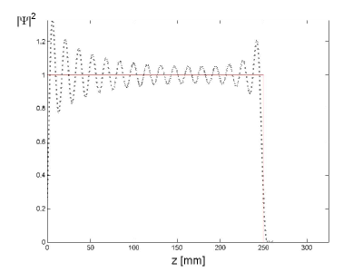
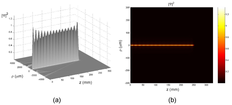
Figure 2(a) shows the 3D field-intensity of the resulting beam. One can see that the field possesses a good transverse localization (with a spot size smaller than m), it being capable of maintaining spot size and intensity of its central core till the desired distance. Figure 2(b) shows the same picture, but in an orthogonal projection.
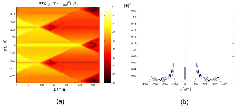
As we have said in the Introduction, the energy absorption by the medium continues to occur normally; the difference is that these new beams have an initial transverse field distribution sophisticated enough to be able to reconstruct (even in the presence of absorption) their central cores till a certain distance. For a better visualization of this field-intensity distribution and of the energy flux, Fig.3(a) shows the resulting beam, in an orthogonal projection and in logarithmic scale. It is clear that the energy comes from the lateral regions, in order to reconstruct the central core of the beam. Figure 3(b) presents the initial field-intensity distribution on the aperture plane, at . We can note the complicated initial transverse field-intensity distribution needed for feeding the central core of the beam along the propagation axis.
Obviously, the amount of energy necessary to construct these new beams is greater than that necessary to generate an ordinary beam in a non-absorbing medium.
And it is also clear that there is a limitation on the depth of field of these new beams. For distances longer than 8 or 10 times the penetration depth of an ordinary beam, besides a great energy demand, we meet the fact that the field-intensity in the lateral regions would be even higher than that of the core, and the field would loose the usual characteristics of a beam (transverse field concentration).
4 Conclusion
In this paper we have shown that it is possible to construct almost-undistorted beams in absorbing media. They are got by suitable Bessel beams superpositions, and are capable to resist the loss effects, maintaining amplitude and spot size of their central core for long distances, when compared with the usual penetration depths of ordinary beams.
5 Acknowledgements
The author is very grateful to Erasmo Recami, Hugo E. Hernández-Figueroa and Claudio Conti for continuous discussions and kind collaboration.
References
- [1] J. Durnin, J. J. Miceli and J. H. Eberly, “Diffraction-free beams,” Physical Review Letters 58, 1499-1501 (1987).
- [2] I. M. Besieris, A. M. Shaarawi and R. W. Ziolkowski, “A bi-directional traveling plane wave representation of exact solutions of the scalar wave equation,” J. Math. Phys. 30, 1254-1269 (1989).
- [3] J.-Y. Lu and J. F. Greenleaf,“Nondiffracting X-waves: Exact solutions to free-space scalar wave equation and their finite aperture realizations,” IEEE Trans. Ultrason. Ferroelectr. Freq. Control 39, 19-31 (1992).
- [4] P. Saari and K. Reivelt, “Evidence of X-shaped propagation-invariant localized light waves,” Phys. Rev. Lett. 79, 4135-4138 (1997).
- [5] E. Recami, “On localized X-shaped Superluminal solutions to Maxwell equations”, Physica A 252, 586-610 (1998), and refs. therein.
- [6] D. Mugnai, A. Ranfagni and R. Ruggeri, “Observation of superluminal behaviors in wave propagation,” Phys. Rev. Lett. 84, 4830-4833 (2000). This paper aroused some criticisms, to which the authors replied.
- [7] M. Zamboni-Rached, E. Recami and H. E. Hernández-Figueroa, “New localized Superluminal solutions to the wave equations with finite total energies and arbitrary frequencies,” European Physical Journal D 21, 217-228 (2002).
- [8] For a review, see: E. Recami, M. Zamboni-Rached, K. Z. Nóbrega, C. A. Dartora, and H. E. Hernández-Figueroa, “On the localized superluminal solutions to the Maxwell equations,” IEEE Journal of Selected Topics in Quantum Electronics 9, 59-73 (2003), and refs. therein.
- [9] S. Longhi, “Spatial-temporal Gauss-Laguerre waves in dispersive media”, Physical Review E, 68, article no.066612 (2003).
- [10] M. A. Porras, S. Trillo, C. Conti, and P. Di Trapani, “Paraxial envelope X waves”, Optics Letters, 28, 1090-1093 (2003).
- [11] C. Conti, and S. Trillo, “X waves generated at the second harmonic”, Optics Letters, 28, 1251-1253 (2003).
- [12] M. Zamboni-Rached, “Stationary optical wave fields with arbitrary longitudinal shape by superposing equal frequency Bessel beams: Frozen Waves,” Optics Express 12, 4001-4006 (2004).
- [13] M. Zamboni-Rached, E. Recami and H. E. Hernández-Figueroa “Theory of Frozen Waves: Modelling the Shape of Stationary Wave Fields,” J. Opt. Soc. Am., A, (to be published).