Dynamics of a bouncing dimer
Abstract
We investigate the dynamics of a dimer bouncing on a vertically oscillated plate. The dimer, composed of two spheres rigidly connected by a light rod, exhibits several modes depending on initial and driving conditions. The first excited mode has a novel horizontal drift in which one end of the dimer stays on the plate during most of the cycle, while the other end bounces in phase with the plate. The speed and direction of the drift depend on the aspect ratio of the dimer. We employ event-driven simulations based on a detailed treatment of frictional interactions between the dimer and the plate in order to elucidate the nature of the transport mechanism in the drift mode.
pacs:
05.45.-a, 45.70.-n, 47.52.+jThe shape of grains has a fundamental impact on static and dynamic properties of granular materials. Packing of granular material is affected by the relative orientation of grains packing , the statistics of avalanching is apparently different in regular sandpiles and piles of elongated rice SOC , and strongly shaken rods exhibit self-organization which leads to formation of large vortices blair03 ; aranson03 . Thus the phenomenology of asymmetric grains is very different from that of spherical beads and irregularly shaped sand.
In Ref. volfson04 , using a combination of theory and experiments in a quasi-2D geometry (vibrated rods in an annulus), we showed that the motion of rods is caused by the non-eccentric frictional collisions between the rods and the vibrated plate. These collisions are translated into collective motion by multiple non-elastic collisions among the rods during the flights between rod-plate collisions. In this paper, we focus on an even simpler case of a single anisotropic “grain” on an oscillated plate in order to study mechanisms of transformation of vibrational excitation into horizontal transport in the absence of externally imposed asymmetry. Recent studies of thermal ratchets have addressed the more straightforward situation where there is an imposed left/right asymmetry in the substrate derenyi98 .
In contrast with our previous work with thin rods, here we study the dynamics of a rigid dimer consisting of two heavy spheres connected by a light rod. Unlike the rods case, the points of contact with the plate are easily determined even when the dimer is horizontal at the time of collision (in this case, there are two well defined contact points). We also note that the oscillated dimer can serve as a natural generalization to the much studied system of a particle on a vibrated plate which is a paradigm for period doubling and transition to chaos tufillaro92 . As we show here, in addition to those regimes, the oscillated dimer displays spontaneous symmetry breaking and ratchet-like transport in a system without externally imposed asymmetry.
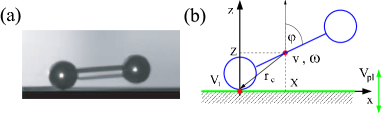
Figure 1 shows a photo and a schematic diagram of the system. The experiments reported here are performed with dimers fabricated with steel spheres with a diameter of 9.5 mm, and a glass rod with a 4 mm diameter. The length of the rod is varied to change the aspect ratio (defined as the ratio of the length of the dimer along the symmetry axis and the diameter of the ball) between 2 and 10. The dimers are placed on a plate between two vertical glass walls which are rigidly attached to the plate and separated by 10 mm in order to confine the motion to a vertical plane. The container is vibrated with an electromagnetic shaker and a sinusoidal waveform generator. The oscillation frequency and magnitude , where is amplitude of plate oscillation, and is gravitational acceleration, can be varied independently. The period of plate oscillation . The motion of the dimer and the plate is recorded using a Phantom v5.1 camera at 2000 frames per second using a standard reflection lighting configuration and a centroid algorithm which yields positions to within 20 m.
 |
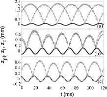
For , complicated irregular hopping and tumbling motion is observed for most initial conditions. Here, we focus on the weak excitation regime . Clearly, for the dimer may remain on the plate. However, if the dimer is dropped onto the plate, three main modes of persistent motion can be observed depending on initial conditions. The vertical coordinates of the tips of the dimer tips in the laboratory frame of reference are plotted in Fig. 2. In the highest energy mode, the tips hit the plate out of phase at every other period of oscillation [see Fig. 2(a)]. We call this motion the flutter (F) mode. In the next lower energy mode, both tips collide with the plate once every cycle [see Fig. 2(b)]. We call this the jump (J) mode. In this mode the dimer does not have significant angular momentum and resembles the first excited mode of a single particle bouncing on an oscillated plate. The lowest energy mode is shown in Fig. 2(c). As can be noted from the figure, one of the ends of the dimer hits the plate once every cycle while the other appears to stay on the plate throughout the cycle. In addition to the non-trivial vertical motion, a persistent horizontal drift is observed and therefore we call it the drift (D) mode movie . Although the excitation of a particular mode depends sensitively on the initial conditions, the drift mode can be excited easily by lifting one end by a fraction of the sphere diameter and releasing it while keeping the other end on the plate.
To test that sidewalls have negligible effect on the dynamics, we also performed experiments using a container with a shallow 1mm deep U-shaped groove with crossectional curvature which is at least four times that of the spheres in the dimer. The curvature focuses the dynamics to a vertical plane without dimer-sidewall collisions. Similar results were observed. However, higher quality position data is obtained with the container with sidewalls, and used to report details of dynamics.
We can characterize the different modes by the total mechanical energies of the vibrating dimer. As a simple measure of such energy we take the sum of maximum elevations of both spheres above the plate. Ignoring inelasticity and horizontal translation yields the following estimates of energies per unit mass of drift, jump, and flutter modes for . Therefore the ratio of the energy for the drift, jump and flutter mode is approximately 1:2:8, which is consistent with observations.
In the remainder of the paper we focus on the D-mode, since it exhibits the most non-trivial dynamics. The horizontal coordinate of the left tip of the dimer “resting” on the plate is plotted as shown in Fig. 3(a) versus time for dimer with (solid line), and (dashed line) at Hz. In Fig. 3(a), the net motion of the dimer is directed towards its bouncing end. In the following, this direction is called forward or positive.
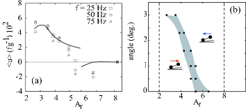
We measured the horizontal drift speed of dimers with various between 2 and 10 at three different frequencies of vibration [see Fig. 4(a)]. The speed is determined by measuring the time taken by the dimer to move over a 55 mm horizontal distance. For , the D-mode becomes unstable. The drift speed is maximal for an aspect ratio of approximately 3.5, and then observed to decrease as is increased. It can be also noted that dimer moves in the backward direction at large .
 |
We also varied the driving parameters to check their influence on the dimer dynamics. We found that the drift speed of the D-mode is inversely proportional to [see Fig. 4(a)]. However, for fixed , the drift speed is almost independent of over a broad range. For example, for and Hz, the measured speed was approximately constant over a range of between 0.5 and 1.1. For smaller , the D-mode spontaneously collapses to rest, and for higher , the D-mode is unstable with respect to the transition to the higher energy J and F-modes, and their combinations.
We checked that the drift motion is not due to any residual tilt in the plate by testing that the speed is the same when the dimer moves in either direction. Furthermore, when the oscillated plate was deliberately tilted, uphill motion was observed depending on over a range of angles [see Fig. 4(b)]. (These experiments where performed with the U-shaped bottom plate which has no sidewalls.) Thus the driving mechanism in the drift mode is robust enough to overcome gravity.
Detailed examination of each tip reveals that the horizontal drift occurs due to the asymmetric slip of the low-energy left sphere “resting” on the plate (see Fig. 3). Specifically, the horizontal velocity of the left tip is plotted in Fig. 3(b). For small , the positive slip which begins immediately after the right sphere collides with the plate, gradually slows down and is succeeded by a slower negative slip during the phase when the right end of the dimer approaches the plate, after which the process repeats. For large , the positive slip is much smaller or absent, and the drift is dominated by negative slip.
Although it appears from Fig. 2(c) that the left sphere is simply rolling on the plate, in fact it performs a sequence of small jumps immediately after the right sphere collides with the plate. We confirmed both the loss of contact after the collision during the small jumps as well as the fact that the left sphere is in contact with the plate for a large fraction of the cycle by measuring the electric resistance between the spheres and the plate.
Our theoretical description of the dimer dynamics is based on a detailed analysis of frictional contacts between the dimer and the plate. Frictional inelastic oblique collision between asymmetric bodies has been a subject of many studies in contact mechanics where various regimes of isolated contacts have been identified (see e.g. stronge90 ). Depending on the geometry and the incident velocity of the body one can distinguish three qualitatively different regimes: continuous slide, slip-stick, or slip-reversal (see also Ref. volfson04 for the case of thin rods). In addition to these regimes, the dimer in the D-mode experiences an even greater variety of contacts with the plate, including three types of double collisions (slide, slip-stick, and slip reversal) when two spheres touch the plate simultaneously, and two regimes of rolling (with or without sliding).
The dynamics of the dimer is governed by the Newton equations written for the center of mass (CM) velocity and the angular velocity
| (1) |
where are the dimer mass and moment of inertia, is the contact force, and is radius-vector from CM to a contact point (CP) [see also Fig. 1]. The sum over indicates that either left or right or both spherical ends can be in contact with the plate during collisions. The CP velocity components in the plate frame of reference are given by , where is the plate velocity. In a sliding contact, , where is the friction coefficient and , and in the sticking phases, is found from the no-slip condition . Transitions from stick to slip occur when with the static friction coefficient . Although the gravitational force can be neglected during collisions, it must be taken into consideration during flight and rolling.
For isolated collisions, we integrate Eqs. (1) with initial conditions and the kinematic condition (where indices correspond to before and after collision, and is the kinematic restitution coefficient), to obtain after-collision CM velocities . Note that the dynamic and static friction coefficients for the rolling phase in general can differ significantly from those for the short collisions israelachvili and we use separate notations and for the latter coefficients. A detailed description of all contact types is rather cumbersome and will be presented elsewhere dorbolo04b (see also Supplementary material).
We combined the conditions for the occurrence of the various kinds of collisions and the forces acting on the dimer into an event-driven algorithm. We used this algorithm to elucidate the origin of the observed regimes of dimer motion. In D-mode, the left tip rolls on the plate with negative slippage as the right tip approaches the plate (see Fig. 5). At time , the right tip collides with the plate with an incident contact velocity . In the first phase of collision, negative slippage slows down due to the frictional force . For large enough friction, at a certain time during collision, the negative slip stops (). If formally , the dimer leaves the plate before the negative slip stops, and so the collision would be of a continuous slide type. Continuous negative slide cannot persist in the stationary regime, because this would yield cumulative positive horizontal impulse transfer from the plate to the dimer over the period of vibration and hence an accelerated motion. For , there can be two possible scenarios for the second phase of the double collision. For large enough aspect ratios, , (where ,) the CP sticks at , i.e. . For , the slip reverses direction, in which case it can be shown that is given by

.
For small , becomes positive after the double collision in agreement with experiment [cf. Fig. 5(b) and Fig. 3(b)]. This “kick” during the two point collision is the main source of the positive drift momentum. Simultaneously, the right tip acquires a finite vertical velocity which equals . The left tip also acquires a small positive vertical velocity , resulting in the dimer being lifted off the plate. Following the lift-off, the left end makes a sequence of collisions with the plate which result in a decaying sequence of small flights. This sequence converges through inelastic collapse at time , after which the left tip of the dimer stays on the plate. Meanwhile the right end of the dimer is still in the air, and the rolling mode with slippage commences and continues until the right tip finally collides with the plate, after which the process repeats.
For large , the double collision is of the slip-stick type, so that , and the mean slip velocity is negative [Fig. 5(c)]. While this picture qualitatively agrees with the experimental findings [compare Fig. 5(b),(c) with Fig. 3(b)], in order to match the mean drift velocity quantitatively [see Fig. 4(a)], we had to choose for short-term collisions which were half of those for the rolling phase. While we do not have a good explanation for the smaller values, it is well known israelachvili that the friction properties depend strongly on the age of the contact and therefore can differ between short-time collisions and relatively long rolling contacts. As seen in Fig. 4(a), even with this fitting of friction parameters, there is a significant deviation between theory and observations for large aspect ratios. In particular, experiments do not show a discontinuous transition from forward to reverse drift at a certain . We believe that this discrepancy can be explained by the sensitivity of the double collision to small variations in frictional properties of the plate at large .
In conclusion, we investigated the dynamics of a dimer bouncing on an oscillated plate with the special focus on the first excited D-mode in which the dimer travels in one of the two directions selected via a symmetry breaking. In typical fluctuation-driven transport systems, the direction of transport is selected by the local asymmetry of microscopic potential derenyi98 . In contrast, our bouncing dimer presents a novel phenomenon of ratchet motion in a system without an imposed asymmetric potential olafsen . Our theoretical analysis reveals that the D-mode is in fact a concatenation of multiple collisions which include individual, double, and rolling contacts. Horizontal transport is forced by the Coulomb friction during collisions and rolling phases. Because our preliminary experiments show that the drift mode survives collisions, one can anticipate that a collection of dimers, while initially exhibting random motion, will align mutually due to excluded volume interactions amplified by inelastic collisions. We expect that this alignment would give rise to a global convection similar to vortices observed with rods blair03 ; aranson03 .
SD thanks FNRS for financial support. This work was supported by NSF grant # DMR-9983659 (Clark) and the U.S. DOE grant DE-FG02-04ER46135 (UCSD).
References
- (1) F. X. Villarruel, B. E. Lauderdale, D. M. Mueth, and H. M. Jaeger, Phys. Rev. E 61, 6914 (2000); K. Stokely, A. Diacou, and S.V. Franklin, Phys. Rev. E 67, 051302 (2003).
- (2) V. Frette, et al., Nature (London) 379, 49 (1996).
- (3) D. L. Blair, T. Neicu, and A. Kudrolli, Phys. Rev. E 67, 031303 (2003).
- (4) I. S. Aranson and L. S. Tsimring, Phys. Rev. E 67, 021305 (2003).
- (5) D. Volfson, A. Kudrolli, and L. S. Tsimring, Phys. Rev. E 70, 051312 (2004).
- (6) I. Derényi, P. Tegzes, and T. Viscek, Chaos, 8, 657 (1998); Z. Farkas, P. Tegzes, A. Vukics, and T. Vicsek, Phys. Rev. E 60, 7022 (1999); J. F. Wambaugh, C. Reichhardt, and C. J. Olson, Phys. Rev. E 65, 031308 (2002).
- (7) See, e.g., N. B. Tufillaro, T. Abbot, and J. Reilly, An Experimental Approach to Nonlinear Dynamics and Chaos (Addison-Wesley, New York, 1992).
- (8) See movies of the modes in the supplementary material (also at: http://physics.clarku.edu/akudrolli/dimer/).
- (9) We call the tip the point on the sphere surface directly underneath its center.
- (10) D. Volfson, et al., to be published.
- (11) W. J. Stronge, Proc. R. Soc. London A, 431, 169 (1990); Y. Hurmuzlu, ASME J. Appl. Mech., 65, 952 (1998).
- (12) J. N. Israelachvili, Intermolecular and Surface Forces, Academic Press: London, 2nd ed. (1991).
- (13) In a recent preprint cond-mat/0306646, J. Atwell and J. S. Olafsen reported anisotropy of velocity fluctuations of loosely connected pairs of grains on a vibrated plate which may be caused by similar ratchet mechanism.