Resonant backward scattering of light by a two-side-open subwavelength metallic slit
Abstract
The backward scattering of TM-polarized light by a two-side-open subwavelength slit in a metal film is analyzed. We show that the reflection coefficient versus wavelength possesses a Fabry-Perot-like dependence that is similar to the anomalous behavior of transmission reported in the study [Y. Takakura, Phys. Rev. Lett. 86, 5601 (2001)]. The open slit totally reflects the light at the near-to-resonance wavelengths. In addition, we show that the interference of incident and resonantly backward-scattered light produces in the near-field diffraction zone a spatially localized wave whose intensity is 10-103 times greater than the incident wave, but one order of magnitude smaller than the intra-cavity intensity. The amplitude and phase of the resonant wave at the slit entrance and exit are different from that of a Fabry-Perot cavity.
pacs:
78.66.Bz; 42.25.Fx; 07.79.Fc; 42.79.AgI Introduction
The most impressive features of light scattering by subwavelength metallic nanostructures are resonant enhancement and localization of the light by excitation of electron waves in the metal (for example, see refs. Neer ; Harr ; Betz1 ; Ebbe ; Hess ; Nev ; Nev1 ; Sarr1 ; Cscher ; Port ; Trea ; Asti ; Pop ; Bozs ; Taka ; Yang ; Hibb ; Gar3 ; Cao ; Barb ; Dykh ; Stee ; Shi ; Scho ; Naha ; Bouh ; Kuk2 ; Gar1 ; Lind ; Xie ; Decha ; Bori ; Fan ; Zay ; Li ; Lab ; Ben ; Monz ; Vigo ). In the last few years, a great number of studies have been devoted to the nanostructures in metal films, namely a single aperture, a grating of apertures and an aperture surrounded by grooves. Since the recent paper of Ebbesen and colleaguesEbbe on the resonantly enhanced transmission of light observed for a 2D array of subwavelength holes in metal films, the resonant phenomenon is intensively discussed in the literature.Ebbe ; Hess ; Nev ; Nev1 ; Sarr1 ; Cscher ; Port ; Trea ; Asti ; Li ; Pop ; Bozs ; Taka ; Yang ; Hibb ; Gar3 ; Cao ; Barb ; Dykh ; Stee ; Shi ; Scho ; Naha ; Bouh ; Kuk2 ; Gar1 ; Lind ; Xie ; Decha ; Bori ; Fan ; Zay ; Monz ; Vigo Such a kind of light scattering is usually called a Wood’s anomaly. In the early researches, Hessel and Oliner showed that the resonances come from coupling between nonhomogeneous diffraction orders and eigenmodes of the grating.Hess Neviere and co-workers discovered two other possible origins of the resonances.Nev ; Nev1 One appears when the surface plasmons of a metallic grating are excited. The other occurs when a metallic grating is covered by a dielectric layer, and corresponds to guided modes resonances in the dielectric film. The role of resonant Wood’s anomalies and Fano’s profiles in the resonant transmission were explained in the study.Sarr1
The phenomena involved in propagation through hole arrays are different from those connected with slit arrays. In a slit waveguide there is always a propagating mode inside the channel, while in a hole waveguide all modes are evanescent for hole diameters smaller than approximately a wavelength. In the case of slit apertures in a thick metal film, the transmission exhibits enhancement due to a pure geometrical reason, the resonant excitation of propagating modes inside the slit waveguide.Port ; Hibb ; Taka ; Asti ; Cao At the resonant wavelengths, the transmitted field increases via the strong coupling of an incident wave with the waveguide modes giving a Fabry-Perot-like behavior.Asti ; Taka ; Yang ; Kuk2 In the case of films, whose thickness are too small to support the intra-cavity resonance, the extraordinary transmission can be caused by another mechanism, the generation of resonant surface plasmon polaritons and coupling of them into radiation.Ebbe ; Port ; Hibb ; Gar1 ; Cscher Both physical mechanisms play important roles in the extraordinary transmission through arrays of two-side-open slits (transmission gratings) and the resonant reflection by arrays of one-side-open slits (reflection gratings). A model of trapped (waveguide) modes has been recently used to show that an array of two-side-open slits can operate like a reflection grating totally reflecting TE-polarized light.Bori The surface plasmons and Rayleigh anomalies were involved in explanation of reflective properties of such a kind of gratings.Stee
The studies Taka ; Yang ; Gar3 ; Kuk2 have pointed out that the origin of anomalous scattering of light by a grating of slits (holes) can be better understood by clarifying the transmission and reflection properties of a single subwavelength slit. Along this direction, it was already demonstrated that the intensity of TM-polarized light resonantly transmitted through a single slit can be 10-103 times higher than the incident waveNeer ; Harr ; Betz1 ; Kuk2 and that the transmission coefficient versus wavelength possesses a Fabry-Perot-like behaviorTaka ; Yang ; Kuk2 . Unfortunately, the reflection properties of the slit have received no attention in the literature. The very recent studyBori only concerned the problem by regarding the total reflection of TE-polarized light by a grating of two-side-open slits to properties of the independent slit emitters.
In this article, the backward scattering of light by a two-side-open subwavelength slit is analyzed. To compare properties of the light reflection with the extraordinary transmissionTaka ; Yang ; Kuk2 , we consider the scattering of TM-polarized light by a slit in a thick metallic film of perfect conductivity. From the latter metal property it follows that surface plasmons do not exist in the film. Such a metal can be described by the Drude model for which the plasmon frequency tends towards infinity. The traditional approach based on the Neerhoff and Mur solution of Maxwell’s equations is used in the computations.Neer ; Harr ; Betz1 The article is organized as follows. The theoretical background, numerical analysis and discussion are presented in Section II. The summary and conclusions are given in Section III. The brief description of the model is presented in the Appendix.
II Numerical analysis and discussion
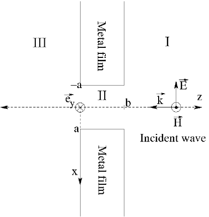
It is well known that when a light wave is scattered by a subwavelength metallic object, a significant part of the incident light can be scattered backward (reflected) whatever the object be reflecting or transparent. It was recently demonstrated that an array of two-side-open subwavelength metallic slits effectively reflects light waves at the appropriate resonant conditions.Stee ; Bori One may suppose that this is true also in the case of a single slit. In this section, we test whether a light wave can be resonantly reflected by a single two-side-open subwavelength metallic slit. To address this question, the energy flux in front of the slit is analyzed numerically for various regimes of the light scattering. In order to compare properties of the light reflection with that of the extraordinary (resonant) transmissionTaka ; Yang ; Kuk2 , we consider the zeroth-order scattering of a time-harmonic wave of TM-polarized light by a slit in a perfectly conducting thick metal film placed in vacuum (Fig. 1).
The energy flux in front of the slit is compared with the fluxes and inside the slit and behind the slit, respectively. The amplitude and phase of the light wave at the slit entrance and exit are compared with that of a Fabry-Perot cavity. The electric and magnetic fields of the light are computed by using the traditional approach based on the Neerhoff and Mur solution of Maxwell’s equations.Neer ; Harr ; Betz1 For more details of the model, see the Appendix.
According to the model, the electric and magnetic fields in front of the slit (region I), inside the slit (region II) and behind the slit (region III) are determined by the scalar fields , and , respectively. The scalar fields are found by solving the Neerhoff and Mur integral equations. The magnetic field of the wave is assumed to be time harmonic and constant in the direction: . In front of the slit, the field is decomposed into . The field represents the incident field, which is assumed to be a plane wave of unit amplitude; denotes the field that would be reflected if there were no slit in the film; describes the backward diffracted field due to the presence of the slit. The time averaged Poynting vector (energy flux) of the electromagnetic field is calculated (in CGS units) as . The reflection coefficient is given by the normalized flux integrated over the slit width at the slit entrance (), where is the component of the backward scattered flux, and is the incident flux along the direction. The flux is produced by the interference of the backward scattered fields and . The transmission coefficient is determined by the normalized flux integrated over the slit width at the slit exit (), where the flux -component is produced by the forward scattered (transmitted) field . Notice that the definitions of the reflection and transmission coefficients are equivalent to the more convenient ones defined as the integrated reflected or transmitted flux divided by the integrated incident flux. In the following analysis, the reflection and transmission coefficients are compared to the fluxes and obtained by integrating the normalized fluxes and , respectively.
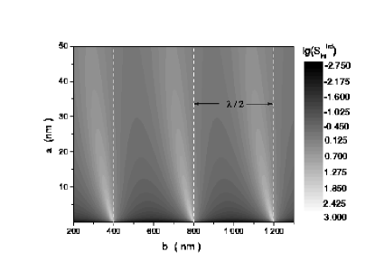
We analyzed the backward scattering of light for a wide range of scattering conditions determined by values of the wavelength , slit width and film thickness . As an example, the reflection coefficient as a function of the film thickness computed for the wavelength nm and the slit width nm is shown in Fig. 2.

(a)
(b)
The transmission coefficient and the integrated fluxes and are presented in the figure for the comparison. We note the reflection resonances of periodicity with the maxima . In agreement with the previous resultsTaka ; Yang ; Kuk2 , one can see also the transmission resonances having the same period, and the peak heights () at the resonances. It is worth to note the correlation between the positions of maxima and minima in the reflection and transmission. The resonance positions for the total reflection are somewhat left-shifted with respect to the transmission resonances. The maxima of the transmission coefficient correspond to reflection minima. In Fig. 2, one can observe also many satellite peaks in reflection. For one broad minimum, it appears a local reflection maximum, which is characterized by a weak amplitude. The local maxima appear before 400, 800, and 1200 nm. The positions of the local maxima approximately correspond to the maxima. To clarify a role of the fields , , and in the resonant backward scattering, we compared the integrated flux with the fluxes and . One can see from Fig. 2 that the flux produced in front of the slit by the interference of the incident field and the backward scattered fields and is practically undistinguishable from that generated by the backward diffracted field and forward scattered (transmitted) field . The integrated flux as a function of the slit half-width and film thickness is shown in Fig. 2. We notice that the widths and shifts of the resonances increase with increasing the value . Analysis of Fig. 2 indicates that the difference between the integrated fluxes and () appears due to the interference of the backward diffracted field and the reflected field .
The dispersion of the reflection coefficient for the slit width nm and the screen thickness nm is shown in Fig. 3.

(a)
(b)
The integrated fluxes , and versus the wavelength are shown in the figure for the comparison. A very interesting behavior of the dispersion is that the coefficient versus the wavelength possesses a Fabry-Perot-like dependence that is similar to the anomalous behavior of transmission reported in the studiesAsti ; Taka ; Yang ; Gar3 ; Kuk2 . In agreement with the studiesNeer ; Harr ; Betz1 ; Kuk2 , the height of the first (maximum) transmission peak is given by . The wavelengths corresponding to the resonant peaks () are in accordance with the resultsTaka . The high peak amplitudes (enhancement), however, are different from the low magnitudes (attenuation) predicted in the studyTaka , but compare well with the experimental and theoretical resultsNeer ; Harr ; Betz1 ; Kuk2 ; Yang . The difference is caused by the manner in which the Maxwell equations are solved. The studyTaka uses a simplified approach based on the matching the cavity modes expansion of the light wave inside the slit with the plain waves expansion above and below the slit using two boundary conditions, at and . Conversely, the Neerhoff and Mur method performs the matching with five boundary conditions, at , , , , and . In contrast to the sharp Lorentzian-like transmission peaks, the slit forms very wide Fano-type reflection bands (see, Fig. 3). For one broad minimum in reflection, it appears also a local reflection maximum, which is characterized by weak amplitude. At the near-to-resonance wavelengths of the transmission, the open aperture totally reflects the light. It is worth to note the correlation between the wavelengths for maxima and minima in the reflection , transmission , and the flux (Table 1).
| (nm) of | |||
| 276 | 248 | 237 | |
| 426 | 377 | 255 | |
| 882 | 773 | 356 | |
| 389 | |||
| 714 | |||
| 802 | |||
| (nm) of | |||
| 260 | 226 | 253 | |
| 396 | 315 | 388 | |
| 812 | 542 | 802 |
The resonance wavelengths for the main reflection maxima are red-shifted with respect to the transmission resonances. The wavelengths of both the transmission and reflection (main and little) resonances are red-shifted with respect to the Fabry-Perot wavelengths nm, nm, (, ). To understand the physical mechanism of the resonant backward scattering, we also compared the integrated flux with the fluxes and . As can be seen from Fig. 3, the integrated fluxes , and are practically undistinguishable also in the -domain (for the -domain, see Fig. 2). The difference between the integrated fluxes and () is caused by the interference of the backward diffracted field and the reflected field in the energy flux . The wavelengths of the little maxima of the reflection correspond approximately to the high maxima . Therefore, the little maxima can be attributed to the interference of the reflected field with the dominant diffracted field . The red shifts and the asymmetrical shapes of the reflection bands can be explained by a Fano analysisSarr1 of the scattering problem by distinguishing resonant and non-resonant interfering contributions to the reflection process. The resonant contribution is given by the field and the non-resonant one is attributed to the field . Other interesting interpretations of the shifts of resonant wavelengths in the transmission spectra from the values can be found in the studiesAsti ; Taka ; Yang ; Kuk2 ; Bori ; Trea . It should be mentioned that the asymmetrical behavior of reflection was observed also in the case of a Fabry-Perot resonatorMonz ; Vigo . The conditions to achieve such an asymmetry are rested on the existence of dissipative loss in the resonator. There is no explicit loss in the present problem, but the dissipative loss can be substituted by radiative loss due to the diffraction by the slit.
After the analysis of Fig. 2, it is not surprising that the maxima of the transmission are accompanied by the minima of the reflection also in the -domain (see, Fig. 3). It should be noted in this connection that such a behavior of and is similar to that observed in the case of excitation of the surface plasmons in an array of slit in a thin metal film.Stee In the studyStee , the minima in reflection spectra corresponding to the maxima in the transmission spectra were attributed to the redistribution of the energy of diffracted evanescent order into the propagating order. In the case of a thick film, we explain such a behavior by another physical mechanism, the interference of the backward diffracted field and the reflected field . It can be noted that the correlation of positions of reflection minima and transmission maxima (see, Figs. 2 and 3) are consistent with that predicted by the studyBori for TE-polarized light scattered by a grating of two-side-open slits in a thick metal film. However, the values of and are in contrast to the relation given in the studyBori . The difference can be explained by the fact that we examined light scattering by an infinite screen using local definitions of and , while the studyBori analyzed the global reflection and transmission by a grating of finite size.
(a)
(b)
(a)
(b)
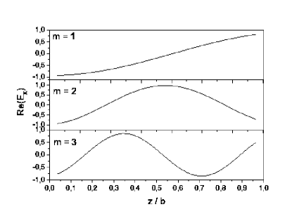
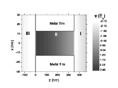
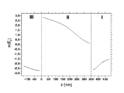
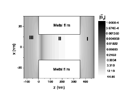
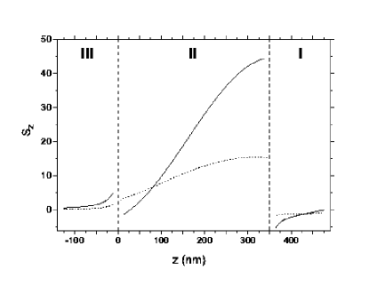
The dispersions , and shown in Fig. 3 indicate the wave-cavity interaction behavior, which is similar to that in the case of a Fabry-Perot resonator. The fluxes , and exhibit the Fabry-Perot-like maxima around the resonance wavelengths . In order to understand the connection between the Fabry-Perot-like resonances and the total reflection, we computed the amplitude and phase distributions of the light wave at the resonant and near-resonant wavelengths inside and outside the slit cavity (see, Figs. 3, 4 and 5). At the resonance wavelengths, the intra-slit fields possess maximum amplitudes with Fabry-Perot-like spatial distributions (Fig. 3). However, in contrast to the Fabry-Perot-like modal distributions, the resonant configurations are characterized by antinodes of the electric field at each open aperture of the slit. Such a behavior is in agreement with the resultsAsti ; Lind ; Xie . It is interesting that at the slit entrance, the amplitudes of the resonant field configuration possesses the Fabry-Perot-like phase shift on the value of (Fig. 4). The integrated fluxes , and , at the first resonant wavelength , exhibit enhancement by a factor with respect to the incident wave (Fig. 3). For the comparison, the normalized resonant fluxes and in the near-field zone () are about 5 times greater than the incident wave (see, Fig. 5). It should be stressed that the resonantly enhanced intra-cavity intensity is about 10 times higher than the resonant fluxes and localized in the near field zone in front of the slit and behind the slit, respectively (Fig. 5). The interference of the incident wave and the backward scattered fields and , at the resonant wavelengths , produces in the near-field diffraction zone a strongly localized wave whose normalized flux is 10-103 times greater than the incident wave, but about one order of magnitude smaller than the resonant intra-cavity intensity.
In our model we considered an incident wave with TM polarization. According to the theory of waveguides, the vectorial wave equations for this polarization can be reduced to one scalar equation describing the magnetic field of TM modes. The electric component of these modes is found using the field and Maxwell’s equations. The TM scalar equation for the component is decoupled from the similar scalar equation describing the field of TE (transverse electric) modes. Hence, the formalism works analogously for TE polarization exchanging the and fields.
III Summary and conclusion
In the present paper, the backward scattering of TM-polarized light by a two-side-open subwavelength slit in a metal film has been analyzed. We predict that the reflection coefficient versus wavelength possesses a Fabry-Perot-like dependence that is similar to the anomalous behavior of transmission. The open slit totally reflects the light at the near-to-resonance wavelengths. The resonance wavelengths for the total reflection are somewhat red-shifted with respect to the transmission resonances. The wavelengths of both the reflection and transmission resonances are red-shifted with respect to the Fabry-Perot wavelengths. The sharp resonant maxima of transmission are accompanied by the wide minima of the reflection. In addition, we showed that the interference of incident and resonantly backward-scattered light produces in the near-field diffraction zone a strongly localized wave whose intensity is greater than the incident wave by a factor 10-103 and about one order of magnitude smaller than the intra-cavity intensity. The correlation between the amplitude and phase distributions of light waves inside and outside the slit was also investigated. The slit cavity was compared with a Fabry-Perot resonator. We showed that the amplitude and phase of the resonant wave at the slit entrance and exit are different from that of a Fabry-Perot cavity. The physical mechanism responsible for the total reflection is the interference of the backward diffracted resonant field and the reflected non-resonant field in the energy flux at the near-to-resonance wavelengths (Fano-type effect). The wavelength-selective total reflection of light by two-side-open metal slits may find application in many kinds of sensors and actuators. The (10-103)-times and (-)-times enhancement of the light intensity in front of the slit and inside the slit can be used in reflective nanooptics and in intra-cavity spectroscopy of single atoms. We believe that the presented results gain insight into the physics of resonant scattering of light by subwavelength nano-slits in metal films.
Acknowledgements.
The authors appreciate the valuable comments and suggestions of the anonymous referees. This study was supported by the Fifth Framework of the European Commission (Financial support from the EC for shared-cost RTD actions: research and technological development projects, demonstration projects and combined projects. Contract NG6RD-CT-2001-00602) and in part by the Hungarian Scientific Research Foundation (OTKA, Contracts T046811 and M045644) and the Hungarian R&D Office (KPI, Contract GVOP-3.2.1.-2004-04-0166/3.0).Appendix
We briefly describe the Neerhoff and Mur modelNeer ; Betz1 of the scattering of a plane continuous wave by a subwavelength slit of width in a perfectly conducting metal screen of thickness . The slit is illuminated by a normally incident plane wave under TM polarization (magnetic-field vector parallel to the slit), as shown in Fig. 1. The magnetic field of the wave is assumed to be time harmonic and constant in the direction:
| (1) |
The electric field of the wave is found from the scalar field using Maxwell’s equations. The restrictions in Eq. (1) reduce the diffraction problem to one involving a single scalar field in two dimensions. The field is represented by (=1,2,3 in region I, II and III, respectively), and satisfies the Helmholtz equation: where . In region I, the field is decomposed into three components:
| (2) |
each of which satisfies the Helmholtz equation. represents the incident field:
| (3) |
denotes the reflected field without a slit:
| (4) |
Finally, describes the diffracted field in region I due to the presence of the slit. With the above set of equations and standard boundary conditions for a perfectly conducting screen, a unique solution exists for the scattering problem. The solution is found by using the Green function formalism.
The magnetic fields in regions I, II, and III are given by
| (5) |
| (6) | |||||
| (7) | |||||
where , ; ; is the Hankel function; , ; . The coefficients are found by solving numerically four coupled integral equations. For more details on the model and the numerical solution of the Neerhoff and Mur coupled integral equations, see the referencesNeer ; Betz1 .
References
- (1) F. L. Neerhoff and G. Mur, Appl. Sci. Res. 28, 73 (1973).
- (2) R.F. Harrington and D.T. Auckland, IEEE Trans. Antennas Propag AP28, 616 (1980).
- (3) E. Betzig, A. Harootunian, A. Lewis, and M. Isaacson, Appl. Opt. 25, 1890 (1986).
- (4) T.W. Ebbesen, H.J. Lezec, H.F. Ghaemi, T. Thio, and P.A. Wolff, Nature (London) 391, 667 (1998).
- (5) A. Hessel and A.A. Oliner, Appl. Opt. 4, 1275 (1965).
- (6) M. Nevière, D. Maystre, and P. Vincent, J. Opt. 8, 231 (1977).
- (7) D. Maystre and M. Nevière, J. Opt. 8, 165 (1977).
- (8) M. Sarrazin, J.P. Vigneron, and J.M. Vigoureux, Phys. Rev. B 67, 085415 (2003).
- (9) J. A. Porto, F.J. García-Vidal, and J.B. Pendry, Phys. Rev. Lett. 83, 2845 (1999).
- (10) S. Astilean, Ph. Lalanne, and M. Palamaru, Opt. Commun. 175, 265 (2000).
- (11) A.P. Hibbins, J.R. Sambles and C.R. Lawrence, Appl. Phys. Lett. 81, 4661 (2002).
- (12) Q. Cao and P. Lalanne, Phys. Rev. Lett. 88, 057403 (2002).
- (13) Y. Takakura, Phys. Rev. Lett. 86, 5601 (2001).
- (14) F.Z. Yang and J.R. Sambles, Phys. Rev. Lett. 89, 063901 (2002).
- (15) S.V. Kukhlevsky, M. Mechler, L. Csapo, K. Janssens, and O. Samek, Phys. Rev. B 70, 195428 (2004).
- (16) F.J. García-Vidal, H.J. Lezec, T.W. Ebbesen, and L. Martín-Moreno, Phys. Rev. Lett. 90, 231901 (2003).
- (17) A.G. Borisov, F.G. Garcia de Abajo, and S.V. Shabanov, Phys. Rev. B 71, 075408 (2005).
- (18) J.M. Steele, C.E. Moran, A. Lee, C.M. Aguirre, and N.J. Halas, Phys. Rev. B 68, 205103 (2003).
- (19) F.J. García-Vidal and L. Martín-Moreno, Phys. Rev. B 66, 155412 (2002).
- (20) J. Lindberg, K. Lindfors, T. Setala, M. Kaivola, and A.T. Friberg, Opt. Express 12, 623 (2004).
- (21) Y. Xie, A.R. Zakharian, J.V. Moloney, and M. Mansuripur, Opt. Express 12, 6106 (2004).
- (22) U. Schröter and D. Heitmann, Phys. Rev. B 58, 15419 (1998).
- (23) M.M.J. Treacy, Phys. Rev. Lett. 75, 606 (1999).
- (24) J.M. Vigoureux and R. Giust, Opt. Commun. 186, 21 (2000).
- (25) J.J. Monzón, T. Yonte, and L.L. Sánchez-Soto, Opt. Commun. 218, 43 (2003)
- (26) E. Popov, M. Nevière, S. Enoch, and R. Reinisch, Phys. Rev. B 62, 16100 (2000).
- (27) S.I. Bozhevolnyi, J. Erland, K. Leosson, P.M.W. Skovgaard, and J.M. Hvam, Phys. Rev. Lett. 86, 3008 (2001).
- (28) A. Barbara, P. Quemerais, E. Bustarret, and T. Lopez-Rios, Phys. Rev. B 66, 161403 (2002).
- (29) A.M. Dykhne, A.K. Sarychev, and V.M. Shalaev, Phys. Rev. B 67, 195402 (2003).
- (30) X.L. Shi, L. Hesselink, and R.L. Thornton, Opt. Lett. 28, 1320 (2003).
- (31) H.F. Schouten, T.D. Visser, D. Lenstra, and H. Blok, Phys. Rev. E 67, 036608 (2003).
- (32) A. Nahata, R.A. Linke, T. Ishi, and K. Ohashi, Opt. Lett. 28, 423 (2003).
- (33) A. Bouhelier, M. Beversluis, A. Hartschuh, and L. Novotny, Phys. Rev. Lett. 90, 013903 (2003).
- (34) K.R. Li, M.I. Stockman, and D.J. Bergman, Phys. Rev. Lett. 91, 227402 (2003).
- (35) A. Dechant and A.Y. Elezzabi, Appl. Phys. Lett. 84, 4678 (2004).
- (36) W.J. Fan, S. Zhang, B. Minhas, K.J. Malloy, and S.R.J. Brueck, Phys. Rev. Lett. 94, 033902 (2005).
- (37) A.V. Zayats, I.I. Smolyaninov, and A.A Maradudin, Phys. Rep. 408, 131 (2005).
- (38) M. Labardi, M. Zavelani-Rossi, D. Polli, G. Cerullo, M. Allegrini, S. De Silvestri, and O. Svelto, Appl. Phys. Lett. 86, 031105 (2005).
- (39) Y. Ben-Aryeh, International J. Quantum Information 3, 111 (2005).