The RFOFO Ionization Cooling Ring for Muons
Abstract
Practical ionization cooling rings could lead to lower cost or improved performance in neutrino factory or muon collider designs. The ring modeled here uses realistic three-dimensional fields. The performance of the ring compares favorably with the linear cooling channel used in the second US Neutrino Factory Study. The normalized 6D emittance of an ideal ring is decreased by a factor of approximately 240, compared with a factor of only 15 for the linear channel. We also examine such real-world effects as windows on the absorbers and rf cavities and leaving empty lattice cells for injection and extraction. For realistic conditions the ring decreases the normalized 6D emittance by a factor of 49.
I Introduction
Designs for neutrino factories M. M. Alsharo´a et al. (2003) and muon colliders C.M. Ankenbrandt, et al. (1999) use ionization cooling to reduce the emittance of the muon beam prior to acceleration. Ionization cooling is currently the only feasible option for cooling the beam within the muon lifetime If muons alternately pass through a material absorber, and are then re-accelerated, and if there is sufficient focusing at the absorber, then the transverse phase space is reduced, i.e. the muons are cooled in the transverse dimension.
A consequence of the transverse cooling is an increase of the longitudinal phase space caused by the unfavorable slope of the dE/dx curve for momenta below the ionization minimum and by energy straggling in the material. The momentum spread can be reduced if dispersion is introduced and a wedge-shaped absorber is placed such that high momentum particles pass through more material than low momentum particles. However, when this procedure is carried out the beam width is increased. The process is thus primarily an exchange of emittance between the longitudinal and transverse dimensions. Moreover, when combined with transverse cooling in the material, all three dimensions can be cooled.
Early muon collider studies had assumed that transverse cooling and emittance exchange would be done in alternating stages. The transverse cooling used straight channels with rf and absorbers, while the emittance exchange employed bent solenoids and wedges. A serious problem with this approach was found to be the necessary matching between the two types of lattices. However, there has been considerable progress over the past few years in achieving 6D ionization cooling in cooling rings R.B. Palmer (2003). Ring coolers can overcome much of this matching problem by rapidly alternating the two functions.
The first ring cooler design V. Balbekov et al. (2001); V. Balbekov, A. van Ginneken (1998) was based on solenoid focusing. Alternate cells contained
-
•
transverse cooling in a long solenoid containing acceleration and a single hydrogen absorber
-
•
emittance exchange in a cell containing two bending magnets, two opposed solenoids, and a LiH wedge.
Matching between these cells has currently been achieved only with hard-edged magnetic fields. Each pair of cells is long enough that at least one half-integer betatron resonance is present within the momentum acceptance.
Later quadrupole-focused rings D.J. Summers et al. (2001); H. Kirk et al. (2003) took the process a step further, using a single cell type in which a wedge absorber cooled in both longitudinal and transverse phase space. These ideas eased the lattice design, but introduced the possibility for transverse emittance growth from energy straggling in the absorber, since it was now in a dispersive location. In addition, the weaker focusing in such quadrupole lattices limits the available amount of cooling and momentum acceptance. Current versions of this ring use edge-focused dipoles instead of quadrupoles, and high pressure gas instead of wedge absorbers. H. Kirk et al.
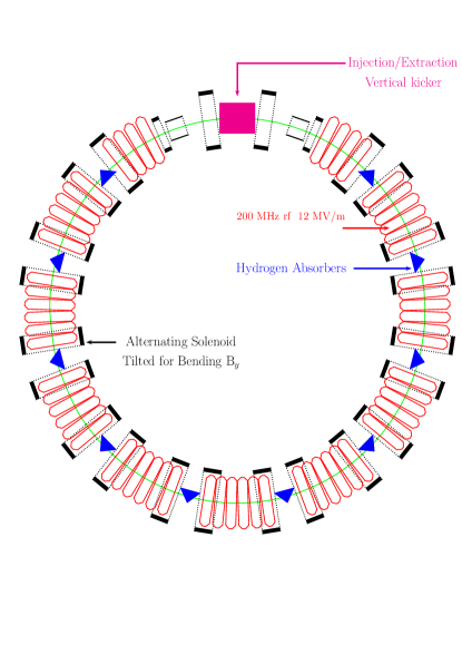
At present the most realistic modeling of a cooling ring has been done for the RFOFO cooling ring J.S. Berg, R.C. Fernow, R.B. Palmer (2002, 2003); R.C. Fernow et al. (2003); J.S. Berg et al. (2004). The FOFO part of the name refers to the focusing-drift-focusing nature of the solenoid lattice, in analogy to the FODO lattice for quadrupole channels. The prefix R designates a particular type of FOFO lattice where the magnetic cell has the same length as the geometric cell. As a result the axial field changes polarity in the middle of the cell. The ring discussed here follows the quadrupole design in the sense that it employs a single cell for doing both transverse cooling and emittance exchange. However, we use solenoidal focusing to obtain larger angular and momentum acceptances. The cell includes dispersion, acceleration, and energy loss in a single thick hydrogen wedge. The overall layout of the ring is shown in Fig. 1.
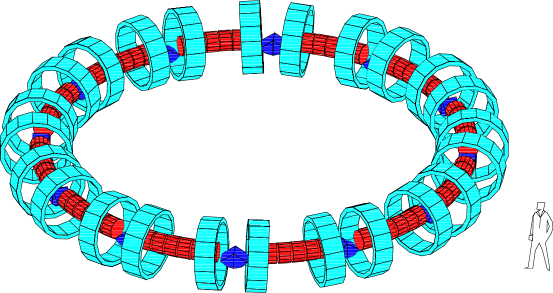
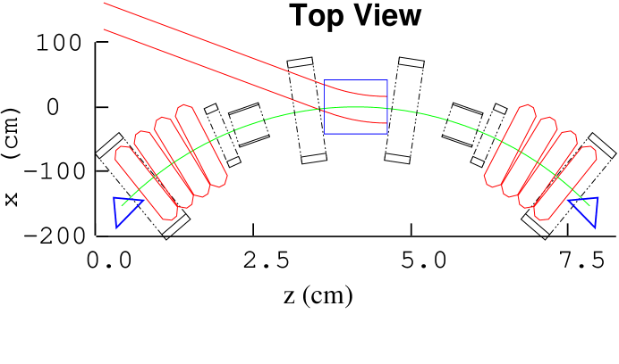
Two solenoids in each cell with opposite polarity provide transverse focusing. The solenoids are not equally spaced; those on either side of the absorbers are closer together in order to increase the focusing at the absorber. The vertical bending field is provided by alternately tipping the axes of the solenoids above and below the orbital mid-plane. The bending also provides the dispersion necessary for emittance exchange. A short cell length is used to obtain a small beta function with a reasonable value of the solenoid field strength. Wedge-shaped absorbers are placed in the beam path at the locations where the solenoidal field changes direction and the beta function is at a minimum. The lattice has dispersion at the rf cavities, which introduces synchro-betatron mixing and introduces some additional emittance growth.
However, we find that the disadvantage of having dispersion at the rf cavities is compensated by the greater acceptance from the use of a single repeating cell with no integer or half-integer betatron resonances in the momentum acceptance. In addition the longitudinal cooling provided by the wedge-shaped absorber minimizes losses from particles falling out of the rf bucket. Most of the lattice cell is filled with rf cavities that restore the energy lost in the absorbers, but empty cells are included where injection and extraction can take place.
II Modeling the Ring
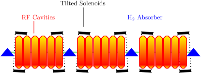
A more detailed layout of three cells of the ring is shown in Fig. 2 and a summary of ring properties is given in Table 1.
a)
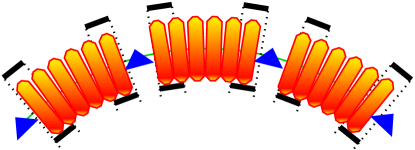
b)
| Circumference (m) | 33 |
| Total number of cells | 12 |
| Cells with rf cavities | 10 |
| Maximum axial field (T) | 2.77 |
| Coil tilt angle (degree) | 3 |
| Average vertical field (T) | 0.125 |
| Average momentum (MeV/c) | 220 |
| Minimum transverse beta function (cm) | 38 |
| Maximum dispersion function (cm) | 8 |
| Wedge opening angle (degree) | 100 |
| Wedge thickness on-axis (cm) | 28 |
| Cavities rf frequency (MHz) | 201.25 |
| Peak rf gradient (MV/m) | 12 |
| Cavities rf phase from 0-crossing (degree) | 25 |
The 33 m circumference ring is made up of 12 identical, 2.75 m long cells. The magnetic field is produced by solenoids of 50 cm in length, with an inner radius of 77 cm and an outer radius of 88 cm and a current density of The longitudinal field on-axis has an approximately sinusoidal dependence on position. The tilt angle of the solenoids was adjusted to provide a mean vertical bending field of 0.125 T. The centers of the solenoids are displaced radially outward from the 33 m reference circle by 10 cm to minimize the integrated on-axis radial field, which causes vertical beam deviations.
The RFOFO ring was modeled using three independent simulation codes. One private code was specifically written to examine this problem V. Balbekov (2002a, b, 2003).
The second code was ICOOL Fernow (1999), which has been widely used for neutrino factory and muon collider simulations. It includes a flexible system for specifying the problem geometry and magnetic fields. For this application the fields were either read in from an external file or calculated from on-axis multipoles. RF cavities were modeled as pillboxes, including the Bessel function radial dependence. Many of the energy loss, scattering and straggling routines in ICOOL are based on GEANT-3.21 GEANT Manual v.3.21 (1994).
The third code was the simulation software, MUC_GEANT R. Raja (2002), which is an application of GEANT-3.21, specially designed for muon cooling simulations. The Runge-Kutta routine was changed to include electric fields, so that rf acceleration would be simulated properly. The code is also data-driven, i.e. it allows the user to change the cooling channel parameters, such as geometry, rf frequency/gradient and physics processes, without recompiling. The magnetic field was read in from an external file. The rf was modeled as a purely axial field with no transverse variation.
The 3-dimensional magnetic field from the ring of tipped solenoids was calculated in three other independent codes by summing the fields from a set of current sheets V. Balbekov (2002b, 2003); R.C. Fernow, J.C. Gallardo (2002); S. Bracker (2003). There are some complexities in generating the fields for small rings which are much less important for straight cooling channels. The coils being used in this design are large-diameter, short, and carry high current; the maximum field is several Tesla. The ring is small, a little over 5 m in radius. We ignore for the moment the presence of any shielding iron. Then from every point in the active (muon-accessible) region of the ring, a particle is significantly affected by the field generated by all the coils, even the ones on the other side of the ring. Hence one must develop a single global field map, rather than assuming that a particle sees field components only from the closest coils.
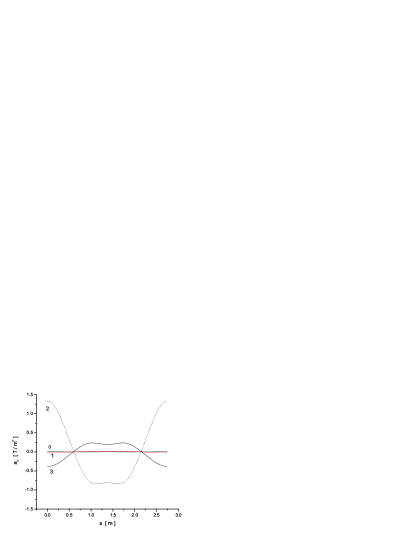
The field of a solenoidal current sheet can be written analytically in terms of elliptic integrals. The fields could also be generated from a set of coils using the Biot-Savart law. The resultant field components between the two methods agreed well and were shown to satisfy Maxwell’s equations to a high level of accuracy (approximately T/m). For GEANT a 3D field map was generated on a cartesian grid with 1 cm spacing in each dimension. For ICOOL we used a 3D field map in cylindrical coordinates, also with 1 cm grid spacing in each dimension. Because the fields were modeled from coils, all magnetic end field effects are automatically included in the simulations. The on-axis field components for one cell are shown in Fig. 3.


Once the magnetic field generator was working subsequent tracking could be done from the field calculated on a grid and saved to a map, or from multipoles R.C. Fernow, J.C. Gallardo (2003) of the field calculated around a reference circle. Figure 4 shows the calculated multipoles for one cell of the ring.
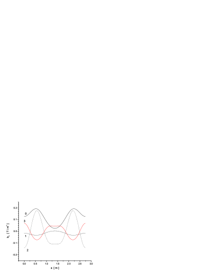
The on-axis transverse field has a rich spectrum of higher normal and skew multipoles.
Each lattice cell contains 6 rf cavity cells, each 33 cm long. The transit time factor for the cavity cells is 0.901. In ICOOL the rf cavities were modeled using cylindrical pillboxes running in the TM010 mode. The frequency is 201 MHz and the peak accelerating gradient is 12 MV/m. The cavity operates at a synchronous phase off the 0-crossing point. The cavities are located in dipole fields. Since we are accelerating muons, the cavities can be enclosed with metallic end windows in order to produce the maximum electric field on-axis for a given amount of rf power (maximum shunt impedance). The rf windows were stepped in thickness radially, in order to provide minimum thickness near the beam axis and still control the temperature increase due to rf heating.
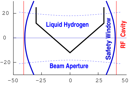
The liquid hydrogen wedge absorbers have a house shape, as shown in Fig. 5, and are located in dispersive regions in order to decrease the momentum spread in the beam.
The mean energy loss per cell in the absorber was 8.4 MeV. This energy loss was exactly compensated by the rf cavities. The energy gain per cell is
| (1) |
where is the number of rf cavities per cell, is the length of each cavity, is the peak rf gradient, is the transit factor and is the synchronous phase.
The simulated absorber windows were planar and located axially just in front of and behind the wedge itself. In reality the window shape will conform to the shape of the absorber and the effect on the beam of scattering in the window should be lessened. Because of the small bending field we use a wedge with maximum possible opening angle, which has zero thickness on one side. The wedge has a central thickness of 28 cm, a total wedge opening angle of and is rotated from the vertical to match the maximum of the dispersion. This combination of dispersion and wedge maximizes 6D emittance reduction.
III Lattice Functions and Beam Dynamics
For our initial studies of the basic lattice functions and beam dynamics we consider the ring with the magnetic field present, but no rf or absorbers. This enables us to simply study some of the basic features of the lattice, such as acceptances, beta function, closed orbits and dispersion functions.
III.1 Acceptance
We first examine the acceptance of the magnetic lattice as a function of momentum. A series of particles with small deviations from the closed orbit were tracked through one cell of the ring lattice. The eigenvalues were then extracted from the resulting linear transport matrix. The magnitude and phase of the largest eigenvalue are shown in Fig. 6.
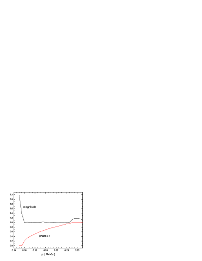
The magnitude is very close to 1 over the momentum band from 160 to 245 MeV/c. The ring has a very weak linear difference coupling resonance excited by the bend of the channel V. Balbekov (2002a). In practice this resonance is suppressed by the cooling.
We examined J.S. Berg, R.C. Fernow, R.B. Palmer (2002) the dynamic acceptance of the lattice, with no rf or absorber, for three different bending fields: 0.0 T, 0.125 T, and 0.25 T. Using ICOOL, particles were injected into the lattice at 9 different momenta and 6 different angles. We found that the acceptance was reduced as the bending field was increased. We conclude that it is best to use the least bending field consistent with adequate emittance exchange.
III.2 Beta function
The left hand side of Fig. 7 shows the beta function as a function of position along a cell. The beta function was determined by tracking a set of particles with small deviations from the closed orbit through one cell of the magnetic lattice. Coupling between the transverse directions was ignored. The minimum value of the beta function at the center of the absorber ( in Fig. 7) and at the central momentum is about 38 cm.
a)
 b)
b)

The right hand side of Fig. 7 shows the beta function as a function of the muon beam momentum. This also shows that the lattice transmits particles in the momentum band 160–250 MeV/c. These limits are determined by very strong and resonances at the limiting momenta.
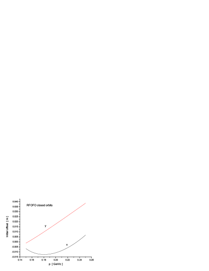
III.3 Closed orbits
Because of the symmetry of the magnetic field, radial and vertical deviations of the closed orbit must be even functions of s at any energy. This requires that their derivatives must be 0 at the ends of the period. This makes it easier to search for closed orbits because only variations in and need be considered. Muons were injected in the simulations at the boundary of the cell (the absorber central plane), where the transverse momentum vanishes for a closed orbit. For each initial (longitudinal) momentum, a unique closed orbit was determined by scanning the plane, and finding the point to which the muon returns every time it recrosses the absorber central plane. Since the magnetic field has a small radial component on-axis, the closed orbits are non-planar. The solid line in Fig. 8 shows the transverse motion of the closed orbit for a 201 MeV/c muon. Note that the closed orbit is offset by about 11 mm in and by about 17 mm in at the beginning of the cell. Along the cell varies by mm and varies by mm. The variation of the closed orbits for changes in momentum are also shown in Fig. 8.

III.4 Dispersion function
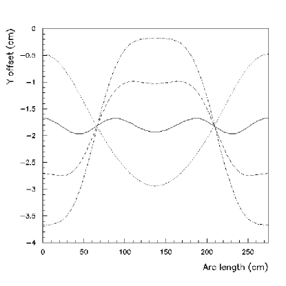
Dispersion functions in and at the absorber central plane (and approximately the absorber as a whole) can be derived from the closed orbits. One can see the linear dependence of the y (vertical) offset on the energy in Fig. 9. The dispersion at the absorber is approximately 8 cm in a direction from the axis.
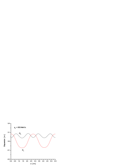
The dispersion at the center of the rf cavity has the opposite sign, and is also mostly in the direction. The vertical dispersion is surprisingly linear as a function of momentum, but the radial dispersion is not.
IV Cooling Simulations: Ideal Ring
We now turn to simulations of muon beams in the ring. For cooling studies we must now include the rf cavities and absorbers in the simulations.
Several merit factors have been defined for quantifying cooling performance.
| (2) |
For the M-factor is the normalized 6D emittance and is the total number of surviving muons at location For the D-factor, is the number of muons that are contained in a fixed transverse and longitudinal phase space acceptance volume after traversing a distance The M-factor is more relevant for a muon collider, while the D-factor would be more applicable to a neutrino factory. The Q-factor is a local variable R.B. Palmer (2002) that compares the rate of change of the emittance to the particle loss.
We first examine the performance of an ideal ring, ignoring for the moment additional effects due to windows on the absorbers and rf cavities and leaving empty space for injection. Several important ring parameters are listed in Table 2.
| Curvature (m) | 5.252 |
|---|---|
| Momentum compaction | |
| Transition energy factor | 8.09 |
| Slip factor | -0.198 |
| Longitudinal beta function (m) | 6.06 |
is the mean radius of curvature. The momentum compaction is the fractional change in circumference per fractional change in momentum. This ring always operates below the transition energy. The longitudinal beta function is given by E. Keil (2002)
| (3) |
where is the circumference of the ring, is the energy of the muons, is the relativistic velocity, is the unit of charge, is the peak rf voltage and is the synchronous phase. Note that is much larger than the transverse beta function
A reference particle was used to determine each cavity’s relative phase. The reference particle is a muon that runs in a closed orbit and is used as a clock to determine the rf frequency and set the entry times for each cavity in the ring. This clock satisfies the following conditions:
-
•
the revolution period is an integer multiple of the rf period
-
•
the muon momentum is around 200 MeV/c.
In GEANT the closed-orbit muon that was chosen as the reference particle has a momentum of 200.96 MeV/c. With a revolution period of 124.22 ns, its harmonic is 201.26 MHz. For the ICOOL runs we used a circular reference orbit.
Figure 10 shows the performance of the ideal ring as a function of distance. For the simulations we use a Gaussian input beam with normalized transverse emittance of 12 mm and normalized longitudinal emittance of 18 mm. The initial beam had a correlation between the axial momentum and the transverse amplitude to minimize the tendency for the particles in the bunch to spread out longitudinally in the solenoidal field. The correlation causes the average axial momentum to be larger than the reference momentum of 203 MeV/c.


A separate analysis that decoupled the emittance planes gave final normalized emittances mm, mm, and mm. After a distance of 495 m (15 turns) the 6D emittance has fallen by a factor of 240 with a transmission of 53% (66% without muon decay) and the M-factor is 120. The same factor for the U.S. Feasibility Study 2 (FS2) S. Ozaki, R. Palmer, M. Zisman, and J. Gallardo, eds. (2001) cooling lattice without windows is 15. This ideal ring has a maximum Q-factor of approximately 18.
We next consider the idealized ring behavior in terms of the muon density. Figure 11 shows the total muon transmission together with the muon density into two fixed acceptance volumes. These volumes correspond to the assumed acceptance of a linear accelerator that follows the cooling ring.
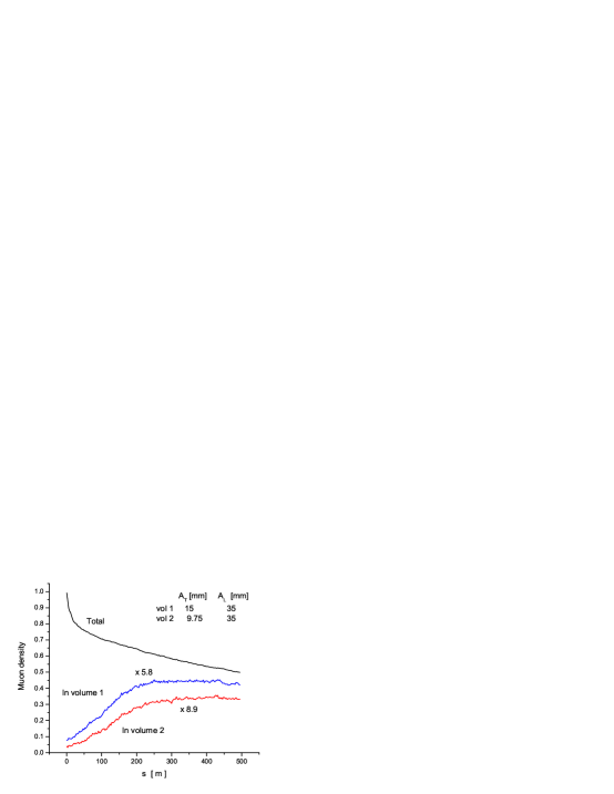
The idealized ring increases the muon density into the smaller acceptance volume by a factor of almost 9 in 250 m, which corresponds to about 8 turns. The density in the larger acceptance volume increases by about a factor of 6.
Figure 12 shows the radial and longitudinal phase space after 1 and 15 turns.
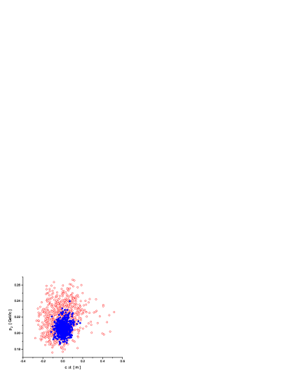
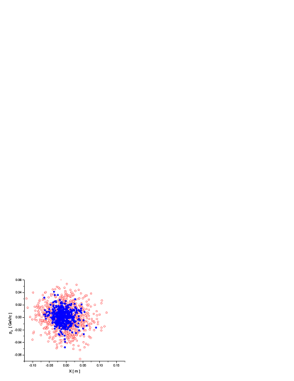
The reduction of phase space area can be seen clearly in both distributions. The vertical transverse distribution is similar to the radial one because of the mixing caused by the solenoids.
A comparison of ICOOL and GEANT performance calculations is shown in Fig. 13. The initial drop in transmission over the first few turns includes a contribution from scraping at transverse apertures due to mismatches between the initial beam distributions and the ring acceptance. The emittance was calculated using the program ECALC9 G. Penn ; R.C. Fernow (2003), which is a standard tool used for this purpose.
The agreement in calculated performance between the two codes is excellent.
V Cooling Simulations: Realistic Ring
We now consider the effects on performance of including windows for the absorbers and rf cavities and leaving empty cells for injection. We refer to this as the realistic ring design. Including windows introduces new sources of scattering and degrades the cooling performance. We enclose the liquid hydrogen absorbers with aluminum windows. The rf cavities have tapered beryllium windows. In general the M-factor is more sensitive to the presence of windows than the D-factor. Two adjacent cells have the absorber and rf cavities removed in order to leave space for the injection kicker, but the magnetic periodicity is maintained. We show the influence of these effects on the peak value of the D-factor in Table 3.
The absorber window used in FS2 was of aluminum. We see that windows of this thickness degrade the performance by about 30%. For safety reasons it may be necessary to use an additional window that increases the total amount of aluminum. On the other hand the use of other special materials or optimized window shapes could reduce the amount of material required. Another possibility would be to replace the liquid H2 absorber with a solid material. LiH is one possible candidate, although Table 3 shows there is a 45% loss of performance with this option.
| Absorber | Abs. Window | rf Window | Empty cells | D-factor |
|---|---|---|---|---|
| LH | none | none | 0 | 8.93 |
| LH | Al | none | 0 | 7.50 |
| LH | Al | none | 0 | 6.70 |
| LH | Al | none | 0 | 6.08 |
| LiH | none | none | 0 | 4.88 |
| LH | none | FS2 | 0 | 5.88 |
| LH | none | FS2/4 | 0 | 7.80 |
| LH | none | none | 2 | 6.73 |
| LH | Al | FS2/4 | 2 | 4.58 |
In FS2 the Be end windows on the rf cavities were m thick from the axis out to a radius of 12 cm, then m thick out to 18 cm. The interior windows were m thick from the axis to a radius of 14 cm, then m thick out to 21 cm. These rf windows degrade the performance by about 35%. One possibility to get around this problem is to operate the cavities at liquid nitrogen temperature. The lower operating temperature and the reduced rf gradient of 12 MV/m versus 16 MV/m in FS2 allow the thickness of the windows to be decreased by a factor of 4 with a performance loss of only 13%. An R&D program on low-temperature windows might permit further reduction in the rf window thicknesses. Alternatively, one could eliminate the rf cavity windows altogether and use an open cavity. This has the disadvantage that four times more power is required to produce the same on axis, assuming that surface breakdown does not limit the axial field available.
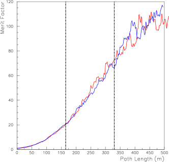
Introducing two empty cells for injection/extraction reduces the performance by 25%. Finally, we consider an example that combines all of these effects. We choose liquid H2 as the absorber with m thick windows and no safety windows. We assume that operation at liquid nitrogen temperature allows the thinner Be rf windows, and leave the empty cells in the lattice for injection/extraction. Figure 14 shows the evolution of the D-factor for the realistic ring.

The initial phase space volume used in this simulation had a normalized transverse acceptance of 9.75 mm and a normalized longitudinal acceptance of 35 mm. The muon density into the accelerator acceptance peaks after about 10 turns. This realistic ring model still gives an impressive increase in the accepted muon density of a factor of
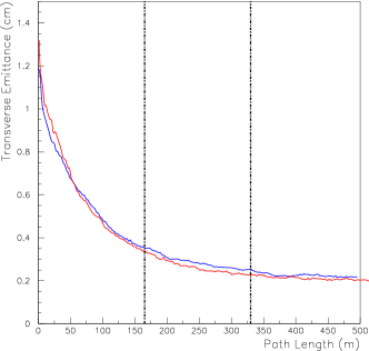
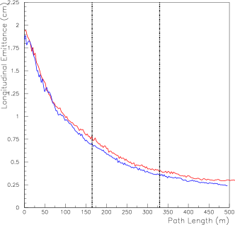
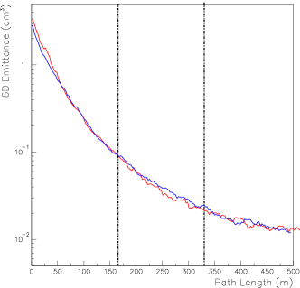
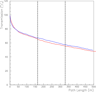
Figure 15 shows the evolution of the emittances and transmission for the realistic ring design.
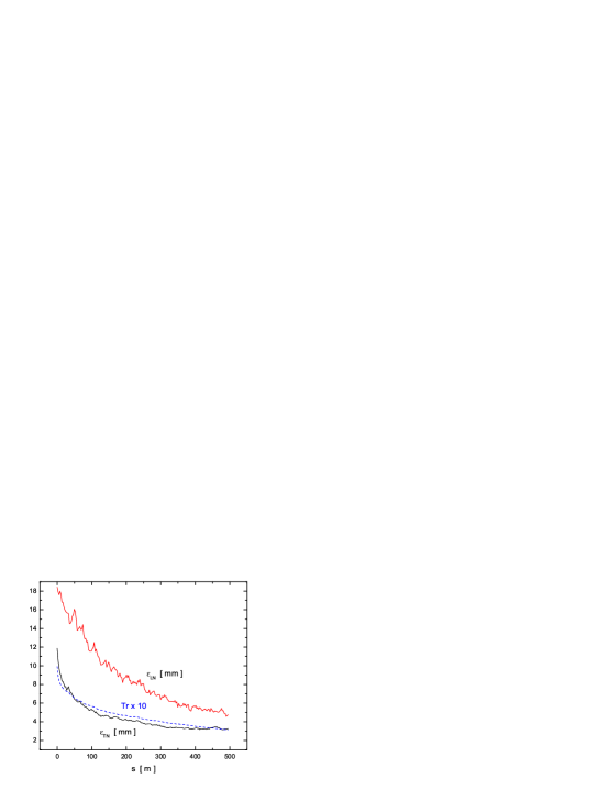
Some of the transverse losses originate from particles that initially slip out of the rf bucket. Following this there is a steady loss due to decays. Initially the emittance falls more rapidly than the because it is the emittance that is mainly exchanged with the longitudinal. But the Larmor rotations in the solenoids soon mix the and emittances, bringing them close to a common value. The emittance performance of the realistic ring is summarized in Table 4.
| Initial | Final | |
|---|---|---|
| (mm) | 11.9 | 3.3 |
| (mm) | 18.4 | 4.8 |
| (mm3) | 2830 | 58 |
| Tr (%) | 31 | |
| M | 15 |
The mean angle of muons at the end of the channel was 66 mr and the maximum angle for an accepted particle was 200 mr. This illustrates the advantage of using solenoidal focusing for this application. Although the realistic ring merit factors are reduced considerably from the ideal ring, where the corresponding merit factors were and the cooling performance is still quite significant.
VI Design Issues
There are a number of difficult design issues that must be resolved before a real ring cooler can be built. Each of the following areas needs a program of experimental R&D.
VI.1 Beam injection and extraction
The design of the injection-extraction channels and kickers will be challenging. The 12-fold symmetry of the ring must be broken to allow space for injection and extraction. In some simulations two cells have been modified for this purpose, as shown in Fig. 16.
A more detailed layout of the injection area is shown in Fig. 17.
The coils in the insertion area have been modified to allow muons from an external beamline to access the kicker. It is possible to generate magnetic fields in the insertion cells that are nearly identical to those in the rest of the ring.
The minimum pulsed energy required for the kicker is proportional to the square of the transverse emittance being kicked. Since the initial muon emittances discussed here are much larger than those encountered in other applications, such as antiproton accumulation, the energy in the pulsed kicker is three orders of magnitude greater, e.g. 10000 J here compared with 10–20 J for the antiprotons. However, magnetic amplifiers used in induction accelerators can provide this kind of pulse energy at the required pulse lengths, and a kicker design based on this concept has been proposed R.B. Palmer, L. Reginato, D. Summers (2002).
VI.2 Absorber heating
Using a ring for ionization cooling causes the beam bunches to pass through a given absorber many times. This results in the thermal load on the absorber in a ring being much larger than for the same absorber used in a linear channel. Consider the example shown in Table 5, which uses a 1 MW beam with similar parameters to FS2.
| Muons/bunch | |
| Bunch rep. rate (Hz) | 15 |
| Absorber length (cm) | 28.6 |
| Turns in the ring | 8 |
| Energy deposit/bunch (J) | 94 |
| Average beam radius (cm) | 4 |
| Temperature rise/bunch | 0.21 |
| Average power dissipated (kW) | 1.42 |
| Flow for | 1.45 |
| Velocity in 5 cm pipe (m/s) | 0.74 |
The average power deposited in the absorber exceeds 1.4 kW. The last two rows give the required water flow and velocity in a typical pipe to extract the heat under steady state conditions.
VI.3 RF windows
We have seen that the M-factor is very sensitive to the window thicknesses used in the simulations. Figure 18 shows how the M-factor for an early ring design depends on the rf window thickness.
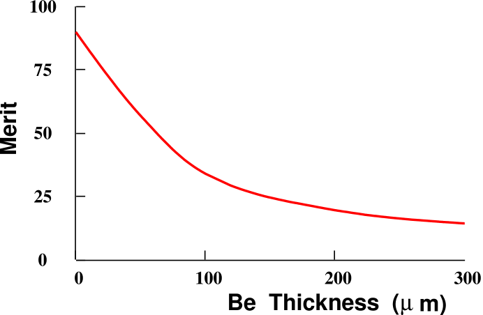
Thin windows are clearly advantageous, and we would like to use beryllium window thicknesses on the order of if possible. Cooling the cavity to liquid nitrogen temperatures would help.
VII Design Variations
We have also considered several variations of the 33 m circumference, 200 MHz ring discussed above.
VII.1 16.5 m circumference ring
We have simulated J.S. Berg, R.C. Fernow, R.B. Palmer (2002) a case with twice the bending field (0.25 T) and thus a ring circumference of only 16.5 m. Such a ring would require an even shorter initial bunch train, and is not expected to have as good a dynamic aperture. The transmission of an ideal ring after 15 turns was 45%, the transverse normalized emittance was cooled from 10.8 to 3.6 mm, the longitudinal normalized emittance was cooled from 51 to 5.2 mm, and the ideal M-factor was 40. The greater dispersion allowed a greater reduction in longitudinal emittance at the expense of less transverse cooling. The overall merit factor is not as good as the standard ring.
VII.2 66 m circumference ring
A larger circumference ring would allow a longer bunch length of the initial beam and would reduce problems with the injection kicker. The average vertical bending field was 0.064 T. The transmission of an ideal ring after 15 turns was 49%, the transverse normalized emittance was cooled from 11.9 to 2.0 mm, the longitudinal normalized emittance was reduced from 19 to 6.1 mm, the M-factor was 60, and the D-factor was 5.2. The smaller dispersion hurt the amount of longitudinal cooling and lowered the achievable merit factors.
VII.3 10 MHz ring
One solution to the problem of a long incoming bunch (train) is to reduce the rf frequency to 10 MHz. Simulations of the 33 m ring were done using a gradient of 2 MV/m and wedges. The transverse normalized emittance of an ideal ring was cooled from 18.6 to 2.9 mm, the longitudinal emittance was cooled from 251 to 79 mm and the M-factor was 61. The transverse cooling was good, but the longitudinal cooling needs more dispersion. The lower gradient was probably responsible for the slower cooling.
VII.4 Open rf cavities
It is also possible to use open rf cavities in the ring. This eliminates the scattering in the rf windows, but requires more rf power to achieve the same gradient. Simulations with 200 MHz open cavities in an ideal ring obtained the same performance as closed cavities with thick windows.
VII.5 Cylindrical absorber
We studied the effect of replacing the house shaped absorber with a more practical cylindrical shape. Simulations for an ideal ring using a cylindrical analog to the wedge gave an M-factor of 109 compared to 152 for the house shape.
VIII Conclusions
Cooling large emittance muon beams is important for neutrino factories and absolutely essential for a muon collider. Using a ring cooler geometry offers likely economic advantages in reusing expensive magnets, rf cavities and liquid hydrogen absorbers. A ring also provides a natural mechanism for obtaining longitudinal cooling through emittance exchange. The RFOFO ring cooler described here is at this time the most advanced ring cooler design. It uses realistic field modeling and takes into account the effects of windows on the absorbers and rf cavities and the effects of empty cells for injection and extraction.
The ring can increase the muon density in a standard acceptance volume by over a factor of 4. However, before such a ring could actually be built, a number of difficult technical issues, such as the injection kicker, need to be resolved through a program of experimental R&D. An intensive R&D program on rf and absorber windows is presently underway as part of the International Ionization Cooling experiment (MICE) Y. Torun (2003).
Acknowledgements.
This research was supported by the U.S. Department of Energy under Contracts No. DE-AC02-98CH10886, No. DE-AC02-76CH03000 and U.S. National Science Foundation under Award No. PHY-0104619.References
- M. M. Alsharo´a et al. (2003) M. M. Alsharo´a et al., Phys. Rev. ST Accel. Beams 6, 081001 (2003).
- C.M. Ankenbrandt, et al. (1999) C.M. Ankenbrandt, et al., Phys. Rev. ST Accel. Beams 2, 081001 (1999).
- R.B. Palmer (2003) R.B. Palmer, J.Phys. G 29, 1577 (2003).
- V. Balbekov et al. (2001) V. Balbekov et al., Proceedings of the 2001 Particle Accelerator Conference (2001), http://accelconf.web.cern.ch/Accel/Conf/p01/PAPERS/FPAH081.pdf.
- V. Balbekov, A. van Ginneken (1998) V. Balbekov, A. van Ginneken, AIP Conf. Proc. 441, 310 (1998).
- H. Kirk et al. (2003) H. Kirk et al., Muon Storage Ring for 6D Phase Space Cooling, Proceedings of the 2003 Particle Accelerator Conference (2003), http://accelconf.web.cern.ch/Accel/Conf/p03/PAPERS/WPAE%****␣rfofo.bbl␣Line␣50␣****029.pdf.
- D.J. Summers et al. (2001) D.J. Summers et al., 6D Ionization Muon Cooling with Tabletop Rings, eprint physics/0501071 (2001).
- (8) H. Kirk et al., private communication.
- J.S. Berg, R.C. Fernow, R.B. Palmer (2002) J.S. Berg, R.C. Fernow, R.B. Palmer, An Alternating Solenoid Focused Ionization Cooling Ring, MUC-NOTE-THEORY-239 (2002). This series of technical notes can be found at http://www-mucool.fnal.gov/mcnotes/.
- J.S. Berg, R.C. Fernow, R.B. Palmer (2003) J.S. Berg, R.C. Fernow, R.B. Palmer, J.Phys. G 29, 1657 (2003).
- R.C. Fernow et al. (2003) R.C. Fernow et al., Muon Cooling in the RFOFO Ring Cooler, Proceedings of the 2003 Particle Accelerator Conference (2003), http://accelconf.web.cern.ch/Accel/Conf/p03/PAPERS/WPAE027.pdf.
- J.S. Berg et al. (2004) J.S. Berg et al., AIP Conf. Proc. 721, 391 (2004), A. Para, ed.
- A. Klier, G.G. Hanson (2004) A. Klier, G.G. Hanson, Simulating the RFOFO Cooling Ring with GEANT, MUC-NOTE-THEORY-298 (2004).
- V. Balbekov (2002a) V. Balbekov, Investigation of RFOFO-like Cooling Rings, MUC-NOTE-THEORY-263 (2002a).
- V. Balbekov (2002b) V. Balbekov, Simulation of RFOFO Ring Cooler with Tilted Solenoids, MUC-NOTE-THEORY-264 (2002b).
- V. Balbekov (2003) V. Balbekov, Investigation and Simulation of Muon Cooling Ring with Tilted Solenoids, Proceedings of the 2003 Particle Accelerator Conference (2003), http://accelconf.web.cern.ch/Accel/Conf/p03/PAPERS/WPAE033.pdf.
- Fernow (1999) R. Fernow, in Proceedings of the 1999 Particle Accelerator Conference, edited by A. Luccio and W. MacKay (1999), p. 3020; latest version available at http://pubweb.bnl.gov/people/fernow/icool/readme.html.
- GEANT Manual v.3.21 (1994) GEANT Manual v.3.21, Detector Description and Simulation Tool, CERN Program Long Write-up W5013 (1994).
- R. Raja (2002) R. Raja, MUC_GEANT - Data Driven GEANT for Ring Coolers (2002).
- R.C. Fernow, J.C. Gallardo (2002) R.C. Fernow, J.C. Gallardo, Realistic on-axis Fields for the RFOFO Cooling Ring, MUC-NOTE-THEORY-265 (2002).
- S. Bracker (2003) S. Bracker, Magnetic Field Maps for the RFOFO Muon Cooling Ring, MUC-NOTE-THEORY-271 (2003).
- R.C. Fernow, J.C. Gallardo (2003) R.C. Fernow, J.C. Gallardo, Calculation of RFOFO Fields using the off-axis Expansion in ICOOL, MUC-NOTE-THEORY-268 (2003).
- R.B. Palmer (2002) R.B. Palmer, Cooling Efficiency Factor, MUC-NOTE-COOL-THEORY-250 (2002).
- E. Keil (2002) E. Keil, Muon Cooling Channels, MUC-NOTE-COOL-THEORY-257 (2002).
- S. Ozaki, R. Palmer, M. Zisman, and J. Gallardo, eds. (2001) S. Ozaki, R. Palmer, M. Zisman, and J. Gallardo, eds., Tech. Rep., BNL-52623 (2001), http://www.cap.bnl.gov/mumu/studyii/FS2-report.html.
- (26) G. Penn, ECALC9 , Fortran Code.
- R.C. Fernow (2003) R.C. Fernow, Physics Analysis performed by ECALC9, MUC-NOTE-COOL-THEORY-280 (2003).
- R.B. Palmer, L. Reginato, D. Summers (2002) R.B. Palmer, L. Reginato, D. Summers, An Induction Kicker for Muon Cooling Rings, MUC-NOTE-COOL-THEORY-256 (2002).
- Y. Torun (2003) Y. Torun, in Neutrino Factories and Superbeams, International Workshop NuFact03, edited by A. Para (AIP Conf. Proc., 2003), 721, p. 106.