Flicker noise in high-speed p-i-n photodiodes
Abstract
The microwave signal at the output of a photodiode that detects a modulated optical beam contains the phase noise and the amplitude noise of the detector. Beside the white noise, which is well understood, the spectral densities and show flicker noise, proportional to . We report on the measurement of the phase and amplitude noise of high-speed p-i-n photodiodes. The main result is that the flicker coefficient of the samples is ( ) for phase noise, and Hz-1 ( dB) for amplitude noise. These values could be observed only after solving a number of experimental problems and in a protected environment. By contrast, in ordinary conditions insufficient EMI isolation, and also insufficient mechanical isolation, are responsible for additional noise to be taken in. This suggests that if package and EMC are revisited, applications can take the full benefit from the surprisingly low noise of the p-i-n photodiodes.
1 Introduction
Many high performance applications of microwave photonics and optics are impacted by phase noise of the microwave signals modulated as sidebands on the optical carrier. Examples of such applications include the frequency distribution system in the NASA Deep Space Network [CWK+00], very long baseline radio astronomy interferometry arrays (VLBI) [SHK+00], laboratory time and frequency comparisons [NLL+03, BDKM99], photonic oscillators [YM96, YM97], and laser metrology [SLK01, IDH03]. The contributions of nearly all microwave and photonic circuit elements to the phase noise is, for most part, well understood, or at least determined experimentally. This is not the case for the contributions of the photodetector to the phase noise. Many high performance systems such as those mentioned above could be limited by the close-in noise of the photodetector. Yet the lack of information regarding this topic—only one conference article [SYML98] is found in the literature—made this work necessary. In this paper we describe a sensitive measurement technique for the close-in phase noise and amplitude noise, and the measurement of several photodetectors used to detect microwave (10 GHz) sidebands of optical carriers.
When a light beam is modulated in intensity by a microwave signal and fed into a photodetector, the detector delivers a copy of the microwave signal at its output, with added noise. Flicker noise is the random fluctuations of the microwave phase and of the fractional amplitude, and , with power spectrum density proportional to . This refers to the representation
| (1) |
The phase noise spectrum is of paramount importance because is related to time, which is the most precisely measured physical quantity. For a review on phase noise see the References [Rut78, CCI90, Vig99].
Most high-speed photodetectors are InGaAs p-i-n diodes operated in strong reverse-bias condition, hence as photoconductors. Reverse biasing is necessary for high speed because the high electric field reduces the transit time of the carriers, and also limits the junction capacitance. Thus, the depletion region (the intrinsic layer) can be tailored for quantum efficiency and speed. The p-i-n diode has the interesting property that even at relatively low reverse bias ( V) the junction capacitance is chiefly determined by the thickness of the i layer [Sze81, pp. 118–119], with little influence from . This indicates that phase noise may be lower than in other microwave devices.
2 Experimental method
A preliminary survey of the available detectors shows that none provides output power sufficient to use a saturated mixer as the phase detector, and that typical photodetectors have lower noise than common microwave amplifiers. Hence we opt for the bridge (interferometric) method, which permits flicker-free amplification before detection. This method, inspired to [San68], is now a well established technique. The full theory and an extensive description of the experimental aspects is available in [RG02]. Hence, the description given here focus on the adaptation of the bridge method to the measurement of the photodiodes.
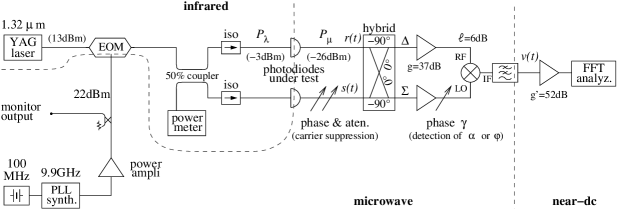
In our configuration (Fig. 1) the two detector outputs are combined with appropriate phase and amplitude, so that the sum () and the difference () are available at the output of the hybrid junction. At the equilibrium condition all of the microwave power goes in , while only the imbalance signal, i.e., the photodetector noise plus some residual carrier, is present in . Close-in flicker noise in amplifiers is a parametric effect that results from the flicker fluctuation of the dc bias that modulates the microwave carrier. Of course, the microwave output spectrum is white at zero or very low power. Hence the noise sidebands present in are amplified without adding flicker. The amplifier provides the power needed to saturate the LO port of the mixer, for it flickers. Yet it is shown in [RSYM03] that the close-in flickering of this amplifier is not detected because there is no carrier power on the other side of the mixer.
The detected signal, converted to dc by the mixer, is
| (2) |
where is the arbitrary phase that results from the circuit layout. Thus, the detection of amplitude or phase noise is selected by setting the value of . A fast Fourier transform (FFT) analyzer measures the output spectrum, or . The gain, defined as or , is
| (3) |
where is the amplifier gain, the microwave power, the characteristic resistance, and the mixer ssb loss. Under the conditions of our setup (see below) the gain is , including the dc preamplifier. The notation means that /rad appears when appropriate.
Calibration involves the assessment of and the adjustment of . The gain is measured through the carrier power at the diode output, obtained as the power at the mixer RF port when only one detector is present (no carrier suppression takes place) divided by the detector-to-mixer gain. This measurement relies on a power meter and on a network analyzer. The detection angle is first set by inserting a reference phase modulator in series with one detector, and nulling the output by inspection with a lock-in amplifier. Under this condition the system detect . After adding a reference 90∘ to , based either on a network analyzer or on the calibration of the phase shifter, the system detects . The phase modulator is subsequently removed to achieve a higher sensitivity in the final measurements. Removing the modulator is possible and free from errors because the phase relationship at the mixer inputs is rigidly determined by the carrier suppression in , which exhibits the accuracy of a null measurement.
The background white noise results from thermal and shot noise. The thermal noise contribution is
| (4) |
where is the noise figure of the amplifier, and J is the thermal energy at room temperature. This is proved by dividing the voltage spectrum detected when the amplifier is input-terminated, by the square gain . The shot noise contribution of each detector is
| (5) |
where is the electron charge, is the detector responsivity, the index of intensity modulation, and the average optical power. This is proved by dividing the spectrum density of the the output current by the average square microwave current . The background amplitude and phase white noise take the same value because they result from additive random processes, and because the instrument gain is the same. The residual flicker noise is to be determined experimentally.
The differential delay of the two branches of the bridge is kept small enough (nanoseconds) so that a discriminator effect does not take place. With this conditions, the phase noise of the microwave source and of the electro-optic modulator (EOM) is rejected. The amplitude noise of the source is rejected to the same degree of the carrier attenuation in , as results from the general properties of the balanced bridge. This rejection applies to amplitude noise and to the laser relative intensity noise (RIN).
The power of the microwave source is set for the maximum modulation index , which is the Bessel function that results from the sinusoidal response of the EOM. This choice also provides increased rejection of the amplitude noise of the microwave source. The sinusoidal response of the EOM results in harmonic distortion, mainly of odd order; however, these harmonics are out of the system bandwidth. The photodetectors are operated with some 0.5 mW input power, which is low enough for the detectors to operate in a linear regime. This makes possible a high carrier suppression (50–60 dB) in , which is stable for the duration of the measurement (half an hour), and also provides a high rejection of the laser RIN and of the noise of the amplifier. The coherence length of the YAG laser used in our experiment is about 1 km, and all optical signals in the system are highly coherent.
3 Results
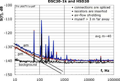
The background noise of the instrument is measured in two steps. A first value is measured by replacing the photodetectors output with two microwave signals of the same power, derived from the main source. The noise of the source is rejected by the bridge measurement. A more subtle mechanism, which is not detected by the first measurement, is due to the fluctuation of the mixer offset voltage induced by the fluctuation of the LO power [BMU77]. This effect is measured in a second test, by restoring the photodetectors and breaking the path from the hybrid junction to the amplifier, and terminating the two free ends. The worst case is used as the background noise. The background thereby obtained places an upper bound for the noise, yet hides the shot noise. This is correct because the shot noise arises in the photodiodes, not in the instrument. The design criteria of Sec. 2 result in a background flicker of approximately at Hz, hardly visible above 10 Hz (Fig. 2). The white noise, about , is close to the expected value, within a fraction of a decibel. It is used only as a diagnostic check, to validate the calibration.
We tested three photodetectors, a Fermionics HSD30, a Discovery Semiconductors DSC30-1k, and a Lasertron QDMH3. These devices are InGaAs p-i-n photodiodes suitable to the wavelength of 1.3 m and 1.55 m, exhibiting and a bandwidth in excess of 12 GHz, and similar to one another. They are routinely used in our photonic oscillators [YM96, YM97] and in related experiments.
Each measurement was repeated numerous times with different averaging samples in order to detect any degradation from low-frequency or non-stationary phenomena, if present. Figure 2 shows an example of the measured spectra. Combining the experimental data, we calculate the flicker of each device, shown in Table 1. Each spectrum is affected by a random uncertainty is of 0.5 dB, due to the parametric spectral estimation (Ref. [PW98], chap. 9), and to the measurement of the photodetector output power. In addition, we account for a systematic uncertainty of 1 dB due to the calibration of the gain. The random uncertainty is amplified in the process of calculating the noise of the individual detector from the available spectra. Conversely, the systematic uncertainty is a constant error that applies to all measurements, for it is not amplified.
| photodiode | ||||||||
|---|---|---|---|---|---|---|---|---|
| estimate | uncertainty | estimate | uncertainty | |||||
| HSD30 |
|
|
||||||
| DSC30-1K |
|
|
||||||
| QDMH3 |
|
|
||||||
| unit | dB/Hz | dB | dB | |||||
4 Discussion
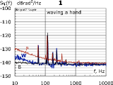
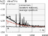
For practical reasons, we selected the configurations that give reproducible spectra with low and smooth noise that are not influenced by the sample averaging size. Reproducibility is related to smoothness because technical noise shows up at very low frequencies, while we expect from semiconductors smooth noise in a wide frequency range. Smoothness was verified by comparison with a database of trusted spectra. Technical noise turned out to be a serious difficulty. As no data was found in the literature, we give some practical hints in Fig. 3.
The EOM requires a high microwave power (20 dBm or more), which is some 50 dB higher than the photodetector output. The isolation in the microwave circuits is hardly higher than about 120 dB. Thus crosstalk, influenced by the fluctuating dielectric constant of the environment, turns into a detectable signal. The system clearly senses the experimentalist waving a hand ( m/s) at a distance of 3 m. The spectrum (Fig. 3.1, plot W) is easily taken for flicker. This problem can be mitigated using the new high-efficiency EOMs [vE02].
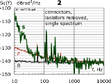
Air flow affects the delay of the optical fibers, thus some isolation is necessary to mitigate this effect. All our attempts failed until we inserted optical isolators in series with the photodetectors, and spliced all the fiber junctions (except the laser output). After this, the back-reflected light at the unused port of the coupler was below the sensitivity of the power-meter, which is 1 nW. Without isolation and splicing, individual spectra show spikes appearing at random times (Fig. 3.2, plot S). Averaging yields a smooth spectrum. Yet slope is incorrect (Fig. 3.3, plot A). Beside the mechanics of the connectors, we attribute this effect to reflection noise in the optical fibers [lGC89, SM98].
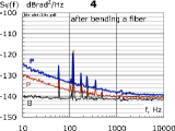
Even after isolating and splicing, we observed that bending a fiber may result in increased flickering. Afterwards, the spectrum may become irregular, or still be smooth with a clean slope, as in Fig. 3.4, plot F, but nevertheless incorrect. We interpret this as a change in the interference pattern in the fiber due to polarization. The observed increase in noise is clearly systematic, although reproducing the numerical value takes some effort.
Spectral lines at 60 Hz and its multiples are present in the noise spectra, originated by magnetic fields, in all cases lower than . The level of these stray signals is about the same found routinely in the phase noise measurement with the saturated mixer method, yet with a carrier power of some 10 dBm instead of the dBm of our experiments, thus with a signal-to-noise ratio proportionally higher. The superior immunity of the bridge scheme is due to microwave amplification of the noise sidebands before detecting.
The spectra of the detectors we measured are similar, and a value of at Hz can be taken as representative of both amplitude and phase noise. Using the formulae available in [Rut78, CCI90, Vig99], a spectrum of the form converted into the Allan (two-sample) variance is independent of the measurement time . The length of 1 rad in a fiber of refraction index , at the modulation frequency GHz, of is 3.3 mm. Thus a phase noise of at Hz () is equivalent to a fluctuation nm of the optical length .
5 Final remarks
It is generally accepted [Sik03] that flicker noise is an elusive phenomenon and that our understanding is based on models, the most accreditated of which are due to Hooge [Hoo69] and to McWhorter [McW57], rather than on a unified theory. On the other hand, the presence of the phase and amplitude flickering in a microwave carrier is believed to be the dc flicker, up-converted by a nonlinearity. This also applies to the photodiode, even though in this case the dc bias exists only in the presence of light. In fact, removing the modulation results in a white microwave spectrum, flat around any frequency in the passband of the ststem.
The experimental difficulties we encountered are due to various forms of technical noise, at an exceedingly low level, which nevertheless may exceed the detector noise, unless great care is taken. On one hand, this means that the environment in which the diode is inserted must be revisited if one needs the lowest achievable noise. On the other hand, this means that the photodiode exhibits low noise and high stability, and that it has an unexploited potential for new and emerging applications.
Acknowledgements
The research described in this paper was carried out at the Jet Propulsion Laboratory, California Institute of Technology, under contract of the National Aeronautics and Space Administration, and with support from ARL and AOSP / DARPA. We thank the Université Henri Poincaré for partially supporting E. Rubiola while visiting JPL, and F. Lardet-Vieudrin of FEMTO-ST, France, for providing low-flicker dc preamplifiers.
References
- [BDKM99] M.-B. Bibey, F. Deborgies, M. Karakowsky, and D. Mongardien, Very low phase noise optical links—experiments and theory, IEEE Trans. Microw. Theory Tech. 47 (1999), no. 12, 2257–2262.
- [BMU77] Rémi Brendel, Gilles Marianneau, and Jean Ubersfeld, Phase and amplitude modulation effects in a phase detector using an incorrectly balanced mixer, IEEE Trans. Instrum. Meas. 26 (1977), no. 2, 98–102.
- [CCI90] CCIR Study Group VII, Characterization of frequency and phase noise, Report no. 580-3, Standard Frequencies and Time Signals, Recommendations and Reports of the CCIR, vol. VII (annex), International Telecommunication Union (ITU), Geneva, Switzerland, 1990, pp. 160–171.
- [CWK+00] M. Calhoun, R. Wang, A. Kirk, G. J. Dick, and R. L. Tjoelker, Stabilized reference frequency distribution for radio sciencewith the Cassini spacecraft and the deep space network, Proc. Precision Time and Time Interval Conf. (USA), November 28-30 2000, pp. 331–340.
- [Hoo69] Friits N. Hooge, noise is no surface effect, Phys. Lett. A 29 (1969), 139–140.
- [IDH03] E. N. Ivanov, S. A. Diddams, and L. Hollberg, Analysis of noise mechanisms limiting the frequency stability of microwave signals generated with a femtosecond laser, J. Selected Topics Quantum Elec. 9 (2003), no. 4, 1059–1065.
- [lGC89] James l Gimlett and Nim K. Cheung, Effects of phase-to-intensity noise conversion by multiple reflections on gigabit-per-second DFB laser transmission systems, J. Ligtwave Technol. 7 (1989), no. 6, 888–895.
- [McW57] A. L. McWhorter, noise and germanium surface properties, Semiconductor Surface Physics (R. H. Kingston, ed.), University of Pennsylvania Press, Philadelphia, 1957, pp. 207–228.
- [NLL+03] F. Narbonneau, M. Lours, O. Lopez, A. Clairon, and G. Santarelli, Ultra-stable optical links for metrological applications, Proc. Freq. Control Symp. and European Freq. and Time Forum Joint Meeting (Tampa, FL), May 5–8, 2003, pp. 1041–1047.
- [PW98] Donald B. Percival and Andrew T. Walden, Spectral analysis for physical applications, Cambridge, Cambridge, UK, 1998.
- [RG02] Enrico Rubiola and Vincent Giordano, Advanced interferometric phase and amplitude noise measurements, Rev. Sci. Instrum. 73 (2002), no. 6, 2445–2457.
- [RSYM03] Enrico Rubiola, Ertan Salik, Nan Yu, and Lute Maleki, Phase noise measurement of low power signals, Electron. Lett. 39 (2003), no. 19, 1389–1390.
- [Rut78] Jacques Rutman, Characterization of phase and frequency instabilities in precision frequency sources: Fifteen years of progress, Proc. IEEE 66 (1978), no. 9, 1048–1075.
- [San68] K. H. Sann, The measurement of near-carrier noise in microwave amplifiers, IEEE Trans. Microw. Theory Tech. 9 (1968), 761–766.
- [SHK+00] Katsuhisa Sato, Tadayoshi Hara, Seisuke Kuji, Kazuyoshi Asari, Masanori Nishio, and Nobuyuki Kawano, Development of an ultrastable fiber optic frequency distribution system using an optical delay control module, IEEE Trans. Instrum. Meas. 1 (2000), no. 49, 19–24.
- [Sik03] Josef Sikula (ed.), Noise and fluctuations, CNRL, Brno, Czech Republic, 2003, Proc. 2003 Intl. Conf. on Noise and Fluctuations.
- [SLK01] Ryan P. Scott, Carsten Langrock, and Brian H. Kolner, High-dynamic-range laser amplitude and phase noise measurement techniques, J. Selected Topics Quantum Elec. 7 (2001), no. 4, 641–655.
- [SM98] William Shieh and Lute Maleki, Phase noise of optical interference in photonic RF systems, IEEE Photonic Technology Lett. 10 (1998), no. 11, 1617–1619.
- [SYML98] W. Shieh, X. S. Yao, L. Maleki, and G. Lutes, Phase-noise chracterization of optoelectronic components by carrier suppression techniques, Proc. Optical Fiber Comm. (OFC) Conf. (San José, CA), May 23-25 1998, pp. 263–264.
- [Sze81] S. M. Sze, Physics of semiconductor devices, 2nd ed., Wiley, New York, 1981.
- [vE02] Timothy van Eck, Polymer modulators for RF photonics, RF Photonic Technology in Optical Fiber Links (William S. C. Chang, ed.), Cambridge, Cambridge, UK, 2002, pp. 203–229.
- [Vig99] John R. Vig (chair.), IEEE standard definitions of physical quantities for fundamental frequency and time metrology–random instabilities (IEEE standard 1139-1999), IEEE, New York, 1999.
- [YM96] X. Steve Yao and Lute Maleki, Optoelectronic microwave oscillator, J. Opt. Soc. Am. B - Opt. Phys. 13 (1996), no. 8, 1725–1735.
- [YM97] , Dual microwave and optical oscillator, Optics Lett. 22 (1997), no. 24, 1867–1869.