A high-accuracy optical clock via three-level coherence in neutral bosonic 88Sr
Abstract
An optical atomic clock scheme is developed that utilizes two lasers to establish coherent coupling between the ground state of 88Sr and the first excited state, . The coupling is mediated by the broad state, exploiting the phenomenon of electromagnetically induced transparency. The effective linewidth of the clock transition can be chosen at will by adjusting the laser intensity. By trapping the 88Sr atoms in an optical lattice, long interaction times with the two lasers are ensured; Doppler and recoil effects are eliminated. Based on a careful analysis of systematic errors, a clock accuracy of better than is expected.
pacs:
42.62.Eh, 32.80.-t, 32.70.Jz, 42.62.FiArmed with superior resonance quality factors, optical atomic clocks based on single trapped ions or a collection of laser cooled neutral atoms are expected to outperform microwave-based atomic clocks in the near future Didd01 ; Oate99 ; Wilp02 . While a large number of quantum absorbers in a neutral atom system provide an advantage in the enhanced short-term frequency stability, atomic motion during the probe phase seriously limits the attainable accuracy. A competitive proposal is to localize neutral cold atoms spatially in a Lamb-Dicke regime while the trapping potential is designed such that its presence does not influence the clock transition frequency IdKa03 . This scheme can be potentially realized using a far-off-resonance dipole trap operating at a wavelength where the ground and the excited state of the clock transition experience exactly the same AC Stark shifts. In particular, if the atoms are confined near the ground vibrational levels in an optical lattice, frequency shifts associated with effects such as Doppler, collision, and recoil will all be reduced to negligible levels.
To realize such a scheme, it is of essential importance that the polarizabilities of the two clock states are matched to a high degree of accuracy at the “magic” wavelength KaTa03 . States with scalar polarizabilities are preferred, to avoid the problem of the complex and sometimes uncontrolled light polarization inside an optical lattice. The fermionic strontium isotope, 87Sr, offers a nearly satisfactory solution KaTa03 ; TaKa03 . The nuclear magnetic dipole moment of 87Sr makes the – transition weakly dipole allowed, with a predicted linewidth of about 1 mHz KaTa03 ; SaCh04 ; PoDe04 . The two clock states have very small electronic angular momenta (due to hyperfine mixing) and their polarizabilities are nearly scalar. However, the hyperfine structure can cause a clock frequency shift (possibly as large as 10 Hz) by fluctuations of the lattice light polarization. The large nuclear spin () also brings complexity in state preparation and field control.
In this Letter, we propose a scheme for an optical clock that is based on states of true scalar nature, namely – of 88Sr (with ). A direct transition between these two states is of course completely forbidden, and the clock scheme is based instead on three-level quantum coherence established by two probe laser frequencies. We note that recently a scheme has emerged based on four levels and three probe lasers HoCr04 . An estimate of the expected accuracy for this scheme is not yet available. A scheme similar to what is discussed here was investigated for trapped ions siemers .
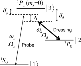
Our proposal rests on the three-level lambda-type scheme shown in Fig. 1. Particularly promising in this context is strontium IdKa03 ; TaKa03 ; KaTa03 ; XuLo03 , which we consider here in detail. A similar scheme is conceivable for bosonic isotopes of other alkaline-earth species (including ytterbium). Since the ground state ()—subsequently denoted by the state vector —and the first excited state ()——of 88Sr are characterized by a total angular momentum of , electric and magnetic one-photon transition matrix elements between these two states vanish to any multipole order. decays radiatively via E1M1 two-photon emission after a lifetime of a few thousand years SaCh04 . For practical purposes, it is therefore legitimate to set the decay width of equal to zero. The state, which is referred to as in our scheme, can be reached from via E1 one-photon absorption using a probe laser at a wavelength of nm (frequency ). One M1 photon from a dressing laser at nm (frequency ) is needed to resonantly couple and . The latter decays primarily to . The decay width is MHz.
Assuming linear polarization of both the probe and the dressing lasers, and assuming that the electric component of the probe laser (amplitude ) and the magnetic component of the dressing laser (amplitude ) are aligned along the same axis, level is characterized by for our purposes. Let denote the Rabi frequency associated with electric-dipole coupling between levels and . Similarly, is the Rabi frequency referring to the dressing process. and may be taken to be real.
We first analyze the dressed-atom problem within the subspace spanned by and in the absence of the probe laser. The equations of motion in the interaction picture read
| (1) | |||||
| (2) |
where () and () represent probability amplitudes and the rotating-wave approximation has been applied. The dressing laser detuning is [ stands for the unperturbed frequency of , ].
Due to the action of , some character is admixed to (and vice versa), so that a long-lived dressed state, , emerges whose decay rate can be adjusted through the dressing laser intensity. It is easily seen that to leading order with respect to
| (3) |
Here,
| (4) |
It follows from the equation for that for small detuning the decay rate of is . The dressed state deriving primarily from decays with a rate that is virtually identical to .
Using the atomic structure code described in Ref. SaCh04 , which accurately treats electron correlation and spin-orbit effects in the valence shell, we obtain for the magnetic coupling matrix element . Hence, if an effective width of, say, 1 mHz is desired (similar to the 87Sr case), a dressing laser intensity of 3.9 mW/cm2 must be chosen and is used for numerical results presented in this paper. (By decreasing the intensity, the effective linewidth can be made even narrower.) Under these circumstances, the parameter in Eqs. (3) and (4), which describes the degree of admixture of character in the long-lived dressed state, has a magnitude of less than . In other words, the dressed states in this scheme are hardly distinguishable from bare atomic states. We will exploit this fact later when estimating level shifts caused by sources not included in the simple three-level picture of Fig. 1.
Since there is no direct coupling between and , it is apparent from Eq. (3) that the transition associated with the long-lived dressed state can only be probed from the ground state by tuning in the vicinity of , i.e. in the vicinity of the broad absorption profile of level 3. Hence, . The long-lived and the short-lived states are excited in a coherent fashion by the probe laser. They interfere and give rise to a narrow dip structure in the absorption profile—an effect known as electromagnetically induced transparency (EIT) Harr97 . This dip is more than times narrower ( mHz) than the bare absorption profile of level 3. The broad background is therefore essentially constant across the narrow structure.
This quantum interference may be treated, to a first approximation, within a wave function-based approach, but it fails to take into consideration the repopulation of via spontaneous emission from . More importantly, the loss of coherence between levels and cannot be described. Decoherence is caused by lattice-induced spontaneous emission, atomic tunneling between adjacent sites in the optical lattice and ensuing collisions between the atoms. Another factor is the loss of phase coherence between the probe and the dressing laser. Both aspects must be included in a realistic description. Utilizing standard density-matrix theory BrHa75 , the absorption rate from the ground state is found to be
| (5) |
where , and stands for the loss rate of coherence between and .
If the dressing laser is off, or if , the simple Lorentzian profile connected with the transition from to is recovered. Otherwise, if we disregard for a moment, the absorption rate vanishes at . Note that the occurrence of a zero in this absorption profile is clear from the connection of this problem to the Fano Fano61 lineshape for one bound state (level 2 upshifted by the energy of one dressing laser photon) embedded in one “continuum” (the 32 MHz wide state). A deep, narrow dip occurs in the absorption profile note , and the width of the EIT dip for is
| (6) |
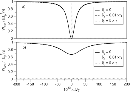
This demonstrates that not only the position of the EIT dip, but also its width is very insensitive with respect to fluctuations of . A variation of the dressing laser frequency by as much as 100 kHz induces a relative change of the EIT width of less than . The effect is illustrated in Fig. 2(a) (). Hence, by measuring as a function of , the clock frequency can be determined with high accuracy by tracking the position of the dip. Neither nor must be particularly stable, only the difference needs to be stabilized.
Also shown in Fig. 2(a) is the absorption profile near for relatively large detuning (). Overall, the signal amplitude is drastically reduced in this case. There is a narrow absorption peak in the immediate vicinity of , but, as can be seen in Fig. 2(b), this peak all but disappears as soon as decoherence becomes appreciable. (We have chosen in Fig. 2(b).) On the other hand, for small detuning the EIT dip is still clearly visible, even though it is not as deep as in the absence of decoherence and it has become broader. The position of the EIT minimum and the insensitivity of the EIT width with respect to laser frequency ( or ) fluctuations of 100 kHz or so are essentially unaffected.
The discussion has so far covered only resonant couplings within the span of , , and . In order to evaluate the potential accuracy of the proposed clock scheme, we need to consider the AC Stark shifts due to nonresonant electric dipole coupling of , , and to states inside and outside the three-level subspace. Our calculation of these shifts employs accurate experimental and theoretical data on excitation energies and oscillator strengths of atomic Sr IdKa03 ; WeGr92 ; UeAs82 . For a probe laser intensity of 10 W/cm2, levels 1 and 2 are AC Stark-shifted by less than 1 mHz. The dressing laser, operating at an intensity of 3.9 mW/cm2, causes an AC Stark shift of levels 1 and 2 of -41 mHz and -20 mHz, respectively. Thus, the clock frequency is systematically shifted by about +19 mHz. Since the intensity of the dressing laser can be stabilized to better than 1 %, we conclude that the AC Stark effect due to the probe and dressing lasers can be experimentally characterized at the sub-mHz level.
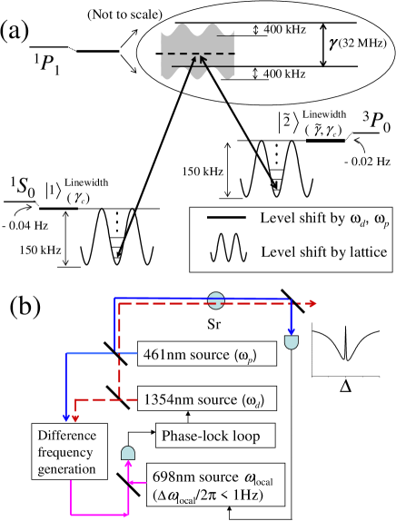
To allow for a sufficiently long interrogation time and eliminate systematic frequency shifts associated with atomic motion, the atoms will be confined in a Lamb-Dicke regime in an optical lattice at the magic wavelength for the clock transition, as shown in Fig. 3(a). The lattice trapping field causes, to leading order, no net frequency shift of the clock transition as the level shifts of 1 and 2 (150 kHz well depth in Fig. 3(a), under a lattice laser intensity of 10 kW/cm2) are exactly matched. (The studies in Ref. KaTa03 suggest that higher-order AC Stark effects are negligible at this lattice laser intensity.) Level 3 in our scheme, however, is shifted relative to levels 1 and 2, and this shift depends on the local intensity an atom experiences in the lattice. We calculate a relative shift of -250 kHz (maximum in magnitude), at a lattice laser intensity of 10 kW/cm2 and a magic wavelength of 813.5 nm TaKa03 . Figure 3(a) shows the lattice-induced shift of level 3 in comparison to . This shift is similar—in effect and in magnitude—to the drift of the probe and dressing laser frequencies. It has, therefore, an equally negligible effect on the properties of the EIT dip.
To make the final estimate of the clock accuracy, the level shifts shown in Fig. 3(a) contain the AC Stark shifts due to the simultaneous presence of and laser fields as discussed above. The lattice field induces a spontaneous emission limited linewidth of the clock transition at 15 mHz. The detuning and decoherence-(laser frequency variations, atomic motion inside lattice, spontaneous emission, etc)-related changes in the EIT linewidth may lead to a small shift in the experimental search of the linecenter, but the shift magnitude is estimated to be under . The blackbody radiation induced clock frequency shift is estimated to be -0.54 Hz at 300 K, with a temperature coefficient of -7.5 mHz/K. Finally, the strict scalar nature of the clock transition reduces the light polarization and stray magnetic field-induced frequency shift below . In view of the available control accuracy of the laboratory temperature and the dressing laser intensity, the overall accuracy limit is estimated to be smaller than 8 mHz, or .
Experimental implementation of this EIT-based clock scheme is shown in Fig. 3(b). A narrow linewidth ( 1 Hz) laser at 698 nm () will be developed by prestabilizing to a stable, passive optical cavity. The difference frequency, , between the probe laser and the dressing laser, generated by a nonlinear optical crystal, will be phase locked to the 698 nm local oscillator. One of the two lasers, such as , as shown in Fig. 3(b), can be used as the slave to accomplish the optical phase lock loop. Thus, = . This is prestabilization, implemented before and interact with the atoms. and may fluctuate on the order of 100 kHz, but their difference fluctuates less than 1 Hz.
The frequency of can be precisely scanned with reference to a stable cavity mode, which of course has an inevitable slow frequency drift due to the material nature of the reference. However, precise scanning of through the EIT resonance enables one to activate a slow feedback loop to stabilize to the value of , i.e., the quantum resonance corrects the long-term drift of the cavity resonance according to the clock transition frequency. The feedback is applied directly on the 698 nm local oscillator () to ensure = 0.
The tunability of the linewidth, the exquisite insensitivity with respect to light polarization in the optical lattice, the straightforward state control, and the small, controllable AC Stark shifts promise that our EIT-based clock scheme using bosonic 88Sr will represent a practical and robust approach for optical atomic clocks with a competitive performance in both stability and accuracy.
Acknowledgements.
We thank M. Boyd, A. Ludlow, T. Loftus, J. Hall, S. Yelin, and M. Lukin for stimulating discussions. Funding is provided by NSF, NIST, ONR, and NASA. J. Ye’s email Ye@jila.colorado.edu.References
- (1) S. A. Diddams et al., Science 293, 825 (2001).
- (2) C. W. Oates et al., Eur. Phys. J. D 7, 449 (1999).
- (3) G. Wilpers et al., Phys. Rev. Lett. 89, 230801 (2002).
- (4) T. Ido and H. Katori, Phys. Rev. Lett. 91, 053001 (2003).
- (5) H. Katori et al., Phys. Rev. Lett. 91, 173005 (2003).
- (6) M. Takamoto and H. Katori, Phys. Rev. Lett. 91, 223001 (2003).
- (7) R. Santra, K. V. Christ, and C. H. Greene, Phys. Rev. A 69, 042510 (2004).
- (8) S. G. Porsev and A. Derevianko, Phys. Rev. A 69, 042506 (2004).
- (9) T. Hong et al., arXiv:physics/0409051 (2004).
- (10) I. Siemers at al, Europhys. Lett. 18, 139 (1992).
- (11) X. Xu et al., J. Opt. Soc. Am. B 20, 968 (2003); I. Courtillot et al., Phys. Rev. A 68, 030501(R) (2003).; X. Xu et al., Phys. Rev. Lett. 90, 193002 (2003); G. Ferrari et al., Phys. Rev. Lett. 91, 243002 (2003); D. E. Chang, J. Ye, and M. D. Lukin, Phys. Rev. A 69, 023810 (2004); T. H. Loftus et al., Phys. Rev. Lett. 93, 073003 (2004); T. Ido et al., arXiv:physics/0410110 (2004); I. Courtillot et al., arXiv:physics/0410108 (2004).
- (12) S. E. Harris, Phys. Today 50, No. 7, 36 (1997).
- (13) R. G. Brewer and E. L. Hahn, Phys. Rev. A 11, 1641 (1975).
- (14) U. Fano, Phys. Rev. 124, 1866 (1961).
- (15) The absence of AC Stark shifts associated with the dressing and probe lasers acting within the three level system was pointed out in siemers and references therein.
- (16) H. G. C. Werij et al., Phys. Rev. A 46, 1248 (1992).
- (17) K. Ueda, Y. Ashizawa, and K. Fukuda, J. Phys. Soc. Jpn. 51, 1936 (1982).