Doppler effects in a left-handed material: a first-principle theoretical study
Abstract
The Doppler effects for the reflected wave from a moving media are systemically analyzed in this paper. The theoretical formula for the Doppler shift in the left-handed material, which is described by Drude’s dispersion model, is presented. This formula is examined by first-principles numerical experiments, which are in agreement with the theoretical results.
pacs:
78.20.Ci, 42.25. Bs, 41.20.JbKeywords: left-handed material; wave Propagation; doppler Effect; numerical simulation.
I INTRODUCTION
The Doppler effect is a well-known phenomenon that the frequency of a wave emitting from a moving object is shifted from the source frequency, originally discovered by Christian Doppler in 1843 Doppler1843P1 ; Papasbook . Conventional Doppler shift tells us that the measured frequency will increase when a source and observe approach each other. In virtue of this effect, an immense variety of novel applications are widely established including weather and aircraft radar system, blood flow measurement, and discovery of new planets and binary stars. The inverse Doppler effect refers to frequency shifts that are in the opposite sense to those mentioned above. It has been observed in a dielectric-loaded stripline cyclotron-resonance maser oscillator Einat1997P1 , the moving shock wave propagating through a photonic crystals Reed2003P1 and the moving boundary in an electrical transmission line Seddon2003P1 . In fact, back to 1968, the inverse Doppler effect has been already predicted to occur in a left-handed material (LHM) with simultaneously negative permittivity and permeability Veselago1968 . Pendry et al. discovered a microwave-plasma thin-wire structure exhibiting negative permittivity below the electronic plasma frequency Pendry1996P1 and a magnet-free split-ring resonator structure exhibiting negative permeability below the magnetic plasma frequency Pendry1999P1 . With the suggestion of Pendry’s theory, the first experimental verification of a LHM was demonstrated Shelby2001 , which has recently received much attention in the literature Smith2002P1 ; Smith2003P1 ; Xiao2004P2 ; Yen2004P1 ; Xiao2004P3 . However, up to our knowledge, inverse Doppler effect in a left-handed material has not been demonstrated experimentally yet, not even by numerical experiments.
In this paper, we will study Doppler effects for the reflected wave from a moving media and present theoretical formula for the Doppler shift, which will be examined by first-principles numerical experiments using the finite difference time domain (FDTD) method.
II MODEL AND THEORETICAL FORMULA
Consider a plane electromagnetic wave propagation in medium I and incident at an angle on an idealized moving medium II. The incident wave have an angular frequency and a propagation vector (In a LHM, the direction of group velocity, same as that of energy flux, is often antiparallel to phase velocity). To calculate Doppler shift effectively for the reflected wave in such an inertial system, a primed coordinate frame embedded in the moving medium is introduced. The primed frame moves with the same velocity as the moving medium relative to the unprimed (original) coordinate system. Here we keep the axes of the primed coordinate system parallel to corresponding axis of the unprimed system. Therefore, we can treat the space components of both the primed and unprimed system as vectors in a common three-dimensional space.
If the primed frame is moving with a velocity with respect to the unprimed, one can relate and with and through a pure Lorentz transformation (no rotation of the space axes) expressed in three-dimensional notation (see Podolsky and Kunz Podolskybook ),
| (1) |
where
| (2) |
and where is the unit vector in the direction of and is the transpose of . Consider a -vector expressed in the Minkowski notation by . Based on the theorem of invariant phase of an electromagnetic wave for the transformation, one can easily obtain
| (3) |
which is the Doppler shift in going to the primed frame.
To obtain a solution to the problem posed above it is convenient to firstly consider in the primed frame, in which the medium II is at rest while the background moves with a velocity . In the primed frame there is no Doppler shifts at the interface, we can set
| (4) |
as the required generalization, where is the frequency of incident and reflected wave in the primed frame. Using the inverse of Eq. (3), one can replace Eq. (4) and then obtain
| (5) |
where
| (6) |
Finally, one can obtain the reflected frequency in respects of the incident frequency as
| (7) |
where and denotes the incident and reflected angle, and where and denotes the refractive index of the background for the incident and reflected wave, respectively. In the case of moving media, the law of reflection and Snell’s law of refraction is no longer suitable at the interface. Moreover, since the LHM is often a dispersive material, the refractive index () of the background for the reflected wave is not the same as that of the background for the incident wave () due to the Doppler shift.
As a LHM is always a dispersive media, it can be described by the following Debye model,
| (8) | |||
| (9) |
When , , and , it will be simplified to be the following Drude’s lossless dispersive model Cummer2003P1 for the relative permittivity and permeability of the LHM
| (10) | |||
| (11) |
where is the plasma frequency or the magnetic resonance frequency. The permittivity and permeability take negative values for frequencies below , which satisfy at frequency . Combining Eq. (7) with the definition of negative refractive index in the LHM (), we can obtain the Doppler shift theoretically for the reflected wave
| (12) |
with . Here and is the refractive index of the background for the incident wave and the plasma or magnetic resonance frequency for the background, respectively. Using the above formula, the Doppler shift can be easily obtained by an analytical way if we know the incident frequency and the parameters in each medium. Absorption will not exit for this idealized model for the LHM. Moreover, in this paper, one is interested with the frequency shift of the reflected wave, not the intensity of the reflected waves.

III NUMERICAL SIMULATIONS AND RESULTS
Next, we will give some numerical examples to examine the Doppler formula by first-principles numerical experiments using the finite difference time domain method TafloveFDTD . For simplicity, we consider the -polarized electromagnetic wave incident normally on the moving media, which moves toward the source. It is similar for the case of the media moving away from the source. We perform firstly a FDTD simulation to study the case of two conventional materials. The background is air and the refractive index of the right moving medium is . A line source of continuous wave along direction is placed at the left side of the moving media, as well as the detector. Since we only consider the electromagnetic wave incident normally on the interface, it is naturally chosen the periodic condition in the direction and the perfect matched layers (PMLs) Berenger1994P1 in the direction as numerical boundary treatments. Due to stability of the FDTD algorithm , the moving interface always moves less than for each time step. In all our simulations, a technique of parameter approximation based on the first order Lagrange approximation is used. The theoretical Doppler formula for the conventional material is the same as that for the case of the LHM, except frequency-independent refractive index for conventional materials in Eq. (7). Figure 1 shows the Doppler shifts for the reflected wave from the moving media. In Fig. 1, the open circle markers represent the values predicted by the Doppler formula, and the asterisk markers represent the numerically simulated values obtained by FDTD method. It can be seen from Fig. 1 that the results of our simulations are in good agreement with the theoretical results. From Fig. 1, one also finds that the frequency of reflected wave becomes larger for the media moving towards the source, which is referred as normal Doppler shift (blueshifted).

For the LHM described by Drude’s model, as a special case, we firstly consider the system with a LHM moving in air. The FDTD method for the Drude’s model is discussed in detail in Ziolkowski2001P1 . We choose , where is the plasma frequency or magnetic resonance frequency of the LHM. At that time, the refractive index of the LHM for the incident frequency () satisfies , matched with air. It has been shown that light can go through such an stationary air-LHM interface without reflection for any incident angle Pendry2000P1 . However, this is only correct for the case of a stationary interface since the field boundary conditions at moving interface are quite different with those at the stationary case Podolskybook . The Doppler shift for the reflected wave is governed by Eq. (7) for the electromagnetic wave incident normally on the moving interface. Results for the Doppler shifts for the reflected wave are shown in Fig. 2. The values predicted by the Doppler formula (Eq. (12)) are presented by open circle markers, and simulation results obtained by the FDTD method are shown by asterisk markers. From Fig. 2, one finds that simulation results are in good agreement with the theoretical values, which are also consistent with the results in Fig. 1. It can be understood from Eq. (7) that the Doppler shift for the reflected wave only relates with velocity of the moving media and electromagnetic property of the background, no any relation with the moving media.
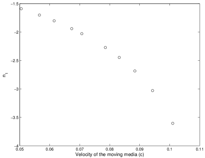
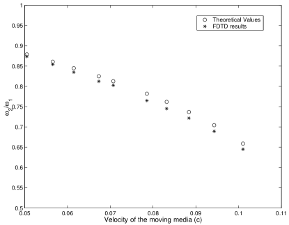
As stated in the introduction, the reverse Doppler effect arises due to the negative index of refraction. The definition of Doppler shift tells us that when a source moves inside the LHM at the initial stationary frame, the abnormal Doppler effect will be observed. Here we consider the system with a LHM moving in the background with another LHM. We choose , , and , which means that the refractive index of the background and the moving media for the incident frequency is and , respectively. Due to Doppler shift for the reflected wave, the refractive index of the background for the reflected wave will change. Figure 3 shows that the refractive index of the background for the reflected wave varies from to (Note that the refractive index of the background for the incident frequency is ). The Doppler shift for the reflected wave from the moving media are shown in Fig. 4, in which the circle and asterisk markers represent the theoretical values (obtained by Eq. (12)) and simulation results (obtained by the FDTD method), respectively. Although the simulation results have a difference with theoretical values, the numerical errors are always less than . The errors may be caused by the numerical calculation of the FDTD method. It can be seen from Fig. 4 that, compared with the results in Figs. 1 and 2 , the Doppler shift for the reflected wave is actually an inverse Doppler effect (redshifted). It is also in agreement with the prediction in the LHM.
IV CONCLUSION
We have studied systemically the Doppler effect for the reflected wave from a moving media and obtained theoretical formula for the Doppler shift in the LHM, which is described by Drude’s dispersive model. We have performed first-principles numerical experiments to examine the Doppler shifts. It has been shown that the results obtained by our theoretical formula are in good agreement with those obtained by numerical experiments. Inverse Doppler effect is confirmed in the left-handed material.
This work was supported by the Swedish Foundation for Strategic Research (SSF) on INGVAR program, the SSF Strategic Research Center in Photonics, and the Swedish Research Council (VR) under project 2003-5501.
References
- (1) Doppler, Abh. Koniglichen Bohmischen Ges. Wiss. 2, 465 (1843).
- (2) C. H. Papas, Theory of electromagnetic wave propagation, McGraw-Hill, 1965.
- (3) M. Einat and E. Jerby, Normal and anomalous Doppler effects in a dielectric-loaded stripline cyclotron-resonance maser oscillator, Phys. Rev. E 56 (1997), 5996-6001.
- (4) E. J. Reed, M. Soljacic, and J. D. Joannopoulos, Reversed doppler effect in photonic crystals, Phys. Rev. Lett. 91 (2003), 133901.
- (5) N. Seddon and T. Bearpark, Observation of the inverse doppler effect, Science 302 (2003), 1537-1540.
- (6) V. G. Veselago, The electrodynamics of substances with simultaneously negative values of and , Sov. Phys. Usp. 10 (1968), 509-514.
- (7) J. B. Pendry, A. J. Holden, W. J. Stewart, and I. Youngs, Extremely low frequency plasmons in metallic mesostructures , Phys. Rev. Lett. 76 (1996), 4773-4776.
- (8) J. B. Pendry, A. J. Holden, D. J. Robbins, and W. J. Stewart, Magnetism from conductors and Enhanced nonlinear phenomena, IEEE Trans. Microwave Theory Tech. 47 (1999), 2075-2084.
- (9) R. A. Shelby, D. R. Smith, and S. Schultz, Experimental verification of a negative index of refraction , Science 292 (2001) 77-79.
- (10) D. R. Smith, D. Schurig, and J. B. Pendry, Negative refraction of modulated electromagnetic waves , Appl. Phys. Lett. 81 (2002), 2713-2715.
- (11) D. R. Smith and D. Schurig, Electromagnetic wave propagation in media with indefinite permittivity and permeability tensors, Phys. Rev. Lett. 90 (2003), 077405.
- (12) S. S. Xiao, L. F. Shen, and S. L. He, A novel directional coupler utilizing a left-handed material, IEEE Photon. Tech. Lett. 16 (2004),171-173.
- (13) T. J. Yen, W. J. Padilla, N. Fang, D. C. Vier, D. R. Smith, J. B. Pendry, D. N. Basov, and X. Zhang, Terahertz magnetic response from artificial materials, Science 303 (2004), 1494-1496.
- (14) L. F. Shen, S. L. He, and S. S. Xiao, Stability and quality factor of a one dimensional subwavelength cavity resonator containing a left handed material, Phys. Rev. B 69 (2004), 115111.
- (15) B. Podolsky and K. S. Kunz, Fundamentals of Electrodynamics, Marcel-Dekker, 1969.
- (16) S. A. Cummer, Simulated causal subwavelength focusing by a negative refractive index slab, Appl. Phys. Lett. 82 (2003) 1503-1505.
- (17) A. Taflove, Computational Electrodynamics: The Finite-Difference Time-Domain Method , Artech House INC, 2000.
- (18) J. P. Berenger, A perfectly matched layer for the absorption of electromagnetic waves, J. Comput. Phys. 114 (1994), 185-200.
- (19) R. W. Ziolkowski and E. Heyman, Wave propagation in media having negative permittivity and permeability, Phys. Rev. E 64 (2001), 056625.
- (20) J. B. Pendry, Negative refraction makes a perfect lens, Phys. Rev. Lett. 85 (2000) 3966-3969.