Bragg-induced orbital angular-momentum mixing in paraxial high-finesse cavities
Abstract
Numerical calculation of vector electromagnetic modes of plano-concave microcavities reveals that the polarization-dependent reflectivity of a flat Bragg mirror can lead to unexpected cavity field distributions for nominally paraxial modes. Even in a rotationally symmetric resonator, certain pairs of orbital angular momenta are necessarily mixed in an excitation-independent way to form doublets. A characteristic mixing angle is identified, which even in the paraxial limit can be designed to have large values. This correction to Gaussian theory is zeroth-order in deviations from paraxiality. We discuss the resulting nonuniform polarization fields. Observation will require small cavities with sufficiently high Q. Possible applications are proposed.
Unconventional beam profiles in free-space paraxial optics have recently received renewed attention, based in large part on the new degrees of freedom made accessible in light-matter interactions when Gaussian beams carry not only spin but orbital angular momentum [1, 2]. To realize the full potential of the resulting rich phenomenology in quantum optical applications [3], it is an important next step to turn from free-space optics to ultrahigh-Q resonators. In this Letter, we study numerically a type of cavity that enables robust and spectrally addressable creation of nearly paraxial light fields with orbital and polarization profiles that are, surprisingly, not predicted by the standard solutions of paraxial theory. We build upon the initial examination in [4, 5].
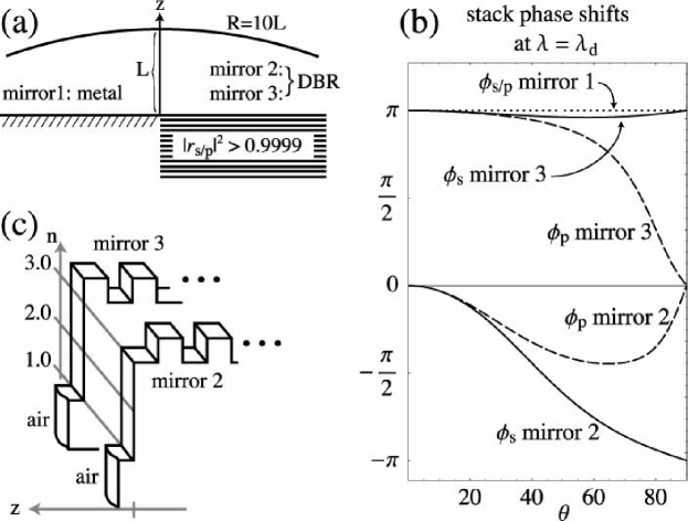
Beams carrying orbital angular momentum require an axially symmetric environment, and hence the cavity in this study has a rotation axis . The dome-shaped resonator is shown in Fig. 1 (a). Standard paraxial wave solutions with definite orbital angular momentum are the Laguerre-Gauss beams (LG). They are labeled by the number of radial nodes, and the orbital angular momentum quantum number : in polar coordinates ,
| (1) |
where is an associated Laguerre polynomial and is the beam waist radius. All beams of the same order form a degenerate manifold in the sense that their longitudinal wave functions are the same for a given frequency . The degree of degeneracy is , including two possible polarization states (e.g. right and left circular, with Jones vectors ); this allows the formation of linear combinations of Laguerre-Gaussians to obtain a wide variety of transverse beam profiles. The cross-sectional electric field within a degenerate LG manifold of order can be expanded as
| (2) |
where (), and is fixed by . This carries over to paraxial resonators where the discrete resonant frequencies are labeled by a longitudinal index and the mode order , and do not depend on and individually.
Our exact numerical solutions reveal that corrections [6] to the standard paraxial resonator theory stated above lead to a splitting of the -multiplets in (2). Compared to the equidistant transverse mode spacing in (governed by the Guoy phase shift), this additional non-paraxial splitting typically occurs on a scale so fine that it can be disregarded in large resonators. However, ultrahigh-finesse microcavities, which are now becoming technologically feasible, will make it necessary to quantify this substructure. The problem is then analogous to zeroth-order degenerate perturbation theory, the small quantity being the paraxiality parameter, .
The question how the degeneracy in (2) is lifted goes beyond paraxial theory. A first guess would be that the new eigenmodes are the LG basis modes where is the spin. All modes are then uniquely labeled by , and . This is indeed what we find when modeling the planar mirror in Fig. 1 (a) as a perfect electric or magnetic conductor ( or ).
In this Letter, however, we focus attention on the case where the planar mirror is a realistic Bragg stack. Then, most of the dome cavity modes are not labeled by a unique , even for the smallest values of the paraxiality parameter . What makes distributed Bragg reflectors (DBR) different is their polarization-dependent plane-wave reflectivity , where s/p denotes linear polarization perpendicular/parallel to the plane of incidence and is the angle of incidence. Figure 1 (b) illustrates that reflection phase shifts with strong dependence may occur even if the DBR design wavelength is chosen so that the modes of interest are at the center of the stop band, where . We have calculated the fully vectorial cavity modes, using a recently developed numerical technique combining a basis function expansion in the dome region with the transfer matrix technique for the DBR [4, 5]. What we describe below can be called DBR-induced, paraxial spin-orbit coupling of light.
The numerical method is not restricted to near-paraxial modes[4], and the results presented here are observed over a wide range of ; but we shall focus on the limit where should constitute a suitable basis in which to express the (transverse) cavity fields. The vectorial modes can be chosen to be eigenfunctions of the total angular momentum around the axis, with integer eigenvalues . If orbital and spin angular momenta and are “good quantum numbers”, then . As illustrated in Table 1 of Ref. [4], specifying and in (2) singles out pairs of , with (unless , in which case only occurs). We shall call these pairs doublets because their paraxial degeneracy is in fact lifted. This is to be distinguished from a remaining reflection-induced exact degeneracy between modes differing only in the sign of . By fixing , the latter degeneracy can be disregarded for our purposes.
The lowest order for which the above doublets exist is , and we consider this case from now on. Both and are transverse basis functions with . If is a good quantum number but and are not, then the transverse parts of the actual , cavity modes (denoted symbolically by , ) will be superpositions
| (3) |
where is a mixing angle: when , the modes are well approximated by pure LG profiles. Among the different mirrors shown in Fig. 1, only the conductor shows in general. The doublet’s resonant frequencies satisfy for , but the mixing angle generally does not vanish in this paraxial limit.
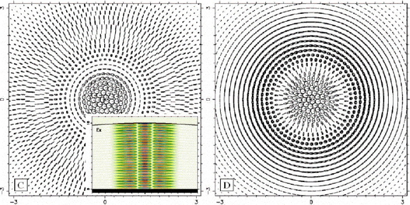
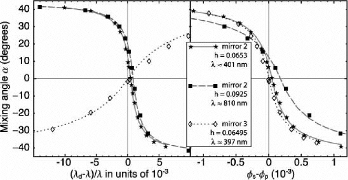
Figure 2 (a) gives the variation of as is changed. The sigmoid shape of the curves means that in a typical cavity, one will find the doublet , at a value of near . This is the furthest from pure LG modes we can get, in spite of the rotational symmetry of the whole cavity. Note that again describes pure LG states, and in going through a total variation by the modes exchange character. This dramatic change occurs over a narrow interval, going through the “unmixed” state at which point the resonance frequencies , exhibit an avoided crossing (not shown).
The non-conservation of orbital and spin angular momentum does not rely on paraxiality: the - field components of a cavity eigenstate with total angular momentum are linear combinations of two opposing circular polarization fields which individually transform under coordinate rotations according to different orbital angular momenta ; modes A and B in (3) are the paraxial realization of this general fact. A Bessel-wave expansion[4] of the mode shows that one of the orbital wave functions can in fact be made to vanish exactly if for the planar mirror. This occurs for pure magnetic or electric conductors. In the DBR cavity, on the other hand, we only have at , cf. Fig. 1 (b). Since even the most paraxial modes contain nonzero in their angular spectrum, one cannot generally factor the field into a fixed polarization vector multiplying a scalar orbital wave function. Within the conventional paraxial approach, where this factorization is performed at the outset, the consequences of a finite at nearly vanishing are lost.
By changing the detuning of the doublet from , we also change the phase difference at any finite angle of incidence . As discussed elsewhere [7], one can identify an “effective” at which to evaluate . Plotting versus this variable in Fig. 2 (b), the universality of the spin-orbit coupling is revealed: the data differ widely in the mirror designs and wavelengths used, but collapse onto very similar curves. The broad appearance of the dotted curve in 2 (a) arises mainly because the reflection phases of mirror 3 are less sensitive to detuning. The data are fit by the function[7], . The offset for attaining circular polarization () accounts for the fact that and are not equal at zero detuning when evaluated at finite . The crossover between has width , and persists in the zeroth-order limit where .
In Figure 3, we illustrate the polarization patterns produced by the spin-orbit coupling. Polarization ellipticity and orientation vary spatially. In particular, the single mode C exhibits circular polarization near the axis but radial linear polarization within its second radial maximum; in mode D, a crossover from circular to azimuthal linear polarization occurs. The m cavity height in this example allows to be resolved despite the finite widths of the modes, which is taken into account in our numerics (cf. the DBR design in Fig. 1, and the data on decay widths in Ref. [4]). Assuming that both mirrors have a power reflectivity in the range , we estimate that the effects shown here should be observable for cavities with paraxiality if the height of the resonator lies in the window . The mode patterns in Fig. 3 are governed by the mixing angle ; Fig. 2 suggests the intriguing possibility of externally controlling by changing the cavity dimensions or Bragg wavelength .
When addressed by laser pulses at and , the doublet modes could interact with one, two, or more asymmetric (polarization-sensitive) quantum dots embedded in the DBR. Thus the mixed modes may allow a new scheme of quantum processing. Cavities of the type studied here can also act as filters or laser emitters of pure or mixed LG beams, useful as “optical tweezers”[2] or as carriers of information[8].
Provided that at least one of the mirrors is a Bragg stack, any stable cavity should exhibit paraxial mixing of orbital angular momenta. Its observability hinges on the ability to distinguish true degeneracies from “quasi”-degeneracies caused by the breakdown of Eq. (2). Our quantitative analysis shows that the necessary requirements can be met by realistic cavities that are being pursued for quantum-optics applications.
We thank Mike Raymer for valuable discussions. This work was supported by NSF Grant ECS-0239332.
References
- [1] M. Padgett, J. Courtial, and L. Allen, Physics Today 57, 35–41 (2004).
- [2] D. G. Grier, Nature 424, 810–816 (2003).
- [3] T. M. Stace, G. J. Milburn, and C. H. W. Barnes, Phys. Rev. B 67, 085,317 (2003).
- [4] D. H. Foster and J. U. Nöckel, Opt. Commun. 234, 351–383 (2004).
- [5] D. H. Foster and J. U. Nöckel, in Resonators and Beam Control VII, A. V. Kudryashov and A. H. Paxton, eds., Vol. 5333 of Proceedings of SPIE, pp. 195–203 (2004).
- [6] V. M. Babic and V. S. Buldyrev, Short-wavelength diffraction theory (Springer Verlag, Berlin, 1972).
- [7] D. H. Foster and J. U. Nöckel, “Coupling of optical Born-Oppenheimer modes in near-paraxial cavities”, in preparation
- [8] E. J. Galvez, P. R. Crawford, H. I. Sztul, M. J. Pysher, P. J. Haglin, and R. E. Williams, Phys. Rev. Lett. 90, 203901 (2003).