Also at ]University of Chicago, Chicago, IL 60637, USA Now at ]Far-tech Inc, San Diego, CA 92121, USA Now at ]Purdue University, West Lafayette, IN 47907, USA
Generation of angular-momentum-dominated
electron beams from a photoinjector
Abstract
Various projects under study require an angular-momentum-dominated electron beam generated by a photoinjector. Some of the proposals directly use the angular-momentum-dominated beams (e.g. electron cooling of heavy ions), while others require the beam to be transformed into a flat beam (e.g. possible electron injectors for light sources and linear colliders). In this paper, we report our experimental study of an angular-momentum-dominated beam produced in a photoinjector, addressing the dependencies of angular momentum on initial conditions. We also briefly discuss the removal of angular momentum. The results of the experiment, carried out at the Fermilab/NICADD Photoinjector Laboratory, are found to be in good agreement with theoretical and numerical models.
pacs:
29.27.-a, 41.85.-p, 41.75.FrI Introduction
Angular-momentum-dominated electron beams generated by photoinjectors have direct applications in several accelerator proposals presently under consideration, either in the field of high-energy colliders or accelerator-based light sources. In Reference benzvi , an angular-momentum-dominated, or “magnetized”, beam is proposed to be accelerated to MeV and used for electron beam cooling budker ; derbenevmag of ion beams in the relativistic heavy ion collider (RHIC). In such a scheme, the electron beam propagates together with the ion beam at the same velocity. Collisions of ions with electrons lead to a transfer of thermal motion from the ion to the electron beam. As the two beams co-propagate, the electron-ion effective interaction length is increased due to the helical trajectory of the electron in the magnetic field, thereby improving the cooling efficiency. The cooling rate is then mainly determined by the longitudinal momentum spread of the electron beam, which can be made much smaller than the transverse one. Reference brinkmann concerns the photoinjector production of flat beams, i.e. a beam with high transverse emittance ratio. The technique consists of manipulating an angular-momentum-dominated beam produced by a photoinjector using the linear transformation described in Reference derbenev . The latter linear transformation removes the angular momentum and results in a flat beam. In the context of linear collider proposals, where a flat beam at the interaction point is needed to reduce beamstrahlung yokoya , the development of a flat-beam electron source is an attractive idea since it could simplify or eliminate the need for an electron damping ring. The flat beam technique is also proposed for generation of ultrashort X-ray pulses by making use of the smaller dimension of the flat beam lux , and also in enhancing beam-surface interaction in a Smith-Purcell radiator kjk2 or in an image charge undulator smithpurcell . A proof-of-principle experiment conducted at the Fermilab/NICADD Photoinjector Laboratory (FNPL)111NICADD is an acronym for Northern Illinois Center for Accelerator and Detector Development. has demonstrated the flat beam production edwards ; edwardspac01 , where an emittance ratio of was reported.
In this paper we report on recent results pertaining to the experimental investigation of some properties of an angular-momentum-dominated beam. We also briefly address the removal of angular momentum and the subsequent generation of a flat beam. Producing flat beams is our primary motivation for the present studies.
In Section II we briefly summarize theoretical aspects of the photoinjector production of angular-momentum-dominated beams. In Section III we describe the experimental set-up of FNPL. Sections IV and V are dedicated to experimental results and their comparisons to theory and numerical simulations. Our conclusions appear in Section VI.
II theoretical background
In this section we assume the beam and external focusing forces to be cylindrically symmetric. The cylindrical symmetry implies the conservation of the canonical angular momentum of each electron. In an axial magneto static field , the canonical angular momentum of an electron, , in circular cylindrical coordinates is Reiser
| (1) |
where is the Lorentz factor, the time derivative of , and are respectively the electron rest mass and charge.
The average canonical angular momentum of the electrons, , is obtained by averaging Eq. (1) over the beam distribution. At the photocathode location, we have and
| (2) |
where is the transverse root-mean-square (rms) beam size on the photocathode, is the axial magnetic field on the photocathode.
Outside the solenoidal field region, where vanishes, an electron acquires mechanical angular momentum due to the torque exerted on it in the transition region. Since , the second term of Eq. (1) vanishes and the canonical angular momentum is given by the first term of Eq. (1), which is the mechanical angular momentum. It is convenient to normalize with the axial momentum , and introduce the quantity given by
| (3) |
where .
The beam angular momentum can be removed by means of a properly designed skew quadrupole section burov ; brinkmann2 ; BND-PRE and the beam is transformed into a flat beam (see section V). The flat beam transverse emittances after the skew quadrupole section, , are given by BND-PRE ; kjk :
| (4) |
Here is the uncorrelated transverse emittance prior to the skew quadrupole section. Note that the four dimensional emittance is conserved since .
The evolution of the transverse rms beam size of a relativistic electron bunch in a drift is given by the envelope equation reiserenv
| (5) |
where is the transverse rms size, is the generalized perveance, is the absolute value of the instantaneous beam current and is the Alfvén current for electrons ( kA). The second, third and fourth terms respectively represent the effects due to space charge, emittance and the angular momentum. For low energy beam, the space charge term is important. However, for the typical operating conditions considered in this paper, e.g., , bunch charge nC, rms beam duration ps, mm yesBD1 , mm mrad lidia , mm mrad, the fourth term Eq. 5 is much greater than the second and the third term. Such a beam is said to be angular momentum dominated.
III experimental setup
The experimental production and characterization of angular-momentum-dominated electron beams were carried out at FNPL.
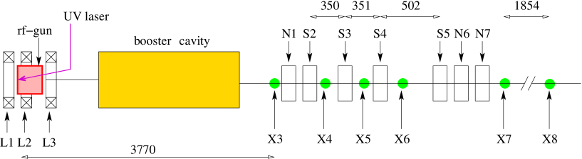
The photoinjector incorporates a photoemission source consisting of a cell cavity operating at 1.3 GHz, the so-called radio frequency (rf) gun. An ultraviolet (UV) laser impinges a cesium telluride photocathode located on the back plate of the rf gun half cell. The thereby photoemitted electron bunch exits from the rf-gun at 4 MeV/c and is immediately injected into a TESLA-type superconducting cavity teslacav (henceforth referred to as the booster cavity). The bunch momentum downstream of the booster cavity is approximately 16 MeV/c when the cavity is operated to yield the maximum energy gain. The typical operating conditions of the main subsystems of the photoinjector are gathered in Table 1, and a block diagram of the facility is depicted in Fig. 1.
The transverse size of the UV drive-laser at the photocathode is set by a remotely controllable iris. The laser temporal profile is a Gaussian distribution with rms duration of 3.5 ps.
The rf gun is surrounded by three solenoidal magnetic lenses independently powered. This allows proper focusing of the electron bunch while maintaining the desired magnetic field on the photocathode.
Downstream of the booster cavity, the beamline includes a round-to-flat-beam (RTFB) transformer, consisting of four skew quadrupoles, that can be used to remove the mechanical angular momentum.
Several optical transition radiation (OTR) or fluorescent (YaG-based) screens serve as diagnostics to measure the beam’s transverse density at various locations in the beamline. Transverse emittances can also be measured based on the multislit Lejeune ; PP , or quadrupole scan techniques Wiedemann . The multislit mask used for emittance measurements consists of a 6-mm-thick tungsten mask with 48 m-wide slits spaced 1 mm apart.
| parameter | value | units |
|---|---|---|
| laser injection phase | 25 5 | rf-deg |
| laser radius on cathode | [0.6, 1.6] 0.05 | mm |
| laser pulse duration | 3.5 0.5 | ps |
| bunch charge | [0.2, 1.6] | nC |
| on cathode | 35 0.2 | MV/m |
| on cathode | [200, 1000] | Gauss |
| booster cavity acc. gradient | 12 | MV/m |
IV Measurements of Canonical Angular Momentum
We now turn to the basic properties of the canonical angular momentum. We especially investigate the conversion of the canonical angular momentum of the photo-emitted electron bunch into mechanical angular momentum downstream of the booster cavity.
The canonical angular momentum at the photocathode surface is obtained from Eq. (2). Given the experimental settings of the solenoidal lens currents, the magnetic field, , is inferred via simulations using the Poisson lanl program, which is bench-marked against calibration of the solenoidal lenses JPCthesis . The value of used in Eq. (2) is directly measured from an image of the UV laser on a “virtual photocathode”. The virtual photocathode is a calibrated UV-sensitive screen, located outside of the vacuum chamber, being a one-to-one optical image of the photocathode.
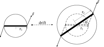
To elaborate the method used to measure the mechanical angular momentum downstream of the booster cavity, we consider an electron in a magnetic-field-free region at longitudinal location with transverse radial vector ( stands for the -axis unit vector). After propagating through a drift space, the electron reaches at location . Let be the angle between the two aforementioned radial vectors ( is henceforth referred to as “shearing angle”; see Fig. 2). The mechanical angular momentum of the electron, , is given by:
| (6) |
By introducing , where is the vertical component of the momentum, and noting that is a constant in a drift space for an angular-momentum-dominated beam, we see that the change in vertical coordinate is (see Fig. 2). Hence Eq. (6) can be rewritten in the convenient form
| (7) |
For a cylindrically symmetric laminar beam with rms transverse beam sizes and at respective locations and along the beamline, the averaged mechanical angular momentum can then be calculated via
| (8) |
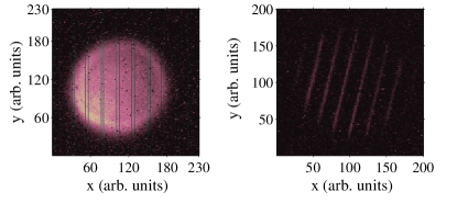
Thus the measurements of rms beam sizes at locations and along with the corresponding shearing angle provide all the necessary information for calculating the mechanical angular momentum. Experimentally, the shearing angle is obtained by inserting at location a multislit mask and measuring the corresponding shearing angle of the beamlets at the location ; see Fig. 3. For the mechanical angular momentum measurement reported here we use the diagnostic stations X3 and X6 (see Fig. 1). The X3 diagnostic station includes an OTR screen and two insertable multislit masks (with vertical and horizontal slits). The station X6 is only equipped with an OTR screen.
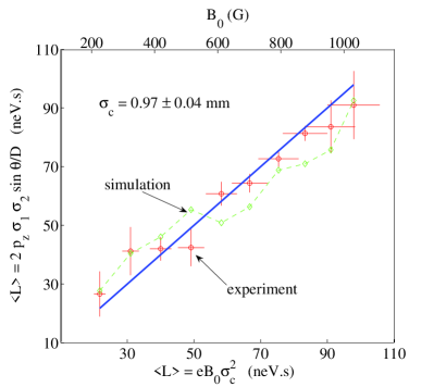
A set of measurements of mechanical angular momentum versus was reported in Ref. YESPAC2003 . In the present Paper, such measurements are performed by varying over a wider range ( Gauss for a bunch charge of nC; see details in Ref. yesBD1 ). The measurement technique discussed in the previous paragraph was also numerically tested for each experimental data point. In Fig. 4 we compare the measured mechanical angular momentum from Eq. (8) with the canonical angular momentum calculated from Eq. (2), given the . The measured values include both experimental data and simulated values, i.e., values that have been retrieved after simulating the measurement technique numerically with the particle tracking program Astra astra . The uncertainties in the measurement of angular momentum are obtained via error propagation from the direct measurements of rms beam sizes and the “shearing angle”.
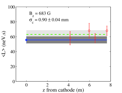
Conservation of canonical angular momentum is demonstrated in Fig. 5, where the angular momentum was measured at different locations along the beamline. In these measurements all quadrupoles are turned off so that the beam propagated in a drift space.
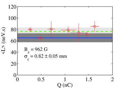
The dependence of mechanical angular momentum on the charge was also explored. In this experiment, the laser spot size was set to mm, and the laser intensity was varied via a wave-plate attenuator located in the UV laser path. The results, shown in Fig. 6(a), indicate the mechanical angular momentum, for our set of operating parameters, is charge-independent, confirming our assumption that the beam dynamics is angular-momentum-dominated in the range explored here.
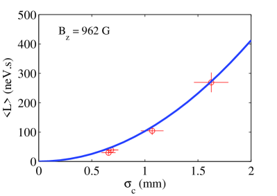
Finally the dependence of canonical angular momentum versus was investigated. The laser intensity was held constant and was identical to the previous experiment ( G). The charge density in the bunch is therefore kept constant. The measurements [see Fig. 6(b)] support the expected quadratic dependence of the angular momentum on indicated in Eq. (2).
The measured dependencies of canonical angular momentum on the different parameters are all in good agreement with theoretical expectations. Such an agreement gives us some confidence on our ability to control the angular momentum of the incoming beam upstream of the RTFB section.
V removal of angular momentum and flat-beam generation
To remove angular momentum, it is necessary to apply a torque on the beam. A quadrupole can exert a net torque only on an incoming asymmetric beam. Thus more than one quadrupole is needed to remove the angular momentum of an cylindrically symmetric incoming beam. A first quadrupole followed by a drift space will introduce asymmetry in the - space, while the other quadrupoles downstream are properly tuned to apply a total net torque such that the angular momentum is removed at the exit of the quadrupole section. For the series of measurements and simulations presented in this section, a set of three skew quadrupoles (S2, S3, S5 in Fig. 1) are used to remove the angular momentum and generate a flat beam.
Given the photoinjector parameters, numerical simulations of the beamline (from the photocathode up to the entrance of the RTFB transformer) are performed using Astra. The four-dimensional phase-space coordinates are propagated downstream of the transformer using a linear transfer matrix. The initial values of the skew quadrupole strengths are those derived, under the thin-lens approximation, in Reference flat2 . They are then optimized, using a least-square technique, to minimize the - coupling terms of the beam matrix at the exit of the transformer. The final optimized quadrupole strengths are used for subsequent Astra simulation of the beam dynamics through the RTFB transformer.
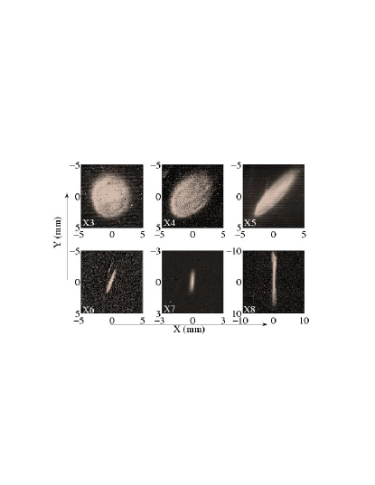
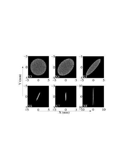
Further empirical optimization around the predicted values is generally needed to insure the angular momentum is totally removed, as inferred by observation of the - coupling at several locations downstream of the RTFB section. Evolution of transverse density throughout the RTFB section is in good agreement with expectations from simulations, as shown in Fig. 7. Each of the top six photos is a superposition of 5 bunches with charge of 0.55 0.10 nC. In the sequence of measurements and simulations presented there, the incoming round beam (X3) is transformed into a flat beam characterized by the large asymmetry (X7 and X8). The mechanical angular momentum is removed: there is no noticeable shearing as the beam propagates from X7 to X8.
VI conclusion
We have experimentally explored some parametric dependencies of angular momentum for an angular-momentum-dominated electron beam produced in a photoinjector. The results obtained are in good agreement with theoretical expectations, giving us some confidence in our understanding of the angular-momentum-dominated beam.
VII acknowledgements
We wish to express our gratitude to H. Edwards for her many valuable suggestions and stimulating discussions during the experiment, and for her constant support. We are grateful to D. Edwards for his comments on the manuscript and his leadership in the first flat beam demonstration experiment. We are indebted to C. Bohn of Northern Illinois University for carefully reading and commenting on the manuscript. We thank M. Hüning, K. Desler for their help in the operation, and W. Muranyi, M. Heinz, M. Rauchmiller, R. Padilla, P. Prieto and B. Degraff for their excellent technical support. This work was supported by Universities Research Association Inc. under contract DE-AC02-76CH00300 with the U.S. Department of Energy, and by NICADD.
References
- (1) I. Ben-Zvi et al., in Proceedings of the 2003 Particle Accelerator Conference, Portland, Oregon (IEEE, Piscataway, NJ, 2003), pp. 39-41.
- (2) Ya. Derbenev et al., Fizika Plasmy 4, 492-500 (1978).
- (3) G. I. Budker et al., IEEE trans. Nucl. Sci. NS-22, 2093-2097 (1975).
- (4) R. Brinkmann, Y. Derbenev and K. Flöttmann, Phys. Rev. ST Accel. Beams 4, 053501 (2001).
- (5) Ya. Derbenev, University of Michigan Report No. UM-HE-98-04, 1998.
- (6) K. Yokoya and P. Chen, in Proceedings of the 1989 Particle Accelerator Conference, Chicago, IL (IEEE, New York, NY, 1989), pp. 1438-1440.
- (7) J. Corlett et. al, in Proceedings of the 2002 European Particle Accelerator Conference, Paris, France (EPS-IGA and CERN, Geneva, 2002), pp. 668-670.
- (8) K.-J. Kim, private communications; C. Bohn et. al, unpublished, available at http://nicadd.niu.edu/presentations/BohnFNPLspeoi.doc.
- (9) Y. Zhang, Ya. Derbenev, J. Boyce and R. Li, in Proceedings of the 2003 Particle Accelerator Conference, Portland, Oregon (IEEE, Piscataway, NJ, 2003), pp. 941-943.
- (10) D. Edwards et al., in Proceedings of the XX International Linac Conference, Monterey, CA, pp. 122-124 (2000).
- (11) D. Edwards et al., in Proceedings of the 2001 Particle Accelerator Conference, Chicago, IL (IEEE, Piscataway, NJ, 2001), pp. 73-75.
- (12) See for example, M. Reiser, Theory and Design of Charged Particle Beams (John Wiley & Sons, inc., 1994), pp. 33-35.
- (13) A. Burov and V. Danilov, FNAL Report No. TM-2043, 1998.
- (14) R. Brinkmann, Y. Derbenev and K. Flöttmann, DESY Report No. TESLA 99-09, 1999.
- (15) A. Burov, S. Nagaitsev and Ya. Derbenev, Phys. Rev. E 66, 016503 (2002).
- (16) K.-J. Kim, Phys. Rev. ST Accel. Beams 6, 104002 (2003).
- (17) M. Reiser, Theory and Design of Charged Particle Beams (John Wiley & Sons, inc., 1994). We start from Eq. (5.218), the second term vanishes for a drift space. Adding the canonical angular momentum term, which resembles the emittance term (see Eq. (4.80)), we obtain Eq. (5) of the present paper. See also S. Lidia, Lawrence Berkeley National Laboratory Report No. 56558, 2004 (to be published).
- (18) Y.-E Sun and P. Piot, Fermilab Beams Document, Beams-doc-1254-v1, 2004 (unpublished). Available at http://beamdocs.fnal.gov.
- (19) S. Lidia, in Proceedings of the 2003 Particle Accelerator Conference, Portland, Oregon (IEEE, Piscataway, NJ, 2003), pp. 2089-2091.
- (20) B. Aune et al., Phys. Rev. ST Accel. Beams 3, 092001 (2000).
- (21) C. Lejeune and J. Aubert, Adv. Electron. Electron Phys., Suppl. 13A, 159 (1980).
- (22) P. Piot, G. A. Krafft, R. Li and J. Song, Proceedings of the XIX International Linac Conference, Chicago, IL, pp. 684-688 (1998).
- (23) H. Wiedemann, Particle Accelerator Physics: Basic Principles and Linear Beam Dynamics (Springer-Verlag, 1999), pp. 157-158.
- (24) J. H. Billen and L. M. Young, in Proceedings of the 1993 Particle Accelerator Conference, Washington DC (IEEE, Piscataway, NJ, 1993), pp. 790-792.
- (25) J.-P. Carneiro, Ph.D. thesis, Université de Paris - Sud, 2001.
- (26) Y.-E Sun et al., in Proceedings of the 2003 Particle Accelerator Conference, Portland, Oregon (IEEE, Piscataway, NJ, 2003), pp. 2682-2684.
- (27) K. Flöttmann, “Astra: A Space Charge Tracking Algorithm”, user manual available at http://www.desy.de/mpyflo/Astra_dokumentation.
- (28) E. Thrane et al., in Proceedings of the XXI International Linac Conference, Gyeongju, Korea (Pohang Accelerator Laboratory, Pohang, Korea, 2002), pp. 308-310.