Ion Resonance Instability in the ELTRAP electron plasma
Abstract
A small fraction of ions can destabilize the diocotron mode (off axis rotation) of an electron plasma confined in a Malmberg-Penning trap. In this paper a set of experimental measurements performed in the ELTRAP device on the ions induced diocotron instability is presented. In particular, the dependence of the instability on the electron energy has been analyzed, by heating the plasma with a RF burst or by injecting into the trap electrons with different energies. A simple experimental technique to limit the instability is also described.
I Introduction
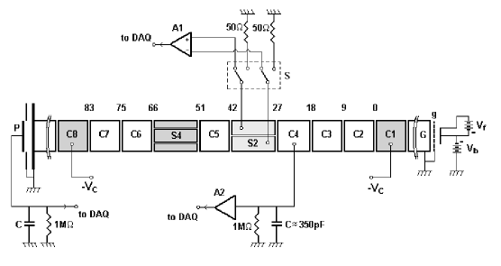
A pure electron plasma can be confined for a long time (up to several minutes) in a Malmberg-Penning trap by means of static magnetic and electric fields Amoretti et al. (2003). The plasma is trapped within a stack of hollow conducting cylinders (see Fig. 1), kept in UHV conditions ( nTorr); negative voltages ( V) applied on two of the cylinders trap the electrons axially, and a static and uniform magnetic field keeps the plasma in rotation around the cylindrical axis, thus providing the radial confinement: the inward directed Lorentz force balances the electrostatic repulsion between the electronsi, and the centrifugal force. The device usually operates by repeating many cycles of injection-hold-dump of the plasma. The electrons are generated by a thermionic cathode and injected into the trap by a small accelerating voltage applied on a grid. Acting on the source parameters the initial particle energy distribution can easily be changed. During the hold phase, the plasma dynamics is studied by means of the analysis of the induced charge signals detected at the walls of the confining cylinders; at the end of the hold phase an axially integrated density distribution is obtained by accelerating the particles towards a phosphor screen (kept at a positive potential of few kV), and detecting the emitted light by means of a high sensitivity CCD camera.
The confined plasma evolves through an initial turbulent state, characterized by the non-linear interaction of several small and intense vortices which dissipate on the collisional time scale ( ms) towards a global equilibrium state, characterized by a flat radial density profile and a constant, shear-free bulk rotation (rigid rotor equilibrium). If the confinement conditions were ideal (zero residual gas pressure, no field errors) the electron plasma could be confined forever. On the other hand, electron-neutral collisions, small alignement errors of the cylinders and magnetic fields irregularities act on the plasma as external drags, causing radial expansion and loss of particles at the walls. In addition, the confinement of the plasma is influenced by the plasma instabilies (in particular the diocotron instability), which drive the column against the walls.
II The diocotron mode and its diagnostic
In the injection phase, the electron column is usually loaded with a small radial offset : such an initial displacement determines the formation of image charges, and the relevant electric fields add a new drift motion to the plasma. This off-axis rotation, known in the literature as diocotron mode, has a frequency , where is the linear charge density of the plasma, is the magnetic field strength and is the inner radius of the cylinders. The frequency and the amplitude of the mode are diagnosed analyzing the induced charge signals on the electrodes. These electrostatic probes give also informations on high order diocotron waves on the plasma surface, and can also be used as perturbation launchers. The electrostatic signals are conditioned, digitally filtered and Fourier transformed: the time-varying spectra show a set of peaks related to the plasma rotation. In Fig. 2 the equivalent external circuit is shown: the induced charge is equivalent to a sinusoidal current generator (at frequency ), connected to an external impedance and an amplification circuit.
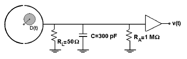
The stationary response of the circuit is given by the following Fourier series,
is equivalent resistance of and , the line capacitance (see Fig. 2), is the length of the probe and its angular aperture. The radial offset can then be expressed as a function of experimentally known quantities
where . This approximated formula, valid for , allows to infer the plasma offset , scanning the frequency and the amplitude data of the signals on the confining conducting cylinders. This diagnostic is non destructive and very fast. The external load is selected in order to avoid resistive effects White et al. (1982).
III The diocotron instability
The diocotron mode is unstable on the time scale of seconds as shown in Fig. 3: the plasma offset increases linearly with time, until the column touches the wall and loses particles. The frequency starts decreasing at the instant of amplitude saturation (see Fig. 4).


The diocotron instability is caused by the presence of a small ion population Perrung et al. (1993): the ions are created at thermal energies by electron-neutral collisions, and then flow out of the system in a fraction of ms. A resonant interaction between the transverse motion of the ions and the low-frequency plasma diocotron rotation makes the mode unstable. A -independent 2D model which considers confined ions predicts an exponential growth Levy et al. (1969); a more recent 2D theory, which takes into account the “transient” behavior of the ions Fajans (1993), predicts a linear growth for the mode amplitude. The experiments performed in the ELTRAP device qualitatively agree with the model of transient ions.
IV Triggering the ion-resonance instability
The instability starts from a small offset when the plasma is trapped. The growth rate is negligible in the case of a low residual gas pressure and at low electron temperature ( eV, nTorr) because in these conditions the ionization rate of the background gas is very small. At a fixed neutral gas pressure the instability can be triggered by acting on the confinement of the ions and/or by changing the energy of the electrons, which can be varied at the injection or during the hold phase with a RF burst.
IV.1 Effect of ions trapping
A couple of confining cylinders has been positively biased, thus creating a potential well for the positive charges. The ions accumulate in the system and determine a sharp increase in the mode growth rate, as shown in Fig. 5.

IV.2 Effect of the electron injection energy
The initial energy of the electrons can be changed acting on the source parameters (in particular the voltage drop, , between the extraction grid and the cathode). A more energetic electron plasma can easily ionize the residual neutral gas, causing an increase in the growth rate of the mode. This effect is shown in Fig. 6: the curves are parametrized with the source bias , which is related to the energy of the electrons at the injection time.

The growth rate increases exponentially with the energy of the electrons, see Fig. 7.

IV.3 Effect of a non-adiabatic plasma injection
The injection phase of the plasma ends with the application of a negative potential on the confining cylinder on the source side which separates the plasma from the cathode. This operation can be done adiabatically, with a slow voltage ramp, or in a very fast way (on the time scale of the electrons bounce motion) exploting the high slew rate of the external voltage generator. At a fixed (low) source bias, a fast ramp up time can increase the electron initial energy, triggering the diocotron instability as shown in Fig. 8.

IV.4 Effect of RF heating
The ionisation rate can be changed during the hold time acting on the plasma temperature. The electrons have been heated with a standard RF technique Kabantsev and Driscoll . The frequency of the RF signal is chosen in order to be resonant with the electron axial bounce motion. A single RF burst, with a duration of few tens of milliseconds and a frequency of a few MHz, increases the electron energy and by consequence the ionization rate. The effect of the plasma heating on the mode growth rate is shown in Fig. 9.

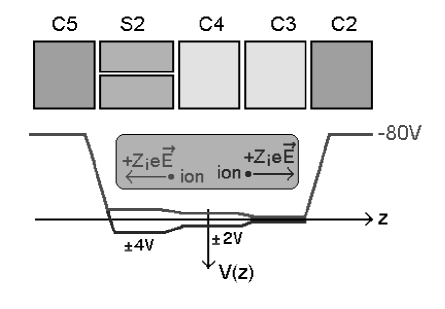
V Control of the instability
The ion resonance instability has been limited removing the ions from the trap just after they have been . This task has been accomplished by a small static electric field (see Fig. 10) superimposed on the confining potential well. The field is created by low voltages applied on inner electrodes. These electrodes are grounded in the standard configuration of the trap. The amplitude of the field is chosen in order to not alter significantly the potential well of the electrons.


In Fig. 11 and Fig. 12 the effect of this technique on the time evolution of the mode amplitude is shown. In particular, it can be observed that the repeated application of the ion removing field can easily double the lifetime of the plasma.
VI Conclusions
The ion resonance diocotron instability has been experimentally investigated in the Malmberg-Penning trap ELTRAP. The instability is characterized by a linear growth of the amplitude, according to the model described in Ref. Fajans (1993). The instability has been triggered by increasing the number of ions in the system, trapping them for a longer time or increasing the ionization rate. The instability has been controlled by the application of proper ions removing fields which eject the ions from the trap just after they have been produced, thus increasing the plasma lifetime.
References
- Amoretti et al. (2003) M. Amoretti, G. Bettega, F. Cavaliere, M. Cavenago, F. D. Luca, R. Pozzoli, and M. Romé, Rev. Sci. Instrum. 74, 3991 (2003).
- White et al. (1982) W. D. White, J. H. Malmberg, and C. F. Driscoll, Phys. Rev. Lett. 49, 25 (1982).
- Perrung et al. (1993) A. Perrung, J. Notte, and J. Fajans, Phys. Rev. Lett. 70, 295 (1993).
- Levy et al. (1969) R. H. Levy, J. D. Daugherty, and O. Bunemann, Phys. Fluids 16, 2616 (1969).
- Fajans (1993) J. Fajans, Phys. Fluids B 5, 3807 (1993).
- (6) A. A. Kabantsev and C. F. Driscoll, AIP Conference Proceedings 692, ed. by M. Schauer, T. Mitchell and R. Nebel (Melville, New York, 2003), p. 61.