Laser acceleration of ion bunches at the front surface of overdense plasmas
Abstract
The acceleration of ions in the interaction of high intensity laser pulses with overdense plasmas is investigated with particle-in-cell simulations. For circular polarization of the laser pulses, high-density ion bunches moving into the plasma are generated at the laser-plasma interaction surface. A simple analytical model accounts for the numerical observations and provides scaling laws for the ion bunch energy and generation time as a function of pulse intensity and plasma density.
pacs:
52.38.-r, 52.38.Kd, 52.50.Jm, 52.65.RrThe study of the interactions between ultra-intense laser pulses and plasmas has proved to be a very rich soil where technological progress and fundamental physics meet each other. Particularly intriguing is the concept of laser-plasma based ion acceleration. From astrophysics astro , to medical hadrontherapy medics , from proton radiography radiography , to nuclear physics nuclear , from proton imaging techniques imaging , to nuclear fusion fusion , the problem of accelerating and manipulating charged particles with laser-plasma interactions offers a series of challenges ranging from fundamental to applied physics, thus a clear understanding of the basic mechanisms is mandatory. Several recent experiments have reported the emission of energetic ions from solid targets exp . It is still a matter of debate whether the ions are mainly accelerated at the rear surface of the target (by the field generated by fast electrons escaping in vacuum mora-betti ) or at the front surface involving phenomena such as acceleration by a collisionless electrostatic shock denavit ; silva ; wei , by a solitary wave zhidkov or by ion trapping in a propagating double layer shorokhov .
In this work we elucidate an even more basic process of ion acceleration in cold plasmas, purely related to the formation of an electrostatic field due to the action of the laser ponderomotive force on the electrons and, consequently, on the ions via space charge displacement. This investigation shows both the necessity of a kinetic description of this process and the fundamental role played by the laser light polarization by showing the differences between circular and linear one. It will be shown by particle-in-cell (PIC) simulations that circularly polarized light gives rise to a “pulsed”acceleration and produces ion bunches directed into the target. A simple analytical model is used to explain the acceleration dynamics and for the deduction of scaling laws that relate the interaction parameters to the energy acquired by the ions. With respect to other concepts for laser ion acceleration, the present mechanism with circularly polarized light leads to very high densities in the bunches, as might be of interest for problems of compression and acceleration of high–density matter.
We consider a laser pulse impinging on a cold, step–boundary, overdense plasma with , where is the initial electron density, is the critical density for a laser with carrier frequency , is the plasma frequency and , are the electron mass and charge. The laser field amplitude will be given in units of the dimensionless parameter . In the PIC simulations, the resolution is high enough to resolve low density regions, sharp gradients and the dynamics of both electrons and ions by taking at least 20 particles per cell at and a spatial resolution better than where . For reference, in all simulations shown the target boundary is located at and the laser impinges on it at .

The essential features of the generation of ion bunches can be seen from one–dimensional (1D) simulations. The laser pulse is circularly polarized, incident from the left side and propagating along the axis; its amplitude rises for (where is the laser period) up to the value and then remains constant. The plasma has a slab profile with and thickness . Electrons and ions are assumed to be cold, , and ion charge and mass number are , .
Fig. 1 shows the ion density profiles and () phase space projections at different times. At a sharp peak of the ion density reaching up to seven times the initial value is shown which moves inwards the plasma with an average velocity of about leaving behind a low–density shelf with velocity linearly decreasing. At , after the density at the peak has reached the maximum value of about and the velocity has reached the value of , a second density peak has appeared on the right of the first peak and moves into the plasma at the speed of about with the () distribution now clearly a two–valued function of .
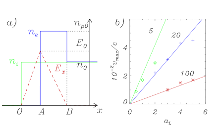
A simple model for this ion bunch generation can be inferred. When the laser pulse impinges on the plasma surface, electrons are quickly pushed inward by the ponderomotive force, i.e. the steady part of the force. (Notice that the oscillating part of the force is zero for circular polarization; this is the reason why, as shown below, the interaction regime is completely different for linear polarization). The electrons pile up leaving behind a charge depletion layer and giving rise to an electrostatic field back–holding them. We assume that they quickly reach an equilibrium position where balances the ponderomotive force exactly. Let us take for simplicity a linear profile of both in the depletion layer ( for ) and in the compression region ( for ), which implies a uniform electron density in this region, see Fig. 2. The parameters , , and are related by the equations (due to Poisson equation), (due to global charge conservation), and (due to the balance between the total radiation and electrostatic pressures).
The electrostatic field on the ions starting at initial positions is a constant over the trajectories of the ions, , and increases with . Thus, these ions will never reach those with , the ion density will decrease and a ion “shelf” will be formed, the field on the leftmost ion layer being zero. As for the ions with initial position in the compression region , assuming that the electrostatic field is a function of for these ions too is consistent with the assumption that the electrons follow a quasi–equilibrium dynamics and the ponderomotive force equals the electrostatic field at any time, the total pressure being always . Being the electrostatic field a linear function of , all ions will reach the point at the same time and the ion density will assume an infinite value there, i.e. the hydrodynamic description breaks down. The ion bunch is thus due to accelerated ions that cross the point and are injected into the unperturbed plasma region, where they can move ballistically provided that the charge unbalance is neutralized by electrons accompanying the bunch. The total number of accelerated ions per unit surface is .
Note that the model assumes the point , where the field vanishes, not to move during compression, and predicts ions to have a a flat–top velocity distribution extending between and and thus the density to be uniform in the region behind the ion front. Actually, since for the evanescence length we expect , during the compression of the ion fluid the field will tend to penetrate deeper into the plasma keeping the field at the surface and the total electrostatic pressure constant. Thus, ions beyond point will be accelerated by a field decreasing in time and will get to the breaking point later. This effect causes the ion bunch to be more localized both in coordinate and velocity space.
Our model thus gives a scenario in qualitative agreement with the numerical observations and also provides quantitative estimates and scaling laws. Denoting as the initial position of an ion with mass and charge in the compression region, (), the force acting on this ion is given by . Thus, The velocity of an initially immobile ion is and the position is . The “breaking” time at which all ions reach point is . The maximum velocity is thus , being the average ion velocity, i.e. the velocity of the laser front. By relating the model parameters to the laser intensity and plasma density we obtain
| (1) |
where has been assumed. The predicted velocity scaling has been tested via numerical simulations, yielding a rather good agreement with the model, see Fig. 2. For instance, for the parameters of Fig. 1 the model predicts and ; in the simulation the breaking of the ion front occurs at which, taking into account the pulse rise time of , is in fair agreement with the model prediction.
At the “breaking” of the ion profile with the formation of the bunch, the equilibrium between the electrostatic and the ponderomotive forces on electrons is lost and, if the laser pulse is not over, electrons rearrange themselves to provide a new equilibrium. The process of bunch formation might then restart although with different initial conditions, so that the simple model is not adequate anymore for quantitative predictions. In Fig. 1 a second wide bunch actually appears at and then propagates into the plasma. At later times, bunches with shorter duration are generated at a higher rate.

For potential applications, it is interesting to study the possibility to produce a single bunch from a thin solid target. Results for the case of an , target with a thickness and a short pulse with intensity are shown in Fig. 3. The temporal envelope for the field is given by with . A single bunch of ions with velocity is produced at and leaves the target from the back side. The ion bunch charge is completely neutralized by electrons both inside and outside the target.
Collisional ion stopping (not included in the PIC code) should not affect ion bunch generation strongly for thin, low– targets. In fact, taking for the example of Fig.3 , so that , the stopping power in the cold plasma given by the Bohr formula atzeni is for ions with and charge , and the stopping length is thus , lower than the target thickness in the example if . For lower densities, typical of preformed plasmas or, e.g., foam targets, collisional ion stopping is even less important. Collective ion stopping in the plasma is included in the PIC simulation, and is found not to affect ion transport in the regimes addressed by our simulations.
The mechanism of ion bunch formation outlined above works cleanly for circular laser polarization. For linear polarization the oscillating part of the force causes strong electron heating (up to MeV energies) which changes the regime of ion acceleration qualitatively. Fig. 3 shows results from a simulation with parameters identical to Fig. 1 but the laser polarization that was changed to linear. No clear propagating ion bunch as that of Fig. 1 is observed. The hot electrons form a Debye sheath leading to ion acceleration towards vacuum at the back surface as soon as they reach it while a few ions are also accelerated from the front surface towards vacuum in a similar way (Fig. 3). Near the laser pulse front, the phase space structures look similar to those generated by the shock acceleration investigated in Ref.silva at higher intensity. For the present parameters, sheath acceleration dominates at the time shown. In contrast, for circular polarization, it is found that most of the electrons are heated up to energies of a few keV behind the ion bunch and at the laser–plasma interaction surface.
Notice that in the case of shock acceleration (see e.g. Ref.silva ) the laser pulse acting as a piston drives a shock wave into the plasma which reflects the ions thus accelerated up to velocities twice the shock speed. In the present case the fastest ions have twice the piston velocity, i.e. the velocity of the laser reflection front at the breaking time, and they come from behind the front. It is also worth to notice that the present mechanism of ion bunch formation is of electrostatic and kinetic nature while a purely hydrodynamic description is not adequate.
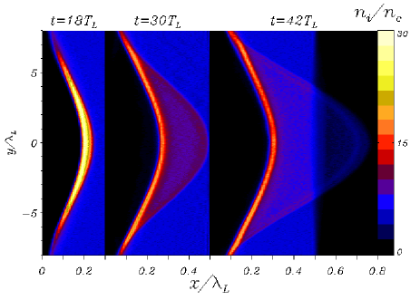
We performed 2D simulations to show that the mechanism for bunch formation is also at play in more than one dimension, and in particular in the case of a laser pulse with a finite transverse width that bends the plasma surface (hole boring). Fig.4 shows results for a case where the laser pulse has a Gaussian intensity profile in the transverse () direction with halfwidth , duration , and peak intensity . The target thickness is and the density is . At , we see the gaussian–shape compression front produced by hole boring. At , the ion bunch has formed and propagates into the plasma, keeping the shape of the compression front. At , the bunch ions in the central region have left the target and propagate in vacuum. Another run was performed with the same parameters but a “tighter” pulse, i.e. . and almost identical results were found.
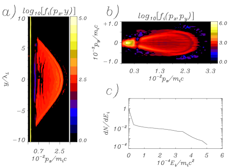
Fig.5 shows the ion phase space projections and the energy spectrum for the simulation of Fig.4, at . The dependence of the longitudinal momentum on [Fig.5 a)] and the energy spectrum [Fig.5 c)] resemble the intensity modulation of the laser pulse. The relative spread in the transverse momentum [Fig.5 b)] is very small, , showing that also in 2D the acceleration is perpendicular to the target surface. In the case we find slightly slower ion velocities and almost the same beam divergence.
In some runs, some “rippling” of the ion density front is observed. This rippling appears to be due to electron oscillations at the surface (around their quasi–equilibrium position) excited due to the finite rise time and the curvature of the laser pulse. The rippling is “imprinted” in the ion density at later times, but has no noticeable effect on the dynamics of ion acceleration. We conclude that 2D effects do not qualitatively affect ion bunch formation.
In conclusion, a regime of laser ion acceleration in cold overdense plasmas by circularly polarized pulses has been characterized by means of PIC simulations and a simple model. The dynamics is qualitatively different from the case of linear polarization where ion acceleration is driven by fast electrons. With the present scheme one may obtain moderate ion energies but very high ion densities and low beam divergence.
We acknowledge useful discussions with S. Atzeni and F. Pegoraro. Part of the numerical simulations were performed on the Linux cluster at the CINECA facility (Bologna, Italy), with the support of the INFM supercomputing initiative.
References
- (1) B. A. Remington, R. P. Drake and H. Takabe, Phys. Plasmas 7, 1641 (2000).
- (2) V. S. Khoroshkov and E. I. Minakova, Eur. J. Phys. 19, 523 (1998); S. V. Bulanov et al., Phys. Lett. A 299, 240 (2002).
- (3) N. S. P. King et al., Nucl. Inst. Meth. A 424, 84 (1999).
- (4) V. Y. Bichenkov, V. T. Tikhonchuk, and S. V. Tolonnikov, JETP 88, 1137 (1999).
- (5) M. Borghesi et al., Rev. Sci. Instr. 74, 1688 (2003).
- (6) M. Roth et al., Phys. Rev. Lett. 86, 436 (2001); S. Atzeni, M. Temporal and J. J. Honrubia, Nucl. Fusion 42, L1 (2002).
- (7) E. L. Clark et al., Phys. Rev. Lett. 84, 670 (2000); A. Maksimchuk et al., ibid. 84, 4108 (2000); A. J. Mackinnon et al., ibid. 86, 1769 (2001); T. E. Cowan et al., ibid. 92, 204801 (2004); S. P. Hatchett et al., Phys. Plasmas 7, 2076 (2000); K. Nemoto et al., Appl. Phys. Lett. 78, 595 (2001); H. Habara et al., Phys. Rev. E 69, 036407 (2004).
- (8) P. Mora, Phys. Rev. Lett. 90, 185002 (2003); S. Betti, F. Ceccherini, F. Cornolti, and F. Pegoraro, physics/0405030.
- (9) J. Denavit, Phys. Rev. Lett. 69, 3052 (1992).
- (10) L.O. Silva et al., Phys. Rev. Lett. 92, 015002 (2004).
- (11) M. S. Wei et al., Phys. Rev. Lett. 93, 155003 (2004).
- (12) A. Zhidkov, M. Uesaka, A. Sasaki, H. Daido, Phys. Rev. Lett. 89, 215002 (2002).
- (13) O. Shorokhov and A. Pukhov, Las. Part. Beams 22, 175 (2004).
- (14) S. Atzeni and J. Meyer-ter-Vehn, The Physics of Inertial Fusion (Clarendon Press, Oxford, 2004), p.389–394.