Radiation measurements in the new tandem accelerator FEL
Abstract
The Israeli Tandem Electrostatic Accelerator FEL (EA-FEL), which is based on an electrostatic Van der Graaff accelerator was relocated to Ariel 3 years ago, and has now returned to operation under a new configuration. In the present FEL, the millimeter-wave radiation generated in the resonator is separated from the electron beam by means of a perforated Talbot effect reflector. A quasi-optic delivery system transmits the out-coupled power through a window in the pressurized gas accelerator tank into the measurement room (in the previous configuration, radiation was transmitted through the accelerator tubes with 40 dB attenuation). This makes it possible to transmit useful power out of the accelerator and into the user laboratories.
After re-configuring the FEL electron gun and the e-beam transport optics and installing a two stage depressed collector, the e-beam current was raised to 2 A. This recently enabled us to measure both spontaneous and stimulated emissions of radiation in the newly configured FEL for the first time. The radiation at the W-band was measured and characterized. The results match the predictions of our earlier theoretical modeling and calculations.
1 Introduction
The Israeli electrostatic accelerator FEL (EA-FEL) is based on a 6 MeV EN-Tandem Van de Graaff accelerator, which was originally used as an ion accelerator for nuclear physics experiments [1]. The scheme employs straight geometry for the electron beam transport, where the electron gun and the collector are installed outside of the accelerator region. Lasing was reported in a previous configuration, where radiation was transmitted through the accelerator tubes with 40dB attenuation [2, 3].
In the present version of the FEL, which was relocated to Ariel, the millimeter-wave radiation generated in the resonator is separated from the electron beam by means of a perforated Talbot effect reflector [4, 5]. A quasi-optic delivery system transmits the out-coupled power through a window in the pressurized gas accelerator tank. The basic parameters of the FEL are summarized in Table 1. The acceleration voltage is set to be in order to tune the frequency of the FEL radiation to the W-band near 100 GHz.
In the following sections, we present an analysis and the results of spontaneous and stimulated emissions measurements carried out recently.
| Accelerator | |
|---|---|
| Electron beam energy: | MeV |
| Beam current: | A |
| Undulator | |
| Type: |
Magneto-static
planar wiggler |
| Magnetic induction: | =2 kG |
| Period length: | =4.444 cm |
| Number of periods: | =20 |
| Resonator | |
| Waveguide: | Curved-parallel plates |
| Transverse mode: | |
| Round-trip length: | =2.62 m |
| Out-coupling coefficient: | =7% |
| Total round-trip reflectivity: | =65% |
2 Spontaneous emission in a resonator
Random electron distribution in the e-beam causes fluctuations in current density, identified as shot noise in the beam current. Electrons passing through a magnetic undulator emit a partially coherent radiation, which is called undulator synchrotron radiation. The electromagnetic fields excited by each electron add incoherently, resulting in a spontaneous emission with generated power spectral density [6]:
| (1) |
where is the expected value of the spontaneous emission power, is the slippage time and is the detuning parameter ( is the axial velocity of the accelerated electrons and is the group velocity of the generated radiation). The spontaneous emission null-to-null bandwidth is approximately . In a FEL, utilizing a magneto-static planar wiggler, the total power of the spontaneous emission is given by:
| (2) |
where is the mode impedance, and is the DC beam current. The expected value of the total spontaneous emission power generated inside the cavity is about . The calculated spectrum of the spontaneous emission power of the Israeli EA-FEL, has a null-to-null bandwidth of 18 GHz.
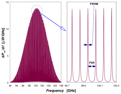
At the resonator output, the spontaneous emission spectrum generated inside the resonator is modified by a Fabry-Perot spectral transfer-function [7]:
| (3) | |||||||
where is the resonator (round-trip) length, is the total power reflectivity of the cavity, is the power transmission of the out-coupler and is the axial wavenumber of the waveguide mode. The maxima of the resonator transfer function factor occur when (where is an integer), which defines the resonant frequencies of the longitudinal modes. The free-spectral range (FSR) (the inter-mode frequency separation) is given by MHz. The transmission peak is with full-width half-maximum (FWHM) bandwidth of MHz, where is the Finesse of the resonator. The spectral line-shape of the spontaneous emission power obtained at the resonator output of the EA-FEL is shown in Fig. 1.
The noise equivalent bandwidth is defined as the bandwidth of an ideal band-pass filter producing the same noise power at its output. The noise equivalent bandwidth of a single resonant longitudinal mode is MHz. Consequently, the spontaneous emission power of mode is given by:
| (4) |
The typical bandwidth of the generated spontaneous emission power spectrum (1) is GHz. The number of longitudinal modes within the spontaneous emission bandwidth is then . Thus the total spontaneous emission power measured at the output of the resonator is given as follows:
| (5) | |||||
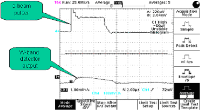
Using equation (2), we expect up to spontaneous emission power to be generated inside the resonator. From (5), the power emitted from the resonator out-coupler is reduced to . The attenuation of the wave-guiding system, delivering the power from the resonator, located inside the high-voltage terminal, to the measurement apparatus is 10dB. Consequently, the spontaneous emission power expected at the detector sight is 2.4 W. The traces shown in Fig. 2, describe the electron beam current pulse and the signal obtained at the detector video output, corresponding to the measured spontaneous emission RF power.
3 Stimulated emission
In the present operation regime of the FEL, the efficiency of energy extraction from the electron beam is given in terms of the number of wiggler’s periods by the approximate formula %. The stimulated radiation power generated inside the resonator at steady state is given as follows:
| (6) |
where kW for a beam current of A. The resulted power obtained from the out-coupler is given as follows:
| (7) |
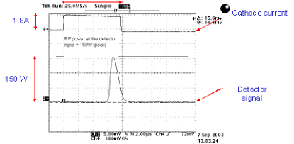
and evaluated to be kW. Considering the attenuation of
the transmission system, 700 W is expected at the detector. Fig. 3
shows recent measurement of 150 W radiation power at the end of
the optical transmission line in the measurement room. We note
that in the present preliminary experiments, only a fraction of
the cathode current was transported through the wiggler, and no
beam circulation (transport up to the collector) was achieved. The
charging of the terminal caused voltage drop of the terminal of
125 kV during the pulse duration. Evidently, the FEL had not yet
reached saturation because the radiation mode built inside the
resonator went out of synchronism with the beam before reaching
saturation.
Acknowledgments
This work was carried out at the Israeli FEL National Knowledge Center supported by The Ministry of Science, Israel, and was supported in part by the Ministry of Infrastructure.
References
- [1] A. Gover, E. Jerby, H. Kleinman, I. Ben-Zvi, B.V. Elkonin, A. Fruchtman, J.S. Sokolowski, B. Mandelbaum, A. Rosenberg, J. Shiloh, G. Hazak, O. Shahal, Nucl. Instr. and Meth. A 296 (1990) 720.
- [2] A. Abramovich, M. Canter, A. Gover, J.S. Sokolovski, Y.M. Yakover, Y. Pinhasi, I. Schnitzer, J. Shiloh, Phys. Rev. Lett. bf 82 (1999) 6774.
- [3] A. Abramovich et al., Appl. Phys. Lett. 71 (1997) 3776.
- [4] I. Yakover, Y. Pinhasi, A. Gover, Nucl. Instr. and Meth. A 445 (1996) 260.
- [5] B. Kapilevich, A. Faingersh, A. Gover, Microwave Opt. Technol. Lett. 36 (2003) 303.
- [6] Y. Pinhasi, Yu. Lurie, Phys. Rev. E 65 (2002) 026501.
- [7] Y. Pinhasi, Yu. Lurie, A. Yahalom, Nucl. Instr. and Meth. A 528 (2004) 62.