An atom interferometer for measuring loss of coherence from an atom mirror
Abstract
We describe an atom interferometer to study the coherence of atoms reflected from an evanescent wave mirror. The interferometer is sensitive to the loss of phase coherence induced by the defects in the mirror. The results are consistent with and complementary to recent measurements of specular reflection.
pacs:
03.75.BeAtom and neutron optics and 03.75.DgAtom and neutron interferometry in quantum mechanics and 39.20.+qAtom interferometry techniquesIn the past 10 years, atom interferometry has found a number of applications. Notable examples are atom gyrometers, gravimeters and accelerometers, measurements of forward scattering amplitudes for elastic collisions, and investigations of the Aharanov-Casher effect berman:1997 . Here we demonstrate a new application: interferometric characterization of an atomic mirror.
Using either dipole forces or magnetic fields, it is not difficult to make a “mirror”, i.e. a steep reflecting barrier, strong enough to reflect atoms with velocities of order 1 m/s, the velocity acquired in 5 cm of free fall. Both dipole and magnetic force mirrors can be coupled with a high quality substrate to guarantee a well defined overall flatness or curvature, thus giving rise to the evanescent wave mirror dowling:1996 ; balykin:1998 , or to the magnetic mirror hinds:1999 . It is now well known however, that a fundamental difficulty of atomic mirrors is loss of coherence due to various sources of roughness in the reflecting potential landragin:1996a ; saba:1999 ; cognet:1999 ; lau:1999 . The extremely small de Broglie wavelength associated with the typical velocities ( nm in the case of Rb at 1 m/s), imposes severe constraints on the small scale roughness of the substrate – it must be much better than henkel:1997 before the reflection can be considered specular, and therefore coherent. This experiment is the first in which an atomic mirror is used within an interferometer and as such is the first true demonstration of its coherence.
In a previous paper savalli:2002 , we reported measurements of the velocity distribution of atoms from an atom mirror and measured the fraction of specularly reflected atoms, as well as the transverse velocity profile of the diffusely reflected ones. The resolution of this measurement however, was insufficient to study the lineshape of the specularly reflected distribution – a crucial aspect characterizing the effect of the mirror on the coherence. Here we discuss a related measurement which is able to focus in more detail on the shape of the specularly reflected fraction. We have developed an atom interferometer which gives information complementary to velocity distribution measurements. We observe fringes whose contrast as a function of path difference corresponds to the coherence function of the atomic mirror, in other words to the Fourier transform of the transverse velocity distribution induced by the mirror. This measurement is particularly sensitive to the long distance behavior of the coherence function or to the velocity distribution in the specular peak, where direct velocity distribution measurements are impractical. Narrower velocity selection implies fewer atoms and worse signal to noise. The signal to noise in the interferometric technique is practically independent of the velocity resolution. It is the analog of Fourier transform spectroscopy with de Broglie waves.
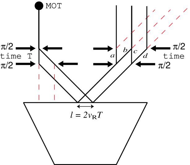
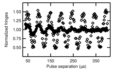
A diagram of the experiment is shown in Fig. 1. Atoms from a MOT are subjected to two pulses which transfer 2 recoil momenta to the atoms. Their time separation is . Only one of the internal atomic states is reflected by the mirror as shown by the solid line paths. After reflection the two paths are recombined by repeating the Raman pulse sequence with the same separation time. The result is an interferometer in which the two possible paths bounce off different parts of the mirror, separated by , where is the recoil velocity. By detecting atoms in only one of the two internal states, interference fringes as a function of the time are visible as shown in Fig. 2. The actual atomic trajectories are parabolic, but we have suppressed this feature in the figure because the only role played by gravity is to determine the de Broglie wavelength of the atoms at the moment they hit the mirror.
The interferometer most resembles one first discussed in Ref. borde:1992 and demonstrated in Ref. morinaga:1995 . The differences here are that we use 2 photon Raman transitions rather than 1 photon transitions kasevich:1991b and, more importantly, that we have placed an atomic mirror within the interferometer and use the fringes to study the influence of the mirror on the spatial coherence of the reflected atoms. We isolate the effect of the mirror by comparing these fringes to those obtained by applying all four pulses before the atoms hit the mirror. These fringes are also shown in Fig. 2.
It is evident that the mirror strongly reduces the fringe contrast, and we will discuss the information this reduction gives us below. But first we will give some experimental details of our setup. The apparatus is the same as that used in Ref. savalli:2002 , and the laser pulse sequence is very similar. We refer the reader to Fig. 1 of that paper for the energy level scheme. A 85Rb MOT is loaded with approximately atoms in 2 s. The atoms are prepared in the level by turning off the repumping laser before the trapping beams. They fall under gravity towards a glass prism 20 mm below. Starting 8 ms after the atoms begin to fall, two counter–propagating Raman beams are pulsed on twice for 25 s, with a period between the start of the two pulses. The two–photon detuning of the first pulse pair is where and are the frequencies of the two Raman lasers, is the hyperfine splitting in 85Rb, corrected for the atomic recoils involved in the transition. The laser parameters are such that the condition is fulfilled for .
A homogeneous magnetic bias field (750 mG), in the propagation direction of the Raman beams, ensures that only atoms in the hyperfine sublevel undergo a transition (into ). The evanescent wave laser is switched on for 20 ms, timed to coincide with the arrival of the atoms at the prism, and a second pair of Raman pulses, separated by the same period , with two–photon detuning , is applied. After the 4 pulse sequence, atoms that are not transferred to are expelled by a 2 ms pulse of light resonant for . Finally a probe beam with repumper is switched on, and the resulting fluorescence signal is measured with a photomultiplier tube. The evanescent wave mirror is described in more detail in Ref. cognet:1998 . The evanescent wave is red–detuned from resonance for , but blue–detuned for . Thus, atoms are reflected. As in Ref. savalli:2002 , the evanescent wave detuning is chosen between 500 and 2000 MHz. For more details on the Raman laser setup see savalli:2000 ; esteve:2004 .
Some atoms that do not undergo a transition stimulated by the first Raman pulse pair can still undergo a transition by spontaneous emission. These atoms make a background in our data that we measure with a second sequence this time with detuned away from resonance. This measured background is subtracted from the original signal. To make observations without the mirror, we proceed in an analogous manner except that the atoms are initially prepared in the state and a pushing laser which eliminates the atoms remaining in is applied between the 2nd and 3rd pulses. Also, all four Raman pulses, as well as the detection take place before the atoms hit the mirror.
To interpret the results, we will analyze the interferometer in terms of atom interferometry. An equivalent, velocity space interpretation is possible if one observes that the 1st two Raman pulses produce two interlaced combs in velocity space corresponding to the two different atomic internal states kasevich:1991a . The velocity space analysis proceeds by examining the effect of the mirror on the velocity distribution. In the interferometric analysis below, we work in position space and treat the atoms quantum mechanically only along the (horizontal) direction. The -component of the momentum is denoted . To treat the effect of the mirror, we use the thin phase grating approximation henkel:1994 ; henkel:1997 , which supposes that the atomic trajectories are unperturbed by mirror roughness while within the reflecting potential, and that the mirror roughness simply adds a phase (this quantity is referred to as in Ref.henkel:1997 ) to the matter wavefront. The quantity corresponds to the local vertical deviation of the mirror from a perfectly flat surface.
The atomic source has an rms velocity spread , or equivalently a coherence length . We will take the finite coherence length into account by analyzing what happens to an initial pure state in the interferometer and then performing an appropriate, incoherent, average over the possible states . For example, the initial state could correspond to a plane wave, in which case the average is over the velocity distribution of the source, or it could be considered as a wave packet. The paths in Fig. 1 can be interpreted as the trajectories of the center of mass of such a wavepacket. Taking into account the nonzero detuning of the Raman laser results in a relative phase ( or ) for each of the vertical sections of the trajectories between the 1st and 4th Raman pulses. At the output of the interferometer, after the fourth pulse, the part of the state vector corresponding to atoms in the state is given by:
| (1) |
where the letters label the 4 possible paths as in Fig. 1. If the path separation in the interferometer is greater than the source coherence length (), the paths and do not contribute to the interference pattern, only to a flat background.
The amplitudes corresponding to the paths and which do interfere can be written:
| (2) | |||||
| (3) |
Here is the initial state of the atom and is the unitary operator which describes the free evolution of a state during the time of flight from the first pulse to the mirror, or from the mirror to the last pulse.
In the above analysis, we have made the approximation that the duration of the pulses can be neglected, compared to all other time scales in the problem. In our experiment this duration is not negligible and results in an rms transverse velocity selection of the atoms by each pulse corresponding to , where is the duration of the Blackman pulse and the factor 4.04 converts the total duration of the Blackman pulse into an rms width (i.e. a half width). For a 25 s pulse, this selection corresponds to a 1 cm/s rms velocity width, or an “effective” coherence length of nm. In this case the coherence requirement which permits one to neglect any interference of the paths and is that the path separation be greater than this effective coherence length. Taking into account the finite duration of the pulses also modifies the contrast if the value of the pulse separation is close to . This effect is very small but is taken into account in the fits described below. A more detailed calculation can be found in Ref.esteve:2004 .
The interference pattern is given by the total probability of finding the atoms in the state:
| (5) | |||||
The interference term in the second line is proportional to the mirror coherence function defined in Ref.henkel:1997 :
| (6) |
where refers to a statistical average over the mirror. The interference pattern is then given by
| (7) |
Fringes are observed either by varying or and the coherence function gives their contrast. A perfect mirror has a coherence function equal to unity and a fringe contrast of 1/2.
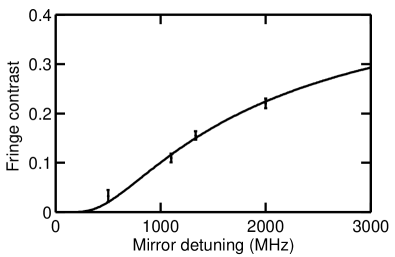
The experiment of Ref. savalli:2002 , showed that the reflected velocity distribution from the mirror is bimodal, having both a broad (diffuse) and a narrow (specular) component. This reference identified both mirror roughness and spontaneous emission as the primary causes of diffuse reflection. We therefore also expect a bimodal coherence function, consisting of a narrow part (corresponding to diffuse reflection), and a wide part corresponding to specular reflection. In terms of the coherence lengths, Ref. savalli:2002 found a length of about 100 nm for the diffuse part of the coherence function, while only a lower limit of about 1000 nm (0.1 ) could be given for the specular part. In the experiment reported here, the minimal time separation, s, corresponds to a path separation of 480 nm in the interferometer. Thus the shape of the diffusely reflected distribution is inaccessible in the present experiment. The only effect of diffuse reflection is a loss of contrast, even for s, approximately equal to the fraction of specularly reflected atoms. According to Ref. savalli:2002 , this fraction is well described by: , where the value of comes from a fit and is compared to a calculation.
In Fig. 3, we plot the fringe visibility of several runs similar to those shown in Fig. 2 as a function of the evanescent wave mirror detuning . The data were obtained for fixed (40 s) and a varying . The fit shown in the figure corresponds to times a constant. The data confirm our model of the loss of contrast and the fit yields 1.5 GHz, in reasonable agreement with the value found in Ref. savalli:2002 . One of the advantages of the interferometry technique compared to the simple velocity spectroscopy approach is evident from the error bars and dispersion of the data in Fig. 3. They are much smaller than in Fig. 4 of Ref. savalli:2002 , and indeed the value of deduced here is probably more reliable.
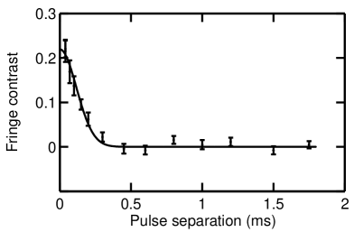
We turn now to the long range behavior of the coherence function. Fig. 4 shows the behavior of the fringe visibility as a function of the delay for a evanescent wave detuning that was fixed at GHz. The results show that the contrast decreases rapidly to zero for delays above 100 s. A Gaussian fit to the data in Fig. 4 gives a half width of 110 s. In terms of the correlation length, this result corresponds to a length of 1.3 m, just barely longer that the upper limit established in Ref. savalli:2002 . This result was unexpected.
The loss of contrast can be most easily explained by a small tilt in the mirror relative to the vertical (Raman velocity measurements determined it to be 11 mrad). Because of the tilt, the vertical velocity distribution of the atoms when they hit the mirror contributes to the horizontal velocity width after the bounce. The dominant contribution to the vertical velocity distribution comes from the vertical size of the MOT. An rms MOT size of 1.7 mm results in a 0.58 mm/s horizontal velocity spread, and this would account for our observation. The size of the MOT was not measured during the experiment, but 1.7 mm is plausible. We have considered other mechanisms for the loss of contrast such as curvature of the mirror surface, the shape of the waist of the bouncing laser beam, or diffraction of atoms from the edges. None of these is large enough to account for the observed loss of contrast. Note that even if the amount of spontaneous emission estimated in Ref. savalli:2002 is incorrect, it cannot account for the loss of contrast in Fig. 4 because its intrinsic length scale nm, (i.e. of order 1 recoil momentum is imparted to the atoms). The length scale we observe in Fig. 4 for the loss of contrast is much larger.
The main conclusion of our work is that, as in traditional optics, interferometry constitutes an extremely sensitive test of mirror surface quality. The interferometer is very well compensated for many parasitic effects effects, such as the incoherence of the source, frequency fluctuations of the lasers etc., as shown by the essentially perfect contrast observed without the mirror. Defects in the mirror are readily apparent, and can be easily quantified as shown by the small error bars in Figs. 3 and 4. The interferometer is sensitive to coherence lengths much larger than are accessible to straightforward velocity distribution measurements.
We thank M. Weitz for suggesting this experiment. This work was supported by the DGA under grant 03.34.003 and by the European Union under grant IST-2001-38863.
References
- (1) Several general discussions can be found in Atom Interferometry, edited by Paul Berman (Academic Press, San Diego, 1997), the contributions of C. Bordé, of U. Sterr et al. and of B. Young et al. are particularly relevant to our work.
- (2) J. Dowling, J. Gea-Banacloche, in Advances in Atomic, Molecular, and Optical Physics, Vol. 37, edited by B. Bederson, H. Walther (Academic Press HBJ, Boston, 1996) p.1-94, and references therein.
- (3) V. Balykin, in Advances in Atomic, Molecular and Optical Physics, Vol 41, edited by B. Bederson, H. Walther (Academic Press, Boston, 1998) p.182-260, and references therein.
- (4) E. Hinds, I. Hughes, J. Phys. D. Appl. Phys. 32, R119 (1999), and references therein.
- (5) A. Landragin, G. Labeyrie, C. Henkel, R. Kaiser, N. Vansteenkiste, C. I. Westbrook, A. Aspect, Opt. Lett. 21, 1591 (1996)
- (6) C. V. Saba, P. A. Barton, M. G. Boshier, I. G. Hughes, P. Rosenbusch, B. E. Sauer, E. A. Hinds, Phys. Rev. Lett. 82, 468 (1999)
- (7) L. Cognet, V. Savalli, P. D. Featonby, K. Helmerson, N. Westbrook, C. I. Westbrook, W. D. Phillips, A. Aspect, G. Zabow, M. Drndic, C. S. Lee, R. M. Westervelt, M. Prentiss, Europhys. Lett. 47, 538 (1999)
- (8) D. Lau, A. Sidorov, G. Opat, R. McLean, W. Rowlands, P. Hannaford, Eur. Phys. J. D 5, 193 (1999)
- (9) C. Henkel, K. Moelmer, R. Kaiser, N. Vansteenkiste, C. Westbrook, A. Aspect, Phys. Rev. A 55, 1160 (1997)
- (10) V. Savalli, D. Stevens, J. Estève, P. D. Featonby, V. Josse, N. Westbrook, C. I. Westbrook, A. Aspect, Phys. Rev. Lett. 88, 250404 (2002)
- (11) C. Bordé, in Laser Spectroscopy, edited by M. Ducloy, E. Giacobino, G. Camy (World Scientific, Singapore, 1992), p. 239
- (12) A. Morinaga, Y. Ohuchi, Phys. Rev. A 51, 1746 (1995)
- (13) M. Kasevich, S. Chu, Phys. Rev. Lett. 67, 181 (1991)
- (14) L. Cognet, V. Savalli, G. Horvath, D. Holleville, R. Marani, N. Westbrook, C. Westbrook, A. Aspect, Phys. Rev. Lett. 81, 5044 (1998)
- (15) V. Savalli, Ph.D. Thesis, Université de Paris-XI, 2002
- (16) J. Estève, Ph.D. Thesis, Université de Paris-VI, in preparation
- (17) M. Kasevich, D. Weiss, E. Riis, K. Moler, S. Kasapi, S. Chu, Phys. Rev. Lett. 66, 2297 (1991)
- (18) C. Henkel, J. Y. Courtois, A. Aspect, J. Phys. II France 4, 1955 (1994)