A High Flux Source of Cold Rubidium
Abstract
We report the production of a continuous, slow, and cold beam of atoms with an unprecedented flux of atoms/s and a temperature of a few milliKelvin. Hot atoms are emitted from a Rb candlestick atomic beam source and transversely cooled and collimated by a 20 cm long atomic collimator section, augmenting overall beam flux by a factor of 50. The atomic beam is then decelerated and longitudinally cooled by Zeeman slowing.
pacs:
39.10.+j,32.80.PjCold and slow, high-flux atomic beams are essential for high signal to noise measurements in atom interferometry experiments Berman (1997), for rapid loading of magneto-optical traps (MOTs) for production of Bose-Einstein condensates, and for the potential creation of a CW atom laser. A variety of methods have been employed over the years to create cold, intense atomic beams. Low velocity intense sources (LVIS) Lu et al. (1996), Axicons Lee et al. (1998), and 2D MOTs Riis et al. (1990); Dieckmann et al. (1998); Wohlleben et al. (2001) employ background vapor loading into a MOT. They are typically limited in total flux by the loading rate of the MOT to a few times atoms/s, though they may be pushed as high as to atoms/s, as in Schoser et al. (2002) (but with higher longitudinal temperature).
An alternative approach involves the use of a hot effusive source of atoms, with a much higher vapor pressure and followed by a deceleration and cooling stage. White light slowing has been used to produce a beam with up to Cs atoms/s Park et al. (2002). The Zeeman slower Prodan et al. (1982) requires less laser power. Using this technique, the authors in Lahay et al. have been able to produce a beam of Rb with an integrated flux of atoms/s. However, both are limited by the transverse velocity distribution of the original atomic source and can thus be made significantly more efficient by adding some form of transverse beam collimation and cooling.
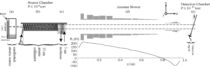
In this Letter, we report the production of a slow and cold (both transversely and longitudinally) atomic beam with a total flux of () atoms/s at 116 (45) m/s and a peak intensity of () atoms/s/. A schematic representation of the apparatus used for production of the atomic beam is shown in Fig. 1. The set-up consists of a two-stage vacuum chamber, with the source chamber separated from the detection chamber by a one-meter Zeeman slower tube.
Our source of thermal atoms originates from a Rb candlestick atomic beam source (Fig. 1(a)) Hau et al. (1994); Walkiewicz et al. (2000), which provides an intense, well collimated beam. This source has a low temperature shield around a localized hot emission point kept at C, corresponding to a 7 mtorr vapor pressure. The 2 mm emission hole lies 2 cm behind a 2 mm collimation hole, resulting in an emitted beam with a total divergence of sr. At this temperature, the resulting atomic beam has a mean velocity of 400 m/s, and a total emitted flux of atoms/s; of these emitted atoms are of which are within the designed capture velocity of the Zeeman slower (320 m/s), for a total available flux of atoms/s. Rubidium at the emission hole is replenished by capillary action via a gold-coated stainless steel mesh wick which draws from a reservoir of liquid rubidium (kept at C just above the Rb melting point of C). The pressure of the source vacuum chamber can be kept below torr, with the aid of a C cold finger. Moreover, by lining the inside of the reservoir with the same wicking mesh, uncollimated Rb is recycled, minimizing the need for reloading and source maintenance.
To optimize coupling of atoms from the source into the Zeeman slower region, we employ an atomic collimator, with a large transverse capture velocity which acts to uniformly decelerate the transverse velocity of the atoms over its entire length Aspect et al. (1990). As shown schematically in Fig. 1(b), the first 15 cm of the transverse collimation is accomplished by two pairs of nearly plane parallel ” mirrors (one pair for each transverse axis), with a cm laser beam for each axis coupled in at one end of the structure at a small angle, , relative to the mirror’s normal Aspect et al. (1990); Hoogerland et al. (1996). By an optimal choice of laser beam and mirror geometry, we greatly increase the capture velocity of the collimator relative to a comparable length of 2D molasses. Here, the mirrors in each pair are at a small angle relative to each other. Thus, upon the th reflection, the laser beam angle will be
| (1) |
By design, as the atomic beam propagates down the collimator, it becomes more and more collimated due to the radiation pressure from the laser beams which become more and more normal to the mirrors according to (1). In this way, it is possible for the laser beams to remain orthogonal to the trajectory of the atoms, which are then uniformly accelerated radially with the maximum spontaneous force, , and follow an approximately circular arc.
One can readily show that with flat mirrors it is impossible to make the wavefronts follow a perfectly circular arc (as shown by the dashed line in Fig. 1(b)). We solve for as a function of distance to arrive at
| (2) |
where is the mirror spacing. If we want the final angle to approach zero, as it should for a perfectly collimated atomic beam, should decrease linearly rather than as as given by (2). Although the laser rays will not follow the ideal trajectory as a function of , the increasingly steep angle will cause the density of the rays to increase at the end, compensating for the intensity loss from repeated reflections.
As a final consideration, note that we still require the laser beam to exit the collimator; if the final angle were normal to the mirror, the beam would simply couple back down the collimator and undo the collimation. To avoid this, we couple the laser beam non-orthogonally to the atomic velocity and correct for the resulting longitudinal Doppler shift by blue detuning the laser by (, where is the natural linewidth).
Since the collimation laser is tuned to near resonance, we sacrifice final transverse temperature for maximum collimation. Next, the 5 cm region of 2D molasses (Fig. 1(c)) rectifies this by transversely cooling the atomic beam, as well as serving as a tool for the overall alignment of the collimation structure with respect to the Zeeman slower tube (which defines an aperture of sr).
With the atomic beam collimated, transversely cooled, and efficiently coupled out of the source chamber, the longitudinal beam slowing and cooling are accomplished with a one meter long Zeeman slower (Fig. 1(d)). The slower design is of the zero-field-crossing type with a final compensating coil intended to leave very little fringe field in the experimental chamber. By design, the last six coils (which set the “negative” part of the magnetic field profile) can be driven independently of the first thirteen coils to allow for adjustment of the final velocity.
We first directly demonstrate the effectiveness of the atomic beam collimation stage by an absorption measurement at the end of the Zeeman slower, but without the magnetic field or Zeeman slowing beam present. By measuring the transmission coefficient of a probe laser through the atomic beam, we may extract the optical density (OD) of the atomic beam. Further, by sweeping the detuning, , of the probe laser, we extract the atomic beam’s velocity distribution projected onto the probe’s axis (see Fig. 1(e)).
Data resulting from the above method are shown in Fig. 2(a). In this case, the probe is normal () to the axis of the Zeeman slower, so that we may discern the transverse velocity spread. By fitting the frequency profile of the optical density to a Voigt distribution,
| (3) |
we may extract the velocity spread of the density , knowing the Lorentzian form of the cross-section (where is the transverse velocity, and the wavenumber). We find that the uncollimated emission from our source has an RMS spread of 4 m/s, which is simply a consequence of geometry (an atomic beam with a mean longitudinal velocity of around 400 m/s apertured to a half angle of 1/100th of a radian). Addition of the 2D molasses decreases this spread to 1.7 m/s, while the application of the full transverse collimation and cooling leads to a spread of 1 m/s.
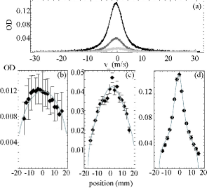
As an extension of this method, in Fig. 2(b-d) we translate the probe laser along and measure the peak OD at each point to extract the transverse mode structure of the atomic beam. To account for the structure, we assume that the normalized transverse density profile, , of the atomic beam takes the form:
| (4) |
where the Gaussian is a consequence of the collimation, and the unit step function comes from the aperturing effect of the Zeeman tube which has radius , and are normalization constants. Measurement of the OD is equivalent to projecting (4) along , meaning we will be sensitive to the mode function,
| (5) | |||||
| (6) |
Figs 2(b-d) show the data and corresponding fits using (4,6) for the atomic beam without collimation (which has ), with 2D molasses, and with full transverse collimation and cooling, respectively. Note that in all three situations, the radius, , of the disk is left as a fit parameter, and yields a value near the actual 1.9 cm radius of the Zeeman slower tube.
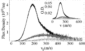
To measure the longitudinal velocity spread, we switch to a geometry where the probe is at an angle relative to the normal of the atomic beam (Fig. 3 inset). The bottom curve shows the un-collimated effusive distribution from the source. The middle and top curves represent the addition of the 2D molasses and full transverse cooling and collimation, respectively. As anticipated, both of these transverse cooling configurations work best at lower longitudinal velocities, but still give significant enhancement up to 300 m/s.
From this measurement, we may extract the flux by deconvolving the Voigt distribution (3) which may be written in terms of the flux density, , at arbitrary probe angle as
| (7) |
Here, is the longitudinal velocity, is the detuning of the probe from resonance, the natural linewidth, and the resonant cross section of the transition which is weighted by the average oscillator strength . (The probe is chosen to be linearly polarized, and averaging over the available to transitions leads to .)
Without the Zeeman slower, in the limit where the width of the longitudinal velocity distribution, contained in , is much larger than , we may pull the flux out of the integral and rearrange to obtain
| (8) |
Thus, by measuring the OD at fixed , having already mapped out the beam’s transverse mode to extract , we may readily extract the atomic beam’s flux density (Fig. 3) from the OD measurement (inset). The overall efficiency of the transverse collimation and cooling process can be summarized as follows: of the /s which are “capturable” by the Zeeman slower, only /s arrive in the main chamber due to the solid angle of the Zeeman tube. Transverse collimation and cooling increases this capturable flux to /s. This is a factor of 25 enhancement and means that we can couple a full of the atoms which are usable from our source through the Zeeman slower structure.
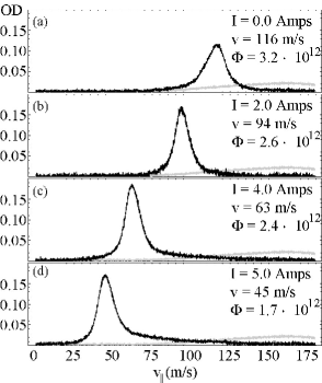
The measured effect of the Zeeman slower on the atomic beam with various magnetic field configurations is shown in Fig. 4. In this series, we choose our probe beam to be at to the axis of the atomic beam, to allow for maximum velocity sensitivity. In Fig. 4(a) we show the effect of turning on the positive field of the Zeeman slower (as defined by the first thirteen coils in Fig. 1(d)). As we increase the field in the negative region as shown in Figs 4(b-d), we can continuously tune the final velocity of our atomic beam, while always maintaining a high overall flux (for the cases shown, tuning the velocity from 116 to 45 m/s).
With the slower activated, the width of the longitudinal velocity distribution is narrow, and we may substitute for in (7), where is the average velocity of the atomic beam. We integrate and rearrange to get the total flux
| (9) |
So, by measuring the spatial mode, of the atomic beam in each of the cases in Fig. 4 (as we did in Figs 2(b-d)), we may readily compute the total flux of the atomic beam.
Note that in these figures, the stated flux results from integrating the measured OD over the peak. As we proceed to lower final velocities, the flux in this peak gradually drops and the distribution begins to form a tail in the high velocity region. In fact, integrating over the total distribution (up to 150 m/s) yields a total flux of atoms/s in all cases, and the presence of the high tail has been traced to minor ripples in the magnetic field at the end of the Zeeman slower.
Importantly, the signal enhancement for the Zeeman slowed distribution due to the transverse collimation and cooling exceeds the factor of 25 observed for the unslowed beam. We measure () atoms/s at 116 (45) m/s, to be compared to () atoms/s without any transverse collimation and cooling, for factor of 50 in overall increase.
Acknowledgements.
This work was supported by the Air Force Office of Scientific Research, ARO-MURI, and NASA. CS was supported by a National Defense Science and Engineering Grant sponsored by the U.S. Department of Defense. The authors would like to acknowledge D. Rogers, J. MacArthur and A. Sliski for invaluable technical expertise and thank W. Hänsel for useful discussions and valuable support.References
- Berman (1997) P. R. Berman, Atom Interferometry (Academic Press, London, 1997), 1st ed.
- Lu et al. (1996) Z. T. Lu et al., Phys. Rev. Lett. 77, 3331 (1996).
- Lee et al. (1998) K. I. Lee et al., J. Korean. Phys. Soc. 33, 365 (1998).
- Riis et al. (1990) E. Riis, D. S. Weiss, K. A. Moler, and S. Chu, Phys. Rev. Lett. 64, 1658 (1990).
- Dieckmann et al. (1998) K. Dieckmann, R. J. C. Spreeuw, M. Weidemüller, and J. T. M. Walraven, Phys. Rev. A 58, 3891 (1998).
- Wohlleben et al. (2001) W. Wohlleben, F. Chevy, K. Madison, and J. Dalibard, Eur. Phys. J. D. 15, 237 (2001).
- Schoser et al. (2002) J. Schoser et al., Phys. Rev. A 66, 023410 (2002).
- Park et al. (2002) S. E. Park et al., J. Opt. Soc. Am. B 19, 2595 (2002).
- Prodan et al. (1982) J. V. Prodan, W. D. Phillips, and H. Metcalf, Phys. Rev. Lett. 49, 1149 (1982).
- (10) T. Lahay et al., cond-mat/0405013.
- Hau et al. (1994) L. V. Hau, J. A. Golovchenko, and M. M. Burns, Rev. Sci. Instr. 65, 3746 (1994).
- Walkiewicz et al. (2000) M. R. Walkiewicz, P. J. Fox, and R. E. Scholten, Rev. Sci. Instr. 71, 3342 (2000).
- Aspect et al. (1990) A. Aspect et al., Chemical Physics 145, 307 (1990).
- Hoogerland et al. (1996) M. D. Hoogerland et al., Appl. Phys. B 62, 232 (1996).