The ATLAS liquid argon hadronic end-cap calorimeter: construction and selected beam test results
Abstract
ATLAS has chosen for its Hadronic End-Cap Calorimeter (HEC) the copper-liquid argon sampling technique with flat plate geometry and GaAs pre-amplifiers in the argon. The contruction of the calorimeter is now approaching completion. Results of production quality checks are reported and their anticipated impact on calorimeter performance discussed. Selected results, such as linearity, electron and pion energy resolution, uniformity of energy response, obtained in beam tests both of the Hadronic End-Cap Calorimeter by itself, and in the ATLAS configuration where the HEC is in combination with the Electromagnetic End-Cap Calorimeter (EMEC) are described.
1 INTRODUCTION
ATLAS is a general purpose detector in construction at the collider at CERN. It is designed to exploit the full discovery potential as given by center of mass energy of TeV and the highest luminosity of more than . The optimization of the detector is driven by the requirements to detect new particles and physics processes as e.g. the Higgs boson in the decay , heavy and like particles or supersymmetric particles. In the ATLAS detector the hadronic liquid argon (LAr) end-cap calorimeter (HEC) [1, 2] covers the pseudorapidity range .
To fully exploit the physics potential of ATLAS, an energy resolution for jets of typically is required for the HEC. The desired linearity of the energy response measured has to stay within [2].
The total energy containment up to the highest energies as well as an acceptable low background in the muon chambers require a calorimeter thickness of at least interaction lengths () including the electromagnetic end-cap calorimeter (EMEC) in front of the HEC. Fast electronics is needed in order to keep the pile-up low.
Liquid argon technology was chosen as the active medium for its robustness against the high radiation levels present in this forward region.
In the following the status of the construction of the HEC is discussed and the most recent results from the beam test measurements are presented.
2 THE ATLAS HADRONIC END-CAP CALORIMETER
The LAr HEC [1, 2] is a sampling calorimeter with flat copper absorber plates. It shares the two end-cap cryostats together with the EMEC and forward calorimeter (FCAL).
The HEC is structured in two wheels, the front HEC and the rear HEC wheel, placed in the cryostat behind the EMEC wheel. Each wheel has an outer diameter of about . The length of HEC (HEC) is (). The thickness of the copper absorber plates is for HEC and for HEC, with the first plate being half of this normal thickness in either case. Each wheel is made out of identical modules. The weight of HEC is and that of HEC is . In total gaps for HEC and gaps for HEC are instrumented with a read-out structure. Longitudinally they are read out as segments of and gaps for HEC and and gaps for HEC. The read-out structure is based on the principle of an electrostatic transformer (EST) [3]. The size of the liquid argon gaps between the electrode structure is .
The transverse granularity, driven by the aim to reconstruct the decay at high , is for the region and beyond .
The HEC employs the concept of “active pads”: the signals from individual pads are fed into separate preamplifiers (based on highly integrated GaAs electronics) and summed actively. The electronics boards with these IC’s are positioned directly at the module periphery, the chips are operated in the liquid argon. Thus the input capacitances are minimized and a short signal rise time ensured. The use of cryogenic GaAs preamplifiers and summing amplifiers provides the optimum signal-to-noise ratio for the HEC. The “active pad” electronics has been employed in more than cold tests with and without beam. It has proven to be very reliable.
3 CONSTRUCTION STATUS
The construction of the HEC is almost finished: all the modules are assembled and have passed the cold tests, all four wheels are assembled and one full end-cap with HEC and HEC wheels is fully integrated into the end-cap cryostat together with the EMEC and the FCAL. The level of high voltage (HV) problems after integration is , not causing any acceptance losses, but rather a few specific corrections for some channels. Only one out of read-out channels is not operational, corresponding to a failure rate of .
4 GENERAL 2002 BEAM TEST SETUP
The beam test has been carried out in the H6 beam-line at the CERN SPS providing hadrons, electrons or muons in the energy range . The load in the liquid argon cryostat consisted of one EMEC module ( of the full EMEC wheel), three HEC modules ( of the full HEC wheel) and two HEC modules. Constrained by the cryostat dimension the depth of the HEC modules were half of the ATLAS modules. The impact angle of beam particles was with respect to the front plane, yielding a non-pointing geometry of the setup in (vertically) unlike the ATLAS situation.
In front of the first EMEC layer a presampler end-qcap module was placed inside the cryostat. It allowed studies of preshower corrections with optional additional material in front of the cryostat.
Finally, scintillators for triggering and timing and MWPCs with horizontal and vertical wire planes for beam position reconstruction were present further upstream in the beam line.
5 SIGNAL RECONSTRUCTION AND CALIBRATION
In the analysis of the beam test data, the signal reconstruction follows closely the methods used in previous stand-alone beam tests of the EMEC [4] and the HEC [5]. The output signals of the cold HEC summing amplifiers and the raw signals from the EMEC were carried to the front-end boards (FEB) outside the cryostat. Here the amplification of the EMEC signals and signal shaping of all signals was performed. The signals were sampled at a rate of and stored in a switched capacity array of the FEB. For each event () samples per EMEC (HEC) channel were recorded together with the MWPC response, trigger information and the TDC measured delay between the trigger and the sampling clock. The raw ADC samples were processed with an optimal filtering (OF) method [6] using event samples.
For the HEC the detailed knowledge of each component in the electronics chain and the form of the input calibration pulse was used to determine the response function, which was then used to predict the shape for the physics signals.
The resulting predicted physics shapes together with the autocorrelation matrices from noise runs was used for the computation of the OF weights. Unlike the final situation in ATLAS with its fixed delay between trigger and sampling clock the beam test trigger was asynchronous with respect to the sampling clock. The OF weights were therefore calculated in steps of in order to fill the trigger window and parametrized by a order polynomial. The accuracy for the amplitude reconstruction following this method achieved the level of . The required conversion factor from ADC counts to nA was obtained by a proper study of calibration pulse hight.
6 ENERGY RECONSTRUCTION
The total signal deposited in the calorimeter was estimated on event by event basis using a cell-based two-dimensional topological clustering algorithm.
The electronic noise (in nA) for each cell was obtained by studying either muon data or time samples located outside the physics pulse time region.
Each cluster consisted of at least one cell with a signal-to-noise ratio above 4 (). A threshold on the absolute value of the signal-to-noise ratio, , was applied to all other cells. They were included in the cluster if they shared at least one edge with a cluster member cell satisfying . The symmetric cuts on the cell and neighbor level avoided biases due to electronics noise. Two super-clusters for the EMEC and the HEC were defined by summing all cluster signals in the EMEC and the HEC respectively. For the HEC the signals in the layer were multiplied by in order to account for the smaller sampling fraction.
7 RESPONSE TO ELECTRONS
From Monte Carlo simulations of the beam test configuration the leakage outside the EMEC was found to be very small for electrons and has been neglected. Therefore the ratio of the known beam energy () and the sum of all signals in the EMEC in nA defined the electromagnetic scale factor, , where the error is here statistical only. The variation with energy tests the linearity in the energy range considered and was found to be better than .
The energy resolution for electrons has been studied using the super-cluster mentioned above.
In data the energy resolution was found to be after noise subtraction. The noise varies with energy due to the non-fixed cluster size. GEANT3 [7, 8] and GEANT4 [9]) based Monte Carlo simulations are in good agreement with the data and yield for GEANT3 an energy resolution while GEANT4 yield a . Further tuning is required for ATLAS to improve the fair agreement with the data.
8 RESPONSE TO PIONS
The electromagnetic scale for the HEC was taken from the previous stand-alone beam test [10], , taking the modified electronics into account. A good agreement of the total visible energy in the EMEC and HEC for pions with Monte Carlo simulations based either on GEANT3 or the quark-string-gluon-plasma (QGSP) model of GEANT4 is observed, while the GEANT4 low-and-high-energy-pion-parameterization (LHEP) model deviate largely from data.
9 WEIGHTING
The non-compensating nature of the two calorimeters makes weighting of hadronic energy deposits necessary. A cell based weighting method which was successfully used in previous experiments [11, 12] needs a detailed simulation on the cell level, which is not yet available for ATLAS. Therefore a more coarse weighting scheme on the super-cluster level has been applied.
With the leakage outside the detector volume as predicted by the Monte Carlo and the known beam energy 6 weights (3 for the EMEC and 3 for the HEC) have been fitted from the two super-cluster energies and their energy density, leading to the weighted energies .
The noise subtracted energy resolution for pions, , see Fig. 1,
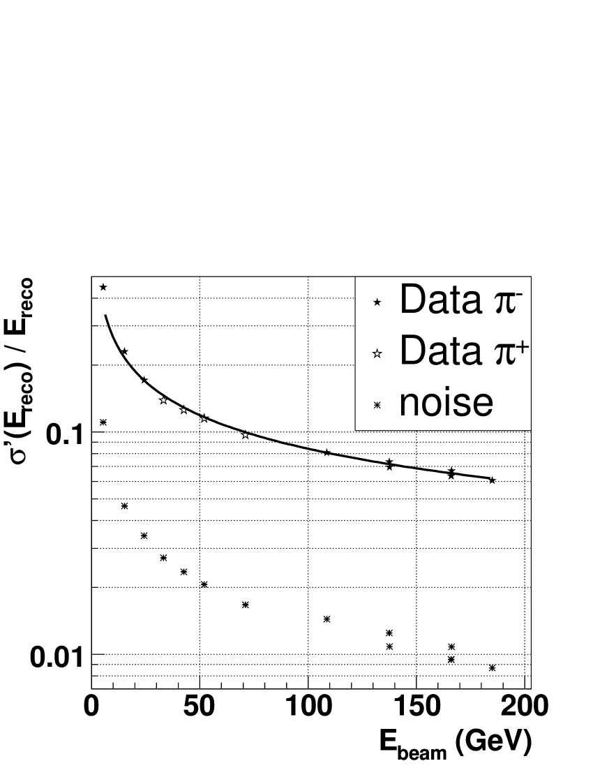
is slightly worse than expected from Monte Carlo. The GEANT3 simulation predicts a and a GEANT4 LHEP and QGSP simulations predict an energy resolution sampling term of and , respectively. In general the GEANT4 models seem closer to the data, but neither QGSP and LHEP give an optimal description. The different energy dependence of the GEANT4 predictions is also reflected in non-vanishing constant terms: for LHEP and for QGSP.
The ratio of the combined weighted energy of EMEC and HEC over the combined electromagnetic energy yield the effective -ratio for the end-cap calorimeters ranging from at to at for pions. Fig. 2
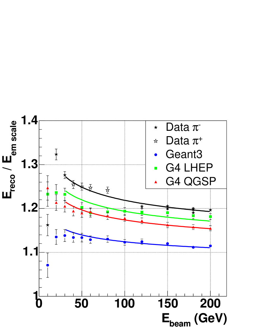
shows this ratio for the data and the different MC models. The energy dependence is in all cases rather similar. However the MC predictions are here substantially below the data, with GEANT3 being especially low.
References
- [1] The ATLAS Collaboration, ATLAS Liquid Argon Calorimeter Technical Design Report, CERN-LHCC-96-041, ATLAS TDR 2,15 December 1996.
- [2] The ATLAS Collaboration, ATLAS Calorimeter Performance Design Report, CERN-LHCC-96-040, ATLAS TDR-1, 13 January 1997.
- [3] J. Colas, M. Pripstein, W.A. Wenzel, Nucl. Inst. and Meth. A 294 (1990) 583.
- [4] B. Aubert et al. (ATLAS Electromagnetic Liquid Argon Calorimeter Collab.), Nucl. Inst. and Meth. A 500 (2003) 178
- [5] B. Dowler et al. (ATLAS Liquid Argon Hadronic End-Cap Calorimeter Collab.), Nucl. Inst. and Meth. A 482 (2002) 94
- [6] W. E. Cleland and E. G. Stern, Nucl. Inst. and Meth. A 338 (1994) 467.
- [7] R. Brun et al., GEANT3, CERN-DD/EE/84-1 (1986)
- [8] A. Kiryuning and D. Salihagić, Monte Carlo for the HEC Prototype: Software and Example of Analysis, ATLAS HEC Note-063 (1998).
- [9] S. Agostinelli et al., GEANT4 - a simulation toolkit, Nucl. Inst. and Meth. A 506 (2003) 250.
- [10] D. Dowler et al. (ATLAS Liquid Argon HEC Collab.), Nucl. Inst. and Meth. A 482 (2002) 94.
- [11] I. Abt et al. (H1 Collab.), Nucl. Inst. and Meth. A 386 (1997) 348.
- [12] B. Andrieu et al. (H1 Calorimeter Collab.), Nucl. Inst. and Meth. A 336 (1993) 499.