Present address: ]Nano-Optics Group, Laboratory for Physical Chemistry, Swiss Federal Institute of Technology (ETH), Zürich, Switzerland
Also at: ]FOM Institute for Atomic and Molecular Physics AMOLF, Center for Nanophotonics, Kruislaan 407, 1098 SJ Amsterdam, The Netherlands
Also at: ]FOM Institute for Atomic and Molecular Physics AMOLF, Center for Nanophotonics, Kruislaan 407, 1098 SJ Amsterdam, The Netherlands
Optical extinction due to intrinsic structural variations of photonic crystals
Abstract
Unavoidable variations in size and position of the building blocks of photonic crystals cause light scattering and extinction of coherent beams. We present a new model for both 2 and 3-dimensional photonic crystals that relates the extinction length to the magnitude of the variations. The predicted lengths agree well with our new experiments on high-quality opals and inverse opals, and with literature data analyzed by us. As a result, control over photons is limited to distances up to 50 lattice parameters (m) in state-of-the-art structures, thereby impeding large-scale applications such as integrated circuits. Conversely, scattering in photonic crystals may lead to novel physics such as Anderson localization and non-classical diffusion.
pacs:
42.70.Qs, 42.25.Dd, 42.25.Fx, 81.05.ZxThe promise of full control over emission and propagation of light has led to a widespread pursuit of photonic crystals in recent years soukoulis01 . Photonic crystals are dielectric structures in which the refractive index varies periodically over length scales comparable to the wavelength of light. For three-dimensional periodicities, such crystals promise a photonic band gap, i.e., a frequency range for which emission and propagation of light are completely forbidden. Ideally, photonic band gap crystals will form a backbone in which many photonic devices, such as ultrasmall waveguides, cavities and light sources, are combined to create optical integrated circuits noda03 . This requires photonic crystals with negligible optical extinction over millimeter distances noda03 .
Tremendous progress has been made in the fabrication of photonic bandgap materials of the required high refractive index-materials wijnhoven ; blanco00 ; noda00 ; vlasov01 , with low point and plane defect densities vlasov01 . Structural variations in size and position of the building blocks, however, are intrinsic to three- and two-dimensional (3D, resp. 2D) photonic crystals alike, amounting to at least 2 to 7% of the lattice spacing in all current state-of-the-art photonic crystals wijnhoven ; babacrete00 . While displacements are well-known in condensed matter ashcroft76 , size polydispersity of individual unit cell building blocks, including roughness, is intrinsic to meta-materials such as photonic crystals. All such variations can ultimately be traced back to basic thermodynamic arguments ashcroft76 , but are at present probably limited by materials science. These deviations from perfect periodicity cause scattering, and hence exponential attenuation of coherent beams propagating through photonic crystals over lengths , also known as the ‘(extinction) mean free path’. After propagating over a distance , a coherent light beam is converted to a diffuse glow that corrupts the functionality of any photonic integrated circuit. Conversely, short mean free paths open up novel physics related to diffusion of light and ultimately Anderson localization of light John87 ; sheng . Therefore, it is crucial to obtain the relation between the extinction length and the structural disorder. In this paper, we derive such a relation and test it against available experimental results Koenderink04 .
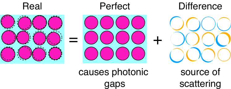
We consider extinction in photonic crystals due to scattering by size polydispersity and displacements from lattice sites of the structural units (size ) that compose the unit cell (lattice spacing ). Light scattering is caused only by the difference in refractive index profile of the displaced, slightly polydisperse building blocks as compared to the ideally ordered structure. As illustrated in Fig. 1, this difference is a collection of thin shells of high and low index material. The polydispersity and displacements of the building blocks translate linearly into the shell thickness . Since in many photonic crystals, such as cubic (3D) or hexagonal (2D) structures, light transport is isotropic, we treat the ideal crystal as an effectively homogeneous medium with index equal to the volume-averaged refractive index averagenote . Within this framework, the inverse extinction length
| (1) |
is the product of three factors hulst81 : Rayleigh’s extinction cross section of each shell, the number density of shells , and a wavelength-dependent geometrical factor which embodies corrections beyond Rayleigh scattering transportnote . Since the volume of each shell is proportional to its thickness , Rayleigh’s extinction cross section is proportional to , where is the index contrast relative to the background medium. Even though scattering by each shell is generally weak, the huge density set by the number of structural units per unit cell causes the scattering mechanism to be important. For Rayleigh scatterers, in the low-frequency limit, the dimensionless factor equals unity. For weakly scattering shells, the Rayleigh-Gans approach is suited to find hulst81 ; transportnote .
We now focus on the extinction length in 3D photonic crystals that consist of spheres (mean radius ), such as opals and inverse opals where many data are available. Size polydispersity results in scattering due to thin spherical shells with a Gaussian distribution of thicknesses. The inverse extinction length scales quadratically with the size polydispersity and with , since Rayleigh’s extinction cross section for a shell of thickness reads (cf. hulst81 ), with the wave vector in the effective medium. We find that the Rayleigh-Gans correction hulst81
| (2) |
reduces the well-known fourth power Rayleigh increase of extinction to a nearly quadratic dependence on wave vector approxnote . We have checked the validity of our result using the exact Mie-solution for spherical shells. Although for and the Rayleigh-Gans result underestimates the extinction loss compared to Mie theory, the Mie-model reproduces the quadratic scaling with frequency and shell thickness. Our model captures both the effect of polydispersity and displacements : calculations of show that both effects are similar in magnitude, and can be combined by taking an effective shell thickness . From now on, indicates effective shell thicknesses normalized by the shell radius. An essential result of our paper is that given the current fabrication accuracies of , the maximum extinction length is only 50 lattice spacings in high-index crystals at relevant frequencies.
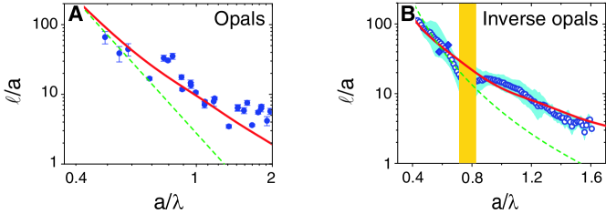
Enhanced backscattering measurements obtained earlier by us have allowed us to determine the mean free path transportnote in synthetic opals, i.e., fcc crystals of close packed polystyrene spheres with and koenderink00 . In Figure 2(A), we plot for a wide normalized frequency range, obtained with and nm, and many different . We see that decreases from for frequencies below first order diffraction, to at the highest frequencies, where we have converted the wavevector from the scattering model to the frequency scale typical of photonic crystals. The data and our model agree well on both the observed decrease of with and the magnitude of , which confirms that extinction is due to non-uniformities and displacements of the spheres, assuming . This value matches well with the cumulative effect of polydispersity and rms displacements of spheres from their lattice sites ( of the nearest neighbor distance), as independently determined by small angle X-ray scattering megens01 . In contrast, the data refute the often assumed Rayleigh dependence vlasov99b ; blanco00 . The degree of extinction is also inconsistent with the common assumption that scattering is due to point defects, e.g., missing spheres: From the cross-section of a sphere hulst81 we calculate that the observed scattering would require a density of missing spheres larger than , an order of magnitude larger than the estimated density vlasov99b ; vlasov01 .
We have carried out new experiments to probe scattering losses in photonic crystals with high photonic interaction strength, i.e. inverse opals in a TiO2 backbone. The strength of the interaction of a photonic crystal with light is gauged by the relative bandwidth of the lowest order gap in the dispersion relation, see Ref. soukoulis01 , p. 194. The generally pursued large interaction strengths require a large index contrast and are thus associated with stronger scattering, due to the factor in Rayleigh’s cross section. While the magnitude of the non-uniformities is similar to those in the direct opals wijnhoven , the inverse opals present a much larger index contrast (). We have determined the frequency dependence of from total diffuse transmission (, with the sample thickness transportnote ). We used white-light FTIR spectroscopy to cover a wide normalized frequency range for many samples with nm to nm. To obtain the absolute magnitudes of the mean free paths we calibrated our measurements by measuring the absolute values of the transmission (closed symbols) and using enhanced-backscattering data koenderink00 . Figure 2(B) shows that decreases from at to only at . This decrease of for the inverse opals is in excellent correspondence with our prediction (solid curve), taking a non-uniformity that is consistent with independent structural data wijnhoven .
| Ref. | / 11footnotemark: 1 | 22footnotemark: 2 | 33footnotemark: 3 | 44footnotemark: 4 | ||
|---|---|---|---|---|---|---|
| pradhan97 55footnotemark: 5 | 66footnotemark: 6 | |||||
| koerdt03 55footnotemark: 5 | cp77footnotemark: 7 | |||||
| tarhan96 55footnotemark: 5 | ||||||
| vlasov99b 55footnotemark: 5 | cp | |||||
| park99 55footnotemark: 5 | cp | |||||
| huang01 88footnotemark: 8 | cp | |||||
| miguez97 55footnotemark: 599footnotemark: 9 | cp | |||||
| Fig. 2(a)88footnotemark: 8 | cp | |||||
| Fig. 2(b)99footnotemark: 9 | cp |
: refractive indices of spheres, resp. background medium. 22footnotemark: 2The are for in the first stop gap. 33footnotemark: 3Decay powers obtained by fitting to the data (), resp. model Eq. (1,2) in the same frequency range (). 44footnotemark: 4Effective shell radii that best fit the data over the full available frequency range. 55footnotemark: 5Transmission. 66footnotemark: 6Bcc instead of fcc. 77footnotemark: 7cp=close-packing, . 88footnotemark: 8Enhanced backscattering. 99footnotemark: 9Diffuse total transmission.
To further test the validity of our model, we have analyzed transmission data reported in many papers encompassing fcc and bcc photonic crystals, with sphere volume fractions from to and index contrasts from to vlasov99b ; tarhan96 ; koerdt03 ; pradhan97 ; miguez97 ; park99 ; huang01 . Extinction causes the coherent-beam transmission outside stop gaps to decrease according to Lambert-Beer’s law . In all cases, except of course for the dilute crystal pradhan97 , fitting a power law dependence to each data set shows that extinction does not increase according to Rayleigh’s law. Indeed, Table 1 shows that we find exponents in reasonable correspondence to the exponents predicted by our model in the same frequency windows. Similar exponents were recently also observed in Ref. rengarajan05 . Fits to our model further show that extinction lengths for the wide range of crystals agree with , consistent with typical sphere polydispersities and displacements of –, as reported in Table 1. The quantitative agreement of with Eqs. (1,2) confirms that polydispersity and displacements of unit cell building blocks determine scattering loss in 3D photonic crystals.
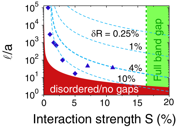
Given the success of our model, we can now use it to infer the general dependence of the extinction length on the photonic interaction strength and the non-uniformity . In Figure 3 we present both and that are calculated as a function of index contrast . It is clear that the extinction length decreases both with increasing photonic strength and with increasing structural disorder. We also present the experimental extinction data from Table 1 for fcc opals and inverse opals, showing again a good agreement with our model with . A photonic band gap requires interaction strengths beyond ; extinction lengths less than 20 lattice spacings are expected at the current level of fabrication accuracy. Ultimately, one hopes to realize photonic crystals that combine many optical functions. Recent technology roadmaps foresee crystals containing optical functions per mm2 (Ref. noda03 , p. 245), requiring negligible loss over more than mm distances. From the general scaling of extinction with non-uniformity we conclude that applications of photonic band gap crystals in circuits require a formidable tenfold increased perfection in statistical fabrication accuracy to , or subnanometer precision. Such an improvement is far beyond the current state-of-the-art soukoulis01 ; noda03 .
Although 3D photonic crystals potentially offer the best platform for photonic crystal functionality, 2D photonic crystals possess many of the desired properties with the advantage of ease of fabrication. While the fabrication methods are radically different, 2D photonic crystals suffer from similar polydispersity and displacements of their unit cell building blocks as 3D crystals babacrete00 . To obtain the scattering losses, we consider 2D crystals of infinitely long cylinders. Now, Rayleigh’s cross section per unit length of thin cylindrical shells of thickness and radius increases with the cube of the optical frequency hulst81 . In the relevant range of cylinder radii, the Rayleigh-Gans model causes the dependence of in the Rayleigh-limit to be reduced to since approxnote
| (3) |
For a hexagonal lattice of air cylinders in silicon with , typical for macroporous silicon crystals gruning95 , we find for frequencies near lowest order stop gaps, assuming a non-uniformity of 5%. A much larger is required for integrated circuit applications.
Many efforts currently focus on quantifying losses in 2D crystals made from high index slabs on lower index cladding layers, for which the nonuniformity is around 5% soukoulis01 ; babacrete00 . Although the guided wave profile normal to the slab is not incorporated in our model, we believe that Eq. (3) yields a reasonable estimate of scattering due to nonuniformity of the air holes in such structures. Similar to 3D, applications of 2D structures in photonic crystal integrated circuits require a formidable increase in fabrication accuracies beyond the current state-of-the-art soukoulis01 ; noda03 . These scattering losses add to currently widely studied out-of-plane scattering that is intrinsic even to hypothetical perfectly fabricated 2D crystal designs benisty00 . In contrast to out-of-plane loss, however, statistical variations cannot be reduced by design optimization.
Scattering in photonic crystals opens opportunities to explore new phenomena in multiple scattering of light sheng . Photonic crystals allow unique control over fundamental aspects, such as the transport velocity or anisotropies of light diffusion. A fascinating application is the possibility to localize light, which could serve to enhance non-linear interactions John87 . According to the usual Ioffe-Regel criterion, Anderson localization occurs when the mean free path is so strongly reduced that its product with the wave vector equals one: . It has been proposed that in photonic crystals this challenging criterion is relaxed to , with the modification of the photonic density of states (DOS) relative to free space Busch99 . Since the DOS is strongly reduced in photonic gaps, localization of light may even be feasible with the relatively long mean free paths predicted by our model.
We thank Allard Mosk, Peter Lodahl, Philip Russell, and Thomas Krauss for stimulating discussions. This work is part of the research program of the “Stichting voor Fundamenteel Onderzoek der Materie (FOM),” which is financially supported by the “Nederlandse Organisatie voor Wetenschappelijk Onderzoek (NWO).”
References
- (1) C. M. Soukoulis, ed., Photonic Crystals and Light Localization in the Century (Kluwer, Dordrecht, 2001).
- (2) S. Noda, T. Baba, Roadmap on Photonic Crystals (Kluwer, Boston, 2003).
- (3) J. E. G. J. Wijnhoven, W. L. Vos, Science 281, 802 (1998).
- (4) A. Blanco, et al., Nature 405, 437 (2000).
- (5) S. Noda, K. Tomoda, N. Yamamoto, A. Chutinan, Science 289, 604 (2000).
- (6) Y. A. Vlasov, X. Z. Bo, J. C. Sturm, D. J. Norris, Nature 414, 289 (2001).
- (7) N.W. Ashcroft, N.D. Mermin, Solid State Physics (Holt, Rinehart, and Winston, New York, 1976), pp. 616–620.
- (8) T. Baba, N. Fukaya, in soukoulis01 pp. 105–116 (2001); M. Notomi, et al., Phys. Rev. Lett. 87, 253902 (2001); S. Og-awa, K. Tomoda, S. Noda, J. Appl. Phys. 91, 513 (2002).
- (9) S. John, Phys. Rev. Lett. 58, 2486 (1987).
- (10) P. Sheng, ed., Scattering and localization of classical waves in random media, (World Scientific, Singapore, 1990).
- (11) A.F. Koenderink and W.L. Vos, arxiv.org/abs/physics/0406052.
- (12) Interference between scattering and photonic structure is neglected since (I) the extinction lengths appears to be unaffected when the frequency is tuned though a photonic gap, even when the gaps severely confine the propagation of light koenderink00 , (II) reflects loss averaged over all allowed Bloch modes, which strongly reduces the importance of individual Bloch mode profiles.
- (13) H. C. van de Hulst, Light Scattering by Small Particles (Dover, New York, 1981).
- (14) Anisotropic scattering can be incorporated in to obtain the transport mean free path sheng . The difference is presently not relevant as anisotropy corrections are modest for difference shells originating from displacements.
- (15) This approximation for holds to within 5% (Eq. (2)) resp. 10% (Eq. (3)) for .
- (16) A. F. Koenderink, et al., Phys. Lett. A 268, 104 (2000).
- (17) Y. A. Vlasov, M. A. Kaliteevski, V. V. Nikolaev, Phys. Rev. B 60, 1555 (1999).
- (18) Z. Cheng, W. B. Russel, P. M. Chaikin, Nature 401, 893 (1999).
- (19) M. Megens, W. L. Vos, Phys. Rev. Lett. 86, 4855 (2001).
- (20) Ì. Ì. Tarhan, G. H. Watson, Phys. Rev. Lett. 76, 315 (1996).
- (21) C. Koerdt, G. L. J. A. Rikken, E. P. Petrov, Appl. Phys. Lett. 82, 1538 (2003).
- (22) R. D. Pradhan, J. A. Bloodgood, G. H. Watson, Phys. Rev. B 55, 9503 (1997).
- (23) H. Míguez, et al., Appl. Phys. Lett. 71, 1148 (1997).
- (24) S. H. Park, B. Gates, Y. N. Xia, Adv. Mater. 11, 462 (1999).
- (25) J. Huang, et al., Phys. Rev. Lett. 86, 4815 (2001).
- (26) R. Rengarajan, D. Mittleman, C. Rich, and V. Colvin, Phys. Rev. E 71, 016615 (2005).
- (27) R. B. Wehrspohn, et al., in soukoulis01 , pp. 143–154 (2001).
- (28) H. Benisty, et al., Appl. Phys. Lett. 76, 532 (2000).
- (29) K. Busch and S. John, Phys. Rev. Lett. 83, 967 (1999).