Two-dimensional PIC-MCC simulations of capacitively coupled radio-frequency discharge in methane
A L Alexandrov 111To whom correspondence should be addressed (a_alex@itam.nsc.ru) and I V Schweigert
Institute of Theoretical and Applied Mechanics, Novosibirsk, 630090, Russia
Abstract
Two–dimensional capacitively coupled radio frequency discharge in methane is simulated by PIC-MCC method. The results were obtained in pressure range 50-300 mTorr and voltage range 40-180 V for discharge frequency 13.56 MHz. The electron energy and electron–methane reaction rates spatial distributions show existence of two regimes of discharge glow: a) with active sheaths, when electrons are hot in electrode sheaths and cold in the middle of discharge so the electron–neutral reactions strongly dominate in sheaths regions; b) with volume domination, when the electron energy is more uniform and the reactions take place in all discharge volume. The second regime is usually observed for low discharge voltages, and turns to the first one with voltage increasing. Besides, simulation of chemical reactions in methane plasma was also fulfilled to find the gas mixture composition in discharge volume. The results are in agreement with the known experimental data.
1 Introduction
The radio-frequency (rf) methane plasma, used for producing carbon films in plasma-enhanced chemical deposition (PECVD) reactors, is an object of interest for investigations. The numerical modelling of capacitively coupled radio-frequency (ccrf) plasma reactors has a great importance for understanding the processes in methane plasma and their influence on carbon film deposition, which helps for reactor design and improvement of plasma technologies.
Basic experimental information about CH4 ccrf discharge plasma composition was obtained by group of Sugai [1, 2]. The numerical models of methane plasma have been intensively developed during the recent decade. The most widely used approach is the fluid plasma model ([3]–[12]). A comprehensive overview of their results can be found in [4] and [6]. In most of these works, the electron energy distribution function (EEDF) is found using various approaches and then the rate constants of electron-neutral reactions are evaluated by integration of EEDF with the known energy-dependent cross section of each reaction.
Another technique, more accurate but demanding much more computation efforts, is direct particle simulation [13], called particles-in-cells Monte-Carlo collision method (PIC-MCC). This approach allows to obtain EEDF and the rates of electron-neutral reaction by direct Monte-Carlo simulations of particles trajectories. For methane discharge, such simulations in one-dimensional case were performed in [14] and [15]. In work [14], each type of chemical species present in plasma was treated by particle simulation method, but to make calculations efficient, a limited number of species (electrons, ions and 5 neutrals) was chosen, and the scheme of chemical reactions was simplified. Besides, the electron-impact vibrational excitation reactions, which affect the electron energy distribution, were not considered. Another approach is presented in work [15], where the PIC-MCC simulations were proceeded only for electrons with accounting of 18 electron–neutral reactions, thus providing the reaction rates, while the kinetics of ions and neutral species (with total number of 20) was treated using diffusion–drift approximation and mass balance.
Since pioneering work of Levitskii [16] the different modes of ccrf discharge operation were studied intensively in the experiments ([17]–[20]) and numerically ([21]–[23]). Godyak [17] have studied experimentally the transition between the low voltage and high voltage modes in argon and helium. In kinetic simulations [21] and applying a two–electron–group fluid model [22] the transition in a rf discharge was studied in helium. Another type of heating–mode transition was found in the experiment in a low pressure argon discharge [18]. An increase of the electron temperature in the midplane with pressure growth was associated in [18] with a change of mechanism of electron heating, involving the Ramsauer effect. In the ccrf discharge in silane the transition between different modes was studied experimentally [19, 20] and numerically [23]. The rise of the deposition rate in the volume dominated mode was detected in the experiment [19, 20]. In work [24] the transition between different modes of ccrf discharge in methane was studied in one–dimensional simulations with using the combined PIC–MCC algorithm. The phase diagram of mode location was constructed for wide range of gas pressures and discharge currents. The hysteresis was found in the ccrf discharge behavior with current variation.
In this work, we present a two-dimensional (2D) PIC-MCC simulation of ccrf methane discharge in an axisymmetrical reactor, performing the PIC-MCC approach for both electron and ion kinetics. One of the points of interest was the existence of different regimes in 2D simulations. Besides, the gas phase chemistry in discharge plasma was also simulated and compared with experiment.
2 Simulation algorithm
The developed PIC-MCC approach is two-dimensional in space and three-dimensional for particles motion (2D3V). In Monte-Carlo collisions simulations of electron kinetics, besides the elastic scattering, six electron-methane reactions were considered (listed in table 1), with the same cross sections as in [11] and [15]. Electron–electron Coulomb scattering, secondary electron emission and wall reflection were neglected so all particles reaching the chamber walls were eliminated.
In ion kinetics, for simplicity, only one type of ion CH was considered, which is dominant in methane plasma [1] and other main types of ions present in methane (C2H, CH, CH) have a similar form of density profiles (shown, for example, by simulations in [11]), so it is possible to represent the total amount of ions by one type only. Methane discharge plasma can be treated as electropositive [9], so negative ions were not taken into account. For positive ion, the transport cross sections were taken to match the experimental results of ion mobility in methane [25, 26]. Ion–ion and ion–electron collisions were not considered.
The time of free flight in MCC simulations is treated by null collisions method. The equations of motion were solved by explicit scheme, the time step was chosen 10-11 s for electrons and 40 times larger for ions. The number of simulated particles usually was 100000 for both electrons and ions. The space charge density, used for solving Poisson equation, is approximated using particles–in–cells technique.
The self-bias voltage was adjusted to keep time-averaged current equal to zero and its value was imposed on the grounded electrode. Potential on powered electrode was set equal to applied rf voltage. The Poisson equation was solved on two-dimensional cylindrical grid with 150-200 nodes in discharge axis direction and 50-80 nodes in radial direction, condensing near outer electrode edge.
The main assumption of discharge model is that the kinetics of charged particles was simulated in pure methane. As the characteristic time of relaxation of gas mixture composition is of 105-107 rf cycles, for the complete PIC-MCC discharge simulation including plasma chemistry dynamics a special algorithms devoted to this problem should be developed, which is the subject of further work. The calculations of plasma chemical composition using electron-methane reaction rates obtained in discharge simulations are presented in Section IV. It was shown, for methane pumping through the reactor chamber at such rates that time of gas residence in discharge volume is of 0.1 sec by order of magnitude, the most abundant chemical species usually have densities 103 times less than methane (see below), so we expect the kinetics should not change critically. Also the abundance of excited state of methane is neglected, which is a common assumption [14, 15].
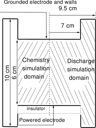
The axisymmetrical physical domain for plasma simulation is shown in figure 1. The chosen dimensions of reactor refer to the experimental setup [1]. The gas-phase chemistry simulation domain is also shown.
| Reaction | Energy threshold, eV | |
|---|---|---|
| Vibrational excitation | ||
| 1 | CH4 + e = CH + e | 0.162 |
| 2 | CH4 + e = CH + e | 0.361 |
| Dissociation | ||
| 3 | CH4 + e = CH3 + H + e | 8.0 |
| 4 | CH4 + e = CH2 + 2H + e | 8.0 |
| Ionization | ||
| 5 | CH4 + e = CH + 2e | 12.6 |
| 6 | CH4 + e = CH + H + 2e | 14.3 |
Table 1. Electron-methane reactions involved in Monte Carlo collisions simulation.
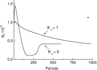
To accelerate the convergence of PIC-MCC simulation, the algorithm described in [27] was applied. The advantage of this method is illustrated in figure 2, where total number of ions in discharge volume during simulation is plotted versus number of simulated rf periods for two different values of acceleration factor KA (explained in [27]). The simulations were proceded for geometry shown in figure 1, pressure 50 mTorr and =80 V. It can be seen, that the convergence of simulation results is by nearly KA times faster, thus saving the computational amount by the same factor. In practice, KA factor is limited (usually to 5-7) because it strongly increases the statistical noise and oscillations of solution. Convergence usually required 500-3000 rf cycles, the larger value belongs to higher voltages and pressures. Simulation of 1000 rf cycles took about 40-60 hours on Pentium III 800 MHz.
3 Results of discharge simulations
Simulations were performed for discharge frequency 13.56 MHz in a cylindrical reactor with 14 cm diameter and 6 cm interelectrode spacing (figure 1) in pressure P range from 50 to 300 mTorr and rf voltage from 40 to 180 V.
The main information obtained was 2D distribution of plasma density and potential, mean electron energy and electron - methane reactions rates. Previous 1D simulations of rf methane plasma [15, 24] show that for some discharge parameters in the center of discharge gap, where electrons are trapped by the ambipolar electric field, accumulation of relatively cold electrons occurs. Hence the average electron energy in this region is much smaller than in electrode sheaths. In noble gases, this effect was also observed [28, 29]. In 1D simulations, electron energy in the sheaths may be several eV, and in center of discharge it may be one order of magnitude less. Hence, the electron - methane reactions strongly dominate in the sheaths region. We call this ”active-sheaths” (AS) discharge regime, in contrast to the another observed ”volume-dominated” (VD) regime, when electron energy has more uniform profile and electron - neutral reactions proceed in all reactor volume [24].
We observed the existence of these regimes also in 2D simulations and studied the transition between them for different discharge parameters. As an example, results of simulation for P=123 mTorr and = 120 V are presented in figure 3. The electron density, averaged over period (figure 3(a,d)), is asymmetrical with maximum shifted to powered electrode due to self–bias voltage (this was also observed in experiment [1] and predicted by 1D PIC-MCC simulation with artificial bias imposing in [14]). It is seen that electrons in the center of discharge gap are relatively cold (average energy is 0.75 eV while in sheaths it exceeds 2 eV), see figure 3(b) and also solid line in figure 3(e). This explains the behaviour of electrons reaction rates, which has steep maxima in regions with hot electrons. In figure 3(c) the 2D distributon of dissociation reaction rate CH CH3+H+ is shown. It is chosen for illustration as the main methane dissociation channel; the profiles of other dissociation and ionization rates have a similar form. It is seen, that the reaction proceeds in sheath regions and also at the outer reactor edge, and is suppressed (the rate falls by 2 orders of magnitude) in the most of discharge volume (see figure 3(c)). On the axial profile (solid curve in figure 3(f)), the absolute maximum of rate is located where maximum of electron energy coincides with large electron density; a second small maximum of rate corresponds to second maximum of energy but with lower plasma density. For 2D case, the difference of electron energy in center and in sheaths is not so large as in 1D simulations [15, 24], where it reaches one order of magnitude. This may be explained by influence of reactor edge region, where cold electrons are not trapped by electric field so strongly as in the 1D discharge geometry, and hence they may diffuse in radial direction, which leads to more flat spatial profile of electron energy.
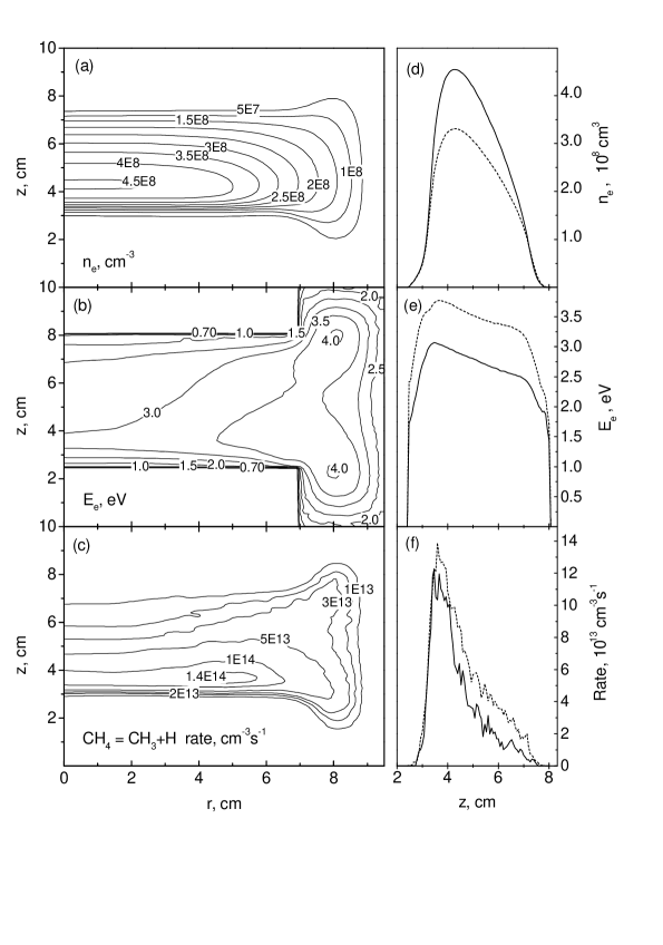
The described above case is an example of AS regime. Another discharge regime is shown in figure 4, obtained by simulation at P=50 mTorr and =60 V. Here we see a smooth profile of electron energy (figures 4(b) and 4(e)) and the reaction rate follows the electron density (see figure 4(c),4(f)). This corresponds to VD regime of discharge.
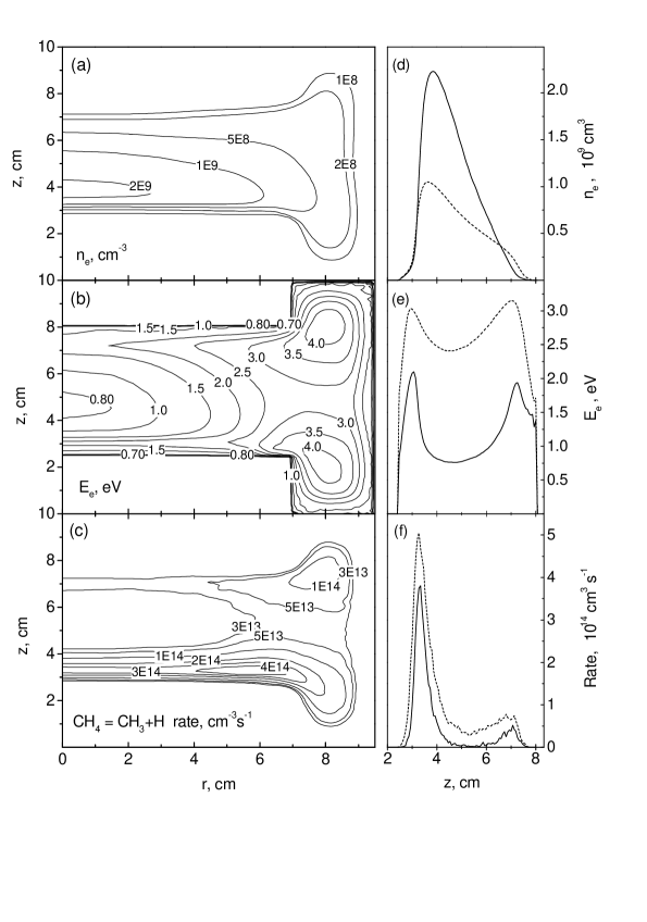
In general, for 2D simulations the discharge properties are radially uniform in the inner reactor area only (up to half of reactor radius). In AS regime, near reactor edge the vertical electron energy profile tends to be more uniform (dashed curve in figure 3(e)) and the reaction rate is not such strongly suppressed in gap center (dashed curve in figure 3(f)). Note that the average electron energy near edge is higher than in inner region, and although the plasma density gradually decreases towards the edge, the reaction rate even increases.
To investigate the transition between two regimes, we performed calculations with different rf voltages for pressures 50, 123 and 300 mTorr. The results are presented in 1D graphics, showing the period-averaged plasma parameters plotted along the reactor axis (for r=0).
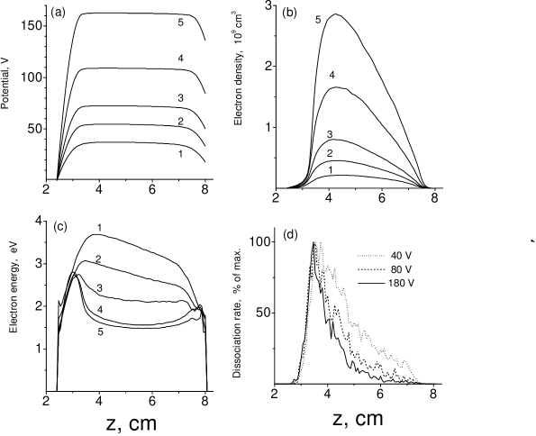
For the first case, P=50 mTorr, the obtained plasma potential, electron density, mean electron energy and CH CH3+H dissociation rate profiles are shown in figure 5(a-d) for several applied . It is seen in figure 5(a) that the potential drop in electrode sheaths is increasing with , and near the powered electrode (with zero time-averaged potential) it is few times larger than near the other one (its potential is equal to bias). The transition from VD to AS regime is noticeable in electron energy profiles. With increasing voltage, the energy decreases and for over 100 V an area with relatively cold electrons appears, making a valley on electron energy profile (figure 5(c)). A relatively large energy maximum appears in the sheath of powered electrode and a small one in the grounded sheath. It is interesting, that increasing of from 120 to 180 V change the energy profile very weak, while electron density still increase (figure 5(b)). The form of all density profiles is almost identical, with various scaling only. The maximun is slightly shifted to powered electrode due to self–bias voltage. The electron reactions rate profile is wide for low voltages, and narrows with voltage increasing (figure 5(d)), indicating that the electron reactions tend to localize in the sheath region. The statistical noise is clearly seen on the rate profiles, despite they are averaged over 100 recent rf cycles. To make picture readable, in figure 5(d) not all rate profiles are shown and the curves are plotted normalized to maximum value of each.
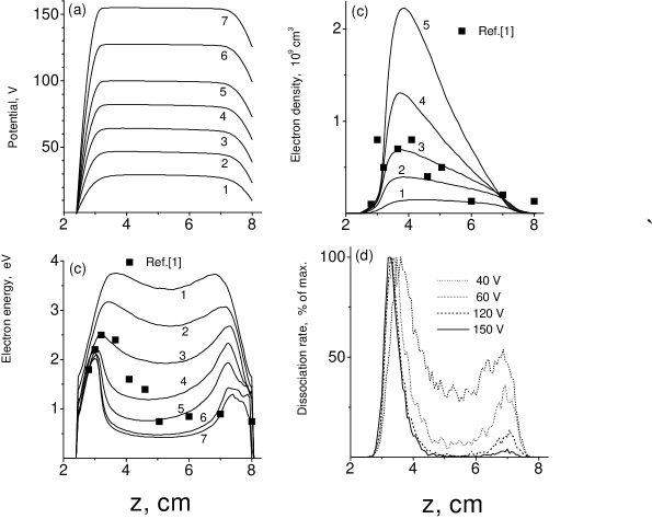
The results for P=123 mTorr are shown in figure 6. The transition from VD to AS regime is clearly seen here. For =40 V the central minimum of electron energy is hardly seen (curve 1 in figure 6(c)), but the regime is already transitional to AS, as can be seen from the reaction rate (40 V curve in figure 6(d)) - in the sheath near powered electrode it is 2-3 times larger than in the volume. With increasing, energy minimum becomes wider and deeper, making narrow maxima in both sheaths. Again the larger maximum is observed in powered electrode sheath. The second maximum near grounded electrode is better seen than for 50 mTorr, possibly due to larger potential drop in this sheath at higher pressure (compare figures 5(a) and 6(a)). The form of electron energy profile also tends to saturate for larger than 150 V, while the form of larger maximum becomes established near =100 V. Electron density increases with , as shown in figure 6(b). For 150 and 180 V it is not shown, but has the identical form as for 120 V, scaled to maximum 3.7 and 5.7 correspondingly. The position of density maximum shifts to the powered electrode (as observed in [1], shown by points in figure 6(b)) and for larger than 80 V does not move. The dissociation rate (figure 6(d)) exhibits two maxima near both sheath regions, with strong rate suppression in central region with increasing, thus indicating transition to the AS regime. Larger maximum corresponds to both energy and density maxima near powered electrode, with increase it strongly enlarges without broadening; the second maximum, near grounded electrode, is smaller and diminishes with increasing due to more cool electrons in this sheath. The points in figures 6(b,c) are taken from measurements made for P=123 mTorr in [1]. The best fitting with our simulations is obtained for =80 V, which is in agreement with discharge power 10 W in experiment [1].
Comparison with simulations of the same discharge parameters using fluid model [5] show good agreement in plasma potential profile (within a few V) and electron density (within 20%) but different electron energies, which were in [5] 3-4 eV in plasma bulk and near grounded electrode but increased to 11-13 eV in powered electrode sheath.
The last set of simulations was proceeded for P=300 mTorr (figure 7). For =60 V the regime is VD, with symmetrical plasma density profile and hardly noticeable minimum in energy profile (curve 1 at figures 7(b) and 7(c)) but enhanced reaction rates in sheaths (60 V curve in figure 7(d)). For =80 V, the regime is closer to AS (seen from the reaction rate profile, 80 V curve in figure 7(d)), the plasma density is one order of magnitude larger than for 60 V and asymmetrical (curve 2 in figure 7(b)), although the electron energy profile (curve 2 in figure 7(c)) does not exhibit a deep minimum.
With further increasing of , narrow energy maxima again appear in both sheaths, but unlike for the previous pressures, the maximum in grounded electrode sheath is larger than the other one. Such difference in energy profile evolution may possibly be explained by comparing plasma potential behavior (compare figures 6(a) and 7(a)). For 300 mTorr the potential drop in powered electrode sheath is by 16-18 V smaller than for 123 mTorr, while near the grounded one it is larger: for from 80 to 180 V the drop varies from 30 to 40 V instead of 23 to 28 V for 123 mTorr. Sheath thickness is nearly the same for both pressures (near 0.9 cm in AS-regime). Like for previous pressures, the energy profiles tends to saturate with voltage over 150 V.
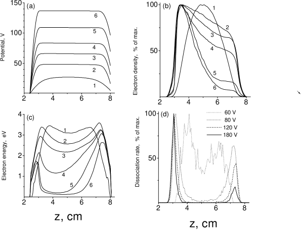
The behaviour of electron density is shown in figure 7(b). As it varies for more than two orders of magnitude, the profiles are also plotted normalized to maximal value of each. However, it can be seen from this graphics that VD-AS transition leads to accumulation of cold electrons in ampibolar field region, where plasma potential has a plateau.
4 Gas phase chemistry simulation
For simulation of gas phase chemistry, the balance equations for neutral species density were solved, where is the distance from the reactor axis (radial direction), is the distance from the powered electrode (axial direction). The physical domain for chemistry simulation is reduced to interelectrode space, as shown in figure 1. The convection is also taken into account:
is the sum of generation and loss for i-th species due to chemical reactions, is the flux, where is diffusivity, is the gas velocity in the plasma reactor, given as two-dimensional vector field.
The chemical model includes radicals H, CH, CH2, CH3, C2H5, and stable species H2, CH4, C2H2, C2H4, C2H6, C3H8. For balance equations of radicals, which have non-zero coefficient of sticking to the surface, the additional loss terms were included at the electrodes boundaries:
Where is radical density at the boundary, is thermal velocity and the value of was assumed to be 0.01 for all types of radicals except 0.025 for CH2 [11]. The diffusivities were taken as in [7] for radicals, and as in [11] for stable species.
| N | Reaction | Rate constant kN, | [Ref.] |
|---|---|---|---|
| Electron-methane | |||
| 1 | CH4 + e = CH3 + H + e | obtained by MCC | |
| 2 | CH4 + e = CH2 + 2H + e | obtained by MCC | |
| 3 | CH4 + e = CH + 2e | obtained by MCC | |
| 4 | CH4 + e = CH + H + 2e | obtained by MCC | |
| Ion-methane | |||
| 5 | CH4 + CH = CH + CH3 | 1.510-15 | [3] |
| 6 | CH4 + CH = C2H + H2 | 1.210-15 | [3] |
| Radical reactions | |||
| 7 | CH3 + CH3 = C2H6 | 8 10-17 | [6] |
| 8 | CH3 + H = CH4 | 1.3810-16 | [6] |
| 9 | CH2 + H = CH + H2 | 2.710-16 | [6] |
| 10 | CH2 + CH4 = CH3 + CH3 | 1.510-18 | fitted, see text |
| 11 | CH2 + CH2 = C2H2 + H2 | 5.310-17 | [6] |
| 12 | CH2 + CH3 = C2H4 + H | 10-16 | [6] |
| 13 | CH + CH4 = C2H4 + H | 10-16 | [11] |
| 14 | CH + CH4 = C2H5 | 10-16 | [11] |
| 15 | C2H5 + H = CH3 + CH3 | 610-17 | [11] |
| 16 | C2H5 + H = C2H4 + H2 | 310-18 | [11] |
| 17 | C2H5 + CH3 = C3H8 | 4.210-18 | [11] |
Table 2. Chemical reactions taken into account in gas phase chemistry model.
The set of gas phase chemical reactions was taken as in [6] with reactions responsible for C2H5 radical balance added from [11] (see table 2). The volume rates of electron - methane reactions are obtained in discharge simulation as two-dimensional profiles and used as production terms for corresponding species. The account of ion - methane reactions 5 and 6 requires the information about ion mixture composition, which is not considered in PIC-MCC simulations. However, preliminary calculations show that a simplification can be made to exclude the ion reactions from the chemical model. Since the rate constant of reactions 5 and 6 are high enough, estimation shows that CH and CH ions exist for a few free paths only before conversion to CH and C2H, which do not take part in gas phase chemistry. As each type of ion has the only one way of chemical conversion, the volume rate of reaction 5 can be assumed equal to those of 3. The same applies to reactions 6 and 4. So the reactions 3,5 and 4,6 may be combined and replaced by:
3,5: 2CH4 + e = CH + CH3 + 2e
4,6: 2CH4 + e = C2H + H2 + H + 2e
with the rates equal for those of reactions 3 and 4, respectively. Thus the effect of ion - methane reactions is accounted through their production rates and only neutral species remain in the chemical reactions system.
The rate constant of reaction 10, found in literature, ranged from = 10-20 [1] to 10-18 [6, 9] and 1.710-17 [3]. This rate constant strongly affects the solution for CH2 radical, because CH4 has the largest density and reaction 10 is the main loss term for CH2. For the other species its influence is weak. We used it as a fitting parameter, and found that the best agreement with experiment [2] is achieved for = 1.510-18 , which is close to used in [6] or [9].
To take into account the effect of convection, we considered reactor with gas inlet through the centre of reactor and outpumping at the outer boundary. For these model calculations the field of gas velocity was simplified:
where is the gas inlet radius (taken as 0.5 cm). Density of CH4 was held constant at in order to make a feed term in convection. The value of was defined to give a chosen time of gas residence in reactor, which was varied in calculations from = 15 ms to 300 ms. Although assuming to zero may be a rough approximation, especially for the central region, calculations show that the density profiles are not very sensitive to details of field in central region, but depend mostly on .
The balance equations are approximated using finite-difference scheme in cylindrical physical domain (see figure 1) and integrated on time by Runge-Kutta method until the solution converged to steady state. The densities of radicals converge fast, while solution for stables requires physical time of about 2.
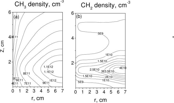
A typical result of two-dimensional gas phase chemistry simulation is presented in figures 8 and 9. The electron - methane reaction rates were taken for discharge at P=123 mTorr, = 80 V, was chosen as 150 ms.
Figure 8 show two-dimensional density profiles of the main radicals CH3 and CH2. As the discharge regime is close to AS, the density has maxima near electrode sheaths, where electron-methane reactions are localized (see figure 6(d)). Profile of CH3 is more flat due to its larger time of chemical decay.
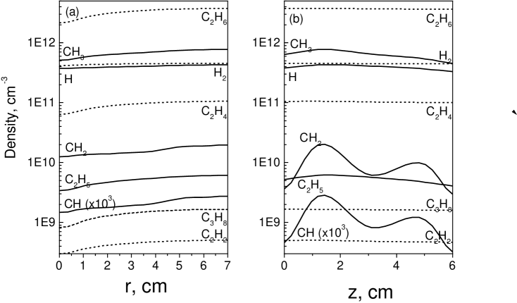
Figure 9(a) show the profiles in radial direction, plotted by solid lines for radicals, which profiles are shown at =1.2 cm, where radical density is maximal, and by dotted lines for stable species (their profiles are almost flat in axial direction). Figure 9(b) shows profiles of same species in axial direction at the outer edge of electrodes (=7 cm), where all densities are maximal. The profiles of CH, which has in our calculations density less than 107 , are enlarged by factor of 1000. For =150 ms, the most abundant stable C2H6 has maximal density 103 times less than methane (4.3 1015 ), so the neglecting of chemistry influence on discharge physics is possible.
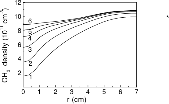
Calculations with various show, that the density profiles of stable species, which main loss term is convection, are approximately proportional to . For radicals, the profiles are determined also by diffusion and chemical decay, so for low gas velocities the influence of convection is weak. The effect of variation on CH3 density profile is shown in figure 10. The upper curve was obtained with zero convection term, when the steady state solution is achieved only for radicals. Of course our discharge simulation remains valid only for small enough (of 100 ms order of magnitude), while we can still neglect the change of gas composition, so this curve shows only the possible limit of convection influence.
It is seen, that the density saturates with increasing of , at first in the outer region, where gas velocity is smaller. For 100 ms it becomes saturated for the most part of reactor, so we usually made calculations with =150 ms (for our reactor geometry and P=123 mTorr this corresponds to gas feed rate of 55 sccm, which is close to used in experiments [1, 2]. The behaviour of H and C2H5 profiles is similar. For CH2 and CH, the profile is much less sensitive to , because the main loss term for them is the chemical decay.
5 Comparison with experiment
Calculations with various pressure were made to compare the profiles of CH3 and CH2 radicals with the observed in [2]. The simulated pressures were 300, 140, and 57 mTorr, the other conditions were the same as for figure 8. The results are presented in figure 11(a,b) for CH3 and figure 11(c,d) for CH2. Figure 11(a) shows CH3 profiles, plotted at = 4.5 cm, where they were measured in experiment [2], for pressures 140 and 300 mTorr. The agreement with experiment for P=140 mTorr is fine. Note that the only fitting parameter was the rate constant . For P=300 mTorr the profile exhibits two maxima, similar to experiment, but the calculated density is some larger, especially near the grounded electrode. Figure 11(c) shows the same for CH2. The agreement for 140 mTorr is good again, but profiles are more steep than in experiment, especially for 300 mTorr, where calculated density is very small in the centre of discharge gap. This may be caused by underestimation of the electron–methane reaction rates in the discharge center for high pressures. This shows that for pressures of 300 mTorr and higher the developed kinetic model is not very accurate. In figures 11(b) and 11(d) the both radical profiles are shown for 57 mTorr. Although the calculated profiles are more steep than the observed, the agreement can be considered as satisfactory.
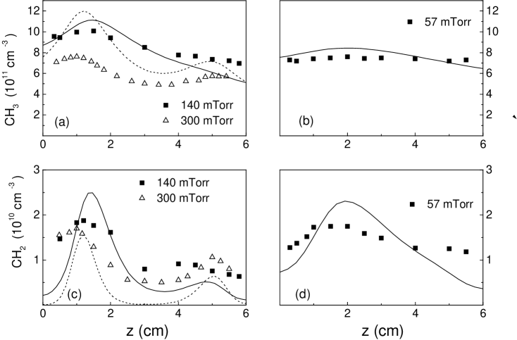
We can say the calculated profiles exhibit the similar behaviour as the observed in experiment. The shape of described in [2] density humps and transition to flat profiles with pressure decreasing are simulated well. We suppose that the appearance of density humps indicate the transition from VD to AS regimes, which is consistent with our simulations. The quantitative agreement is good in pressure range from 50 to 150 mTorr for both radicals, especially for CH3. Also for CH3 it is within 30% in range 50300 mTorr. As for CH2, the calculated densities in plasma bulk are underestimated for pressures larger than 150 mTorr.
6 Summary
Accelerated PIC-MCC method was applied to two-dimensional simulation of capacitively coupled radio frequency discharge in methane. The obtained spatial distributions of mean electron energy and electron–methane reaction rates show existence of two regimes of discharge glow. The first, with active sheaths, is characterized by hot electrons localized in electrode sheaths and relatively cold electrons in other discharge volume, hence the reactions proceed in electrode sheaths regions and are suppressed in the plasma bulk. For the case of the second one, with volume domination, the electron energy is more uniform and the reactions take place in all discharge volume.
The transition between discharge regimes for one–dimensional geometry was previously studied in [24] using combined PIC–MCC model. Unlike the 1D results, where the transition occurs abruptly at some critical current density, in 2D case transition is gradual, with continuous evolution of mean electron energy and reaction rates profiles. For the considered reactor geometry it was found, that the VD regime is observed for low rf voltages (40-60 V), and turns to AS with voltage increasing. The transition proceeds in range from 60 to 120 V and is noticed firstly at the spatial profile of electron–methane reaction rates. For over 120 V the regime is definitely AS. It was also noted, that the mean electron energy profile tends to saturate for over 150 V, and changes very little with further voltage increasing. For another reactor geometry the quantitative results may differ.
To find the gas mixture composition in discharge volume, simulations of chemical reactions in methane plasma were also performed, with the diffusion and convection flux of species included. The results show good agreement with the known experimental data, especially for pressure range from 50 to 150 mTorr. For more wide range to 300 mTorr, a qualitative agreement, namely the behaviour of radical density profiles shape, is obtained too.
Acknowledgments
This work was supported by NATO grant SfP-974354 ”SfP-Diamond deposition”.
References
- [1] Sugai H, Kojima H, Ishida A and Toyoda H 1990 Appl. Phys. Lett. 56 2616
- [2] Sugai H and Toyoda H 1992 J. Vac. Sci. Technol. A10 1193
- [3] Tachibana K, Nishida M, Harina H and Urano Y 1984 J. Phys. D: Appl. Phys. 17 1727
- [4] Bera K, Yi J W, Farouk B and Lee Y H 1999 Plasma Sources Sci. Technol. 8 412
- [5] Bera K, Yi J W, Farouk B and Lee Y H 1999 IEEE Trans. Plasma Sci. 27 1476
- [6] Bera K, Farouk B and Lee Y H 2001 Plasma Sources Sci. Technol. 10 211
- [7] Rhallabi A and Catherine Y 1991 IEEE Trans. Plasma Sci. 19 270
- [8] Gogolides E, Buteau C, Rhallabi A and Turban G 1994 J. Phys. D: Appl. Phys. 27 818
- [9] Gogolides E, Mary D, Rhallabi A and Turban G 1995 Japan. J. Appl. Phys. 34 261
- [10] Gogolides E 1997 Japan. J. Appl. Phys. 36 2435
- [11] Herrebout D, Bogaerts A, Yan M, Gijbels R, Goedheer W and Dekempeneer E 2001 J. Appl. Phys. 90 570
- [12] Herrebout D, Bogaerts A, Yan M, Gijbels R, Goedheer W and Vanhulsel A 2002 J. Appl. Phys. 92 2290
- [13] Birdsall C K 1991 IEEE Trans. Plasma Sci. 19 65
- [14] Nagayama K, Farouk B and Lee Y H 1998 IEEE Trans. Plasma Sci. 26 125
- [15] Ivanov V, Proshina O, Rakhimova T, Rakhimov A, Herrebout D and Bogaerts A 2002 J. Appl. Phys. 91 6296
- [16] Levitskii S M 1957 Sov. Phys. Tech. Phys. 2 887
- [17] Godyak V A, Piejak R B, and Alexandrovich B M 1992 Phys. Rev. Lett. 68 40
- [18] Godyak V A, and Piejak R B 1990 Phys. Rev. Lett. 65 996
- [19] Bohm C and Perrin J 1991 J. Phys. D: Appl. Phys. 24 865
- [20] Andujar J L, Bertran E, Canillas A, Roch C, and Morenza J L 1991 J. Vac. Sci. Technol. A9 2216
- [21] Parker G J, Hitchon W N G, and Lawler J E 1993 Physics of Fluids B 5 646
- [22] Belenguer P and Boeuf J P 1990 Phys. Rev. A 41 4447
- [23] Belenguer P and Boeuf J P 1992 J. Appl. Phys. 71 4751
- [24] Schweigert I V, submitted to Phys. Rev. Lett., 2004
- [25] de Urquijo J, Dominguez I, Alvarez I and Cisneros C 1997 J. Phys. B: At. Mol. Opt. Phys. 30 4395
- [26] de Urquijo J, Arriaga C A, Cisneros C and Alvarez I 1999 J. Phys. D: Appl. Phys. 32 41
- [27] Schweigert V A, Alexandrov A L, Gimelshein S F and Ivanov M S 1999 Plasma Sources Sci. Technol. 8 B1
- [28] Godyak V A, Piejak R B and Alexandrovich B M 1992 Plasma Sources Sci. Technol. 1 36
- [29] Berezhnoi S V, Kaganovich I D and Tsendin L D 1998 Plasma Phys. Rep. 24 556