Energy losses and efficiency of laser – electron X-ray generator for medical applications
Abstract
A source of medical x-rays based on a 50 Mev storage ring and a quasi-continues picosecond laser is considered. It is shown that such generator produces useful X-ray flux with higher average power and higher efficiency than that of conventional X-ray tubes. The main energy losses are related to coherent synchrotron radiation. Taking this into account the required parameters of the storage ring and injector are determined.
pacs:
87.59.Dj; 29.20.Dh; 52.59.Px; 41.50.+h;I Introduction
The experiments with synchrotron radiation sources confirmed that the use of narrowband X-ray beams extends substantially diagnostics capabilities in mammography, bronchography, angiography, computer tomography etc 1 - 3 . Apart from the image contrast improvement there are several other advantages of this method: possibility for subtraction of images taken at the wavelengths before and after absorption K-edge of the contrast element (usually iodine), reduction of radiation dose and amount of the contrast material, intravenous (catheterless) angiography of coronary arteries, etc. Actually new attractive methods of X-ray diagnostics are emerging.
However further development and practical applications of these methods depend on the availability of a compact (as compared with synchrotrons) narrowband X-ray source suitable for installation in medical centers and hospitals. As a rule it should work in the energy range 20 -50 kev that includes K absorption edges of the elements I and Gd used in contrast compounds.
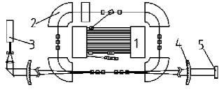
As a solution of the problem of narrowband compact X-ray source it was proposed to generate X-rays in collisions of a laser beam with an electron beam moving in opposite direction. In such an approach the electron beam energy decreases from several Gev (as for the systems based on synchrotrons with magnetic undulators) to tens Mev and the dimension of the device changes from tens of meters down to several meters. To produce electron beams for this purpose both storage rings 4 , 5 and linear accelerators 6 can be utilized. In this paper the energy losses and efficiency of X-ray generator based on a storage ring and repetitive laser is considered (see FIG. 1).
II Laser-electron X-ray generator (LEXG)
The X-ray photon flux required for coronary arteries subtraction angiography is estimated as:
| (1) |
at the surface of a human body 7 , 8 . The time necessary to obtain a single image must be 2-4 ms, and the frame rate: 20 30 s-1 9 .
In the electron rest frame the process of laser photon scattering by an electron is the classical Thompson scattering. The energy of the scattered (X-ray) photon in the laboratory frame is:
| (2) |
where is laser photon energy and , electron energy. The average X-ray photon flux caused by Thomson scattering is:
| (3) |
where is the number of electrons in the bunch; cm2, Thompson cross-section; , the laser photon flux; , the finesse of the optical cavity, which is used to enhance the power of the laser beam in the interaction region; and , the cross section areas of the electron and laser beams respectively. We assume that both laser and electron beams consist of bunches following with equal repetition rate and having equal cross-section areas /2 (see Appendix A).
Using (1), (3) it is easy to show that X-ray flux required by (1) can be attained with a system consisting of a storage ring, a laser and an optical cavity, which parameters are given in Table I. The listed parameters either have been already achieved or close to the achieved ones in existing setups 10 .
The electron bunch length in Table I was chosen equal to double Raleigh length of laser beam: assuming the Gaussian electron density distribution in transverse direction (see Appendix A). Then the storage ring emittance is 0.1 mmmrad.
Table I. Parameters of the LEXG.
Storage ring
Electron energy MeV
Relative energy
Bending radius m
Orbit circumference m
Revolution period ns
Number of electrons in bunch
Current A
Bunch length cm
Laser
Laser photon energy eV
Repetition frequency MHz
Laser beam cross section area cm2
The laser pulse energy m
The average laser power W
The laser pulse duration ps
Cavity
Finesse
The energy of the laser pulse in the cavity mJ
In the next sections we estimate the electron beam energy losses and the X-ray generator efficiency.
III The synchrotron radiation losses
The main source of electron energy losses in our storage ring (see Table I) is coherent synchrotron radiation (CSR), which spectrum lies in the microwave region. The CSR power for a bunch with Gaussian longitudinal charge density distribution can be estimated as (see Appendix A):
| (4) |
where = 2.810-13cm, is the perimeter of the electron orbit.
Substituting the values from Table I for the LESG into (2) and also supposing we obtain:
| (5) |
where is the energy lost by an electron in one revolution. This energy loss is compensated by the storage ring radio frequency (RF) cavity. The accelerating voltage there should not be less than U=250 kV in order to provide the stability of the electron bunch (see Appendix B). In the next section the storage ring power consumption is estimated.
IV Storage ring and injector
As an injector for the storage ring it is reasonable to take a compact highly efficient race-track microtron with photo-cathode electron gun 11 . To simplify storage ring operation the injection energy should be close to the final energy of the stored electrons. To store 1 nC charge in a single ring bunch multi-turn injection can be used with the injector operating in single bunch mode with 100-150 pC bunch charge and bunch repetition frequency dependent on the ring damping time. The use of rare-earth permanent magnets in the injector and storage ring design will essentially decrease energy consumption.
In the storage ring with permanent magnets the required electric power is defined mainly by an RF power necessary to produce the accelerating structure voltage inside the accelerating structure (single RF cavity or a chain of coupled cavities):
| (6) |
where is the effective shunt impedance and is the structure’s electrical length. Because of , where is operating frequency, for a fixed structure length the RF power required decreases with frequency increase. Some aspects of storage ring beam dynamics are also favorable to higher frequency. Other considerations, in particular the separatrix size, the cavity beam hole aperture favors lower frequency. The final choice hasn’t been made yet, so two possibilities were considered: 2856 MHz – equal to the injector operating frequency 11 , and 571.2 MHz – the fifth subharmonic. Consider elliptical form cavity, which has 1.5-2 times lower shunt impedance as compared with the optimized cavity, but is more stable with respect to multipactor discharge and parasitic modes excitation. With such a cavity one obtains 30 M/m and 8 kW for = 0.2625 m (five half wavelength coupled cavities chain) at 2856 MHz, and 13.4 M/m, 18 kW for the single cavity of the same length at 571.2 MHz. The RF power dissipated per unit length in the considered cases is 30 kW/m and 69 kW/m, respectively. These thermal loads will not change essentially structure parameters if the cooling channels are properly constructed. Taking into account beam loading and RF amplifier efficiency, the full power consumption from the socket will be about 20 and 40 kW, respectively.
V The source of the optical radiation and its efficiency
Power consumption of optical unit of LEXG can be an order of magnitude less than that required for RF system if a solid state laser with diode pumping is used. Such lasers reached tens of percent efficiency during last decade. For example, in [12] the efficiency 28% is reported for Nd:YAG laser having quasi-continuous output with average power more than 300 W. The active element was 6 mm diameter and 50 mm length cylinder pumped by six high power diode bars.
Besides of efficiency, the stability of laser radiation is one more important parameter for LEXG. The enhancement of laser light power inside high finesse optical resonator implies both equal repetition rates and careful phase matching of laser and resonator pulses. In other words the most part of every laser mode energy must be concentrated inside the bandwidth of the corresponding resonator mode,, where is the length of the cavity. From this point of view optically pumped solid state lasers generating subpicosecond- and femtosecond pulses again have evident advantages [13]. For example, crystalline active mediums doped with ytterbium are successfully utilized for continues sequences of powerful subpicosecond pulses production. In [14] the average power of 60 W was obtained in a Yb:YAG laser with the duration of a single pulse 0.81 ps, and optical power of a linier diode assembly being 370 W. Estimated efficiency is not less than 5%.
A significant decrease of the optical source average power can be achieved with the transition from quasi-continues ultrashort pulse sequence to generation of pulse trains with train duration 2-4 ms corresponding to accumulation time of one X-ray image and with train repetition rate being 20-30 Hz. Such mode of operation can be reached using external negative feed-back loop 10 .
Thus from the above discussion it follows that the power necessary to feed the optical unit of LEXG is less than 2-3 kW.
VI Discussion
Estimations given in sections 4 and 5 show that for production of 1 W (see (1)) of X-ray radiation with photon energy kev a laser-electron X-ray generator with electrical power consumption 25-45 kW is required. In respect of efficiency (the ratio of useful X-ray flux to electric power consumption) LEXG surpasses X-ray tubes. Note that medical X-ray tubes utilized in angiography have power up to 100 kW 9 , 15 , 16 . No doubts that if physical and technical problems connected with the development of LEXG are resolved such X-ray sources will find wide application in medicine and other fields.
Except the scheme shown in figure 1 there are other possibilities to increase the coupling of electron and laser beams in order to provide necessary X-ray flux. For instance high-energy laser pulse circulation obtained by switching of a Pockel’s cell inside the optical resonator may be used [17]. The practical optical scheme should satisfy several conditions: resistance of the mirrors and other optical elements to laser and X-ray radiation loading, synchronization of laser pulses with electron bunches, time and phase matching of optical resonator with the laser beam etc. This will require special research.
VII Conclusion
A new X-ray generator for medical applications can be designed on the basis of a storage ring with electron energy 50 Mev and a picosecond laser. If high finesse optical resonator is used the plug efficiency of such a generator can be higher than that of conventional X-ray tubes. Other advantages of LEXG as compared to X-ray tubes are: narrowband X-ray beam, the absence of high energy “tail” in photon spectrum, the possibility of fine tuning of X-ray photons energy by changing the electron energy, image quality improvement by subtraction of images taken at different wavelengths near iodine K absorption edge, reduction of the necessary quantity of contrast materials and radiation dose received by a patient and medical staff, opportunity of catheterless angiography introduction into the wide medical practice.
Thus, a compact laser-electron X-ray generator can be considered as a promising direction of accelerator, laser and optical technology development.
Appendix A
Derivation of formula (3) assumed Gaussian radial density distribution of electrons and photons:
| (7) |
where is the mean square transversal beam size connected with the effective area of the cross section as . In the longitudinal direction the mean square transversal laser beam size changes in accordance with formula:
| (8) |
where is the Raleigh length.
The mean square transversal size of the electron beam is governed by the same law. The role of Raleigh length in this case plays the -function at the central point of interaction of laser and electron beams. The focal beam size is determined by the expression , where is the emittance of the electron beam.
Formula (2) for coherent synchrotron radiation losses was obtained by L.Schiff in 1946 18 . Similar formulas were derived in 19 - 21 . However numerical coefficients there are respectively 21.12, 275.04 and 26.35 times more than in (2). The analysis made by E.G. Bessonov and R.M. Fechtchenko 22 supported the results of L.Schiff.
Appendix B
Balance of energy gained by an electron in the RF cavity and lost due to synchrotron radiation and Thomson scattering defines an equation for electron phase oscillations in the storage ring 23 , 24 :
| (9) |
| (10) |
where ki is the exponent in the energy dependence of incoherent losses; , the total energy losses due to incoherent synchrotron radiation and Thomson scattering; , the energy losses for coherent synchrotron radiation; ; the revolution frequency (which is supposed to be equal to the laser repetition rate); , the momentum compaction factor; , the particle phase in the center of the bunch; the rest parameters were defined above. Equations (9), (10) determine conditions for bunch stability in the storage ring.
Incoherent synchrotron radiation and Thomson scattering provide slow damping of the phase oscillations and can be neglected in the first approximation. Coherent synchrotron radiation force acting on the electrons enlarges the bunch length [20]. The stability criteria in terms of equation (9) are provided by relation kept in the vicinity of phase , occupied by bunch electrons. Using equation for coherent synchrotron radiation power 20 we obtain:
| (11) |
Under this condition electron trajectories stay stable in spite of destabilizing role of coherent synchrotron radiation.
Substituting =10, and other parameters from the Table I into (11) we get 120 kV. In order the coherent synchrotron radiation would not change essentially equilibrium bunch dimensions this inequality must be fulfilled with some spare. More details for electron beam dynamics in the coherent synchrotron radiation field can be found in 22 .
References
- (1) B.Jacobsen, Acta Radiol., 39, 437 (1953).
- (2) E.Rubinstein et.al., Proc. SPIE, 314, 42 (1981).
- (3) M.Ando and C.Uyama (Eds.), Medical application of synchrotron radiation (Springer-Verlag, 1998).
- (4) R. Tatchyn, Remarks on the role of multilayer optics and short period insertion devices for medical imaging sources and application (see[3], pp139-148).
- (5) Zhirong Huang and R.D.Ruth, Phys. Rev. Lett., 80, 976 (1998).
- (6) F.E.Carrol, AJR, 187, 1197 (2003).
- (7) T.Dill, Synchrotron Radiation News, 11, N2, 12 (1998).
- (8) Y. Sugishita, Medical activities of synchrotron radiation in Japan – Intravenous coronary angiography, (see [3], pp 15-21).
- (9) A.M.Babunachvili, V.A.Ivanov, S.A. Biryukov and Stenting of Coronary Arteries, (ACB-Publishing, Moscow, 1996) (in Russian).
- (10) E.G.Bessonov, et al, Physics-Uspekhi, 46, 872 (2003).
- (11) A.S. Alimov, et al, NIM B, 139, 511 (1998).
- (12) S. Fujikawa, K. Furuta, and K. Yasui, Optics Letters, 26, 602 (2001).
- (13) P.G.Kryukov, Quantum Electronics, 31, 95 (2001).
- (14) E.Innerhofer, et.al., Optics Letters, 28, 367 (2003).
- (15) N.N.Blinov (ed.), Principles of X-ray Diagnostics Technology (Medicine, Moscow, 2002) (in Russian).
- (16) A.M.Babunachvili, I.Kh.Rabkin and V.A.Ivanov, Coronary Angioplasty (ACB-Publishing, Moscow, 1996) (in Russian).
-
(17)
M. Uesaka, A. Fukasawa (Tokyo Univ.), K. Dobashi, H. Iijima (NIRS),
J. Urakawa, T. Higo, M. Akemoto, H. Hayano (KEK), X-band RF Gun/Linac
for Inverse Compton Scattering Hard X-ray Source, Proc. of The XXI
International Linac Conference Gyeongju, Korea, Auguest 19 - 23, 2002
(Web site: http://linac2002.postech.ac.kr/). - (18) L.Schiff, Rev. Sci. Instr., 17, 7 (1946).
- (19) J.S.Nodvic and D.S.Saxon, Phys. Rev., 96, 180 (1954).
- (20) L.V.Iogansen and M.S.Rabinovich, JETP, 37, 118, (1959) (in Russian).
- (21) E.L.Saldin, E.A.Schneidmiller and M.V.Yurkov, TESLA FEL Report 96-14, November 1996.
- (22) E.G.Bessonov, R.M.Fetchenko and V.I.Shvedunov, physics/0404141.
- (23) A.A.Kolomensky and A.N.Lebedev, Theory of Cyclic Accelerators (North Holland Publishing, 1966).
- (24) H Wiedemann, Particle Accelerator Physics (Springer Verlag, New York, 1993).