Charge Transfer and Charge Broadening
of GEM Structures in High Magnetic Fields
Abstract
We report on measurements of charge transfer in GEM structures in high magnetic fields. These were performed in the framework of the R&D work for a Time Projection Chamber at a future Linear Collider. A small test chamber has been installed into the aperture of a superconducting magnet with the GEM structures mounted perpendicular to the B field direction. The charge transfer is derived from the electrical currents monitored during irradiation with an 55Fe source. No severe loss of primary ionisation charge is observed, but an improved ion feedback suppression is achieved for high magnetic fields. Additionally, the width of the charge cloud released by individual 55Fe photons is measured using a finely segmented strip readout after the triple GEM structure. Charge widths between 0.3 and 0.5 mm RMS are observed, which originate from the charge broadening inside the GEM readout. This charge broadening is only partly suppressed at high magnetic fields.
keywords:
Time Projection Chamber, TPC; Gas Electron Multiplier, GEM; Ion Feedback; Electron Transparency; Spatial ResolutionPACS:
29.40.Cs, 29.40.GxPITHA 04/01
, , , , , , , ,
1 Introduction
A Time Projection Chamber (TPC) is foreseen as the main tracker of the detector for a Linear Collider such as TESLA [1]. Currently the possibility to use Gas Electron Multipliers (GEM) [2] for the charge amplifying system is studied extensively. When using GEMs for the TPC end plate, the pads directly detect the amplified electron cloud which results in a fast and narrow charge signal. The fine structures of the GEM of the order of 100 m size allow the detection of the charge cloud with high spatial resolution. In contrast to wires, a GEM shows no preferred direction, thus any effects will be isotropic. Finally, using different electric fields on both GEM sides, the drift of ions produced inside the GEM holes into the TPC drift volume (ion feedback) can be suppressed and the need of a gating grid can be potentially avoided.
To demonstrate the advantages of a TPC with GEM readout, a prototype chamber will be built within the R&D activities of the Linear Collider TPC group [3, 4] resembling a sector of the TPC as in the TDR design. It will be operated in test beams and in magnetic fields up to 5 T. The end plates of this prototype will contain up to three planes of charge amplifying GEM foils. The operation conditions of this multi-GEM-structure have to be studied beforehand, because in the case of three GEM planes six electric fields have to be set. For these studies two small test chambers were set up at RWTH Aachen and installed in a 5 T magnet at DESY Hamburg. The first chamber was dedicated to the measurement of charge transfer in high magnetic field and the second one to the determination of the transverse charge spread as a function of the magnetic field.
2 Experimental Setup
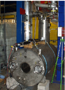
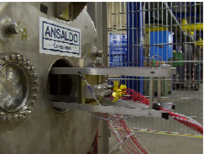
The measurements described below were accomplished in a 5 T superconducting magnet at DESY (see Figure 1). After formerly serving as magnet compensating the main field of the ZEUS experiment, the solenoid has been reinstalled in the cryogenic plant of the HERA accelerator at DESY to provide a high magnetic field facility for detector R&D projects for a future Linear Collider such as TESLA.
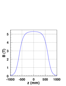
The magnet has an aperture of 28 cm and a coil length of 120 cm. Including its cryostat, the total length amounts to 186 cm. The coil is cooled by 4.5 K liquid helium to ensure superconductivity. The solenoid is operated at currents up to 1000 A corresponding to a central magnetic field of up to 5.3 T as shown in Figure 1. With the ramp rate of 0.5 , it takes about half an hour to ramp up the magnet from 0 T to 5.3 T. More detailed information on the magnet facility is presented in [5].
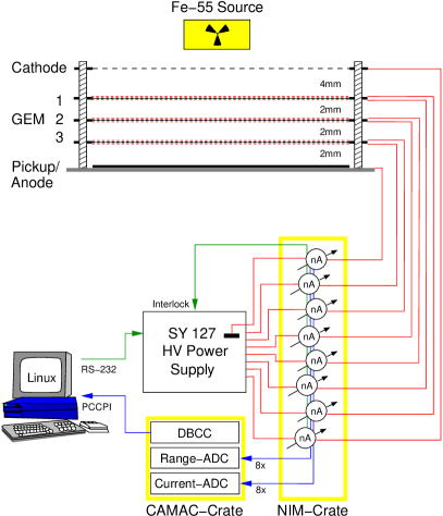
The mechanical and electric setup of our test chambers has been described in detail in Reference [6]. The gas volume consists of a composite frame enclosing a stack of three standard GEM foils. Using thin absorbers the radiation from an 55Fe source of 1 GBq activity is diminished such that about photons per second reach the chamber. A small window on top of the chamber covered by a 24 m thick mylar foil allows the photons to penetrate into the chamber.
The chambers were operated with a gas mixture as it is proposed in the TESLA technical design report [1] which consists of Ar(93%),CH4(5%),CO2(2%). A regulation system was used to keep the absolute pressure of the chamber at a constant value within 1 mbar. In addition the chamber’s temperature was continuously monitored and recorded. Each electrode (GEM surfaces and cathode) is connected to an individual channel of a CAEN SY127 HV power supply.
For the current measurements the anode plane consists of a solid copper electrode of the same size as the GEM structures [7]. Current monitors with a resolution of about 0.1 nA are inserted into the supply line of each HV channel. To measure the anode current, the anode plane is connected to ground via an additional current monitor. The high voltage control and current readout are handled by a custom application running on a Linux PC.
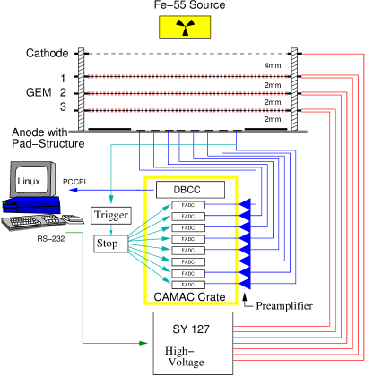
For the measurement of individual pulses an anode with a finely segmented area with 8 strips of 0.8 mm pitch is used [8]. The signal pulse of each strip is read out via a preamplifier and digitised using a 100 MHz Flash ADC. The eight FADCs digitise their input signal continuously and store it into a ring-buffer memory. After arrival of a trigger all FADCs are stopped and the memory is read out by a Linux computer. A trigger is generated if one of the strip signals exceeds the level of an analog discriminator.
In Figure 2 an overview of the electric setup and read-out system of the two test chambers is given. Figure 3 shows one of the chambers just before insertion into the aperture of the superconducting magnet.

3 Measurement of Charge Transfer in High Magnetic Fields
Our primary motivation for making tests in a magnet was to investigate whether there is a significant drop in collection efficiency for GEMs in high B-fields parallel to the electric field as suggested by the Langevin formula
| (1) |
where and are unit vectors of the fields, is the mean time between two collisions of the drifting electron, and is the cyclotron frequency. The last term proportional to , which gives the contribution along the magnetic field lines, could cause a drop in collection efficiency for high magnetic fields. When this term dominates, most electrons will no longer be collected into a GEM hole, but stay on drift lines perpendicular to the GEM surface and eventually reach the GEM’s copper coating. Those charges would be lost for the signal and consequently decrease the chamber’s capabilities due to the loss in primary ionisation statistics.
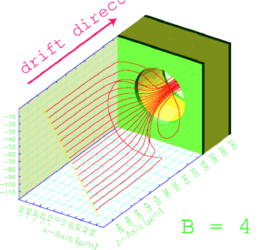
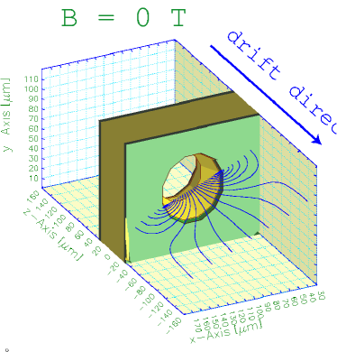
Figure 5 shows a numerical simulation using the programs MAXWELL [9], MAGBOLTZ [10] and GARFIELD [11]. In total 20 drift lines of electrons starting in front of a GEM hole are shown for a 4 T magnetic field perpendicular to the GEM surface. None of the drift lines end up on top of the GEM, but all electrons are collected into the GEM hole along curling tracks. From these simulations no significant drop in collection efficiency is expected in high magnetic fields. On the other hand the numerical simulations predict an increase in extraction efficiency. The situation is shown in Figure 5, where the drift lines of electrons out of a GEM hole at 0 T and at 4 T magnetic field are compared. In both simulations the same number of electrons start within the GEM hole. From the number of extracted drift lines one observes that more of the electrons are extracted at 4 T. This is explained by the third term in Equation 1 which is bending the drift lines along the B field direction.
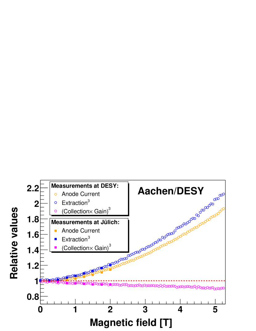
In Figure 7 the measured anode current as function of the magnetic field is shown. Measurements done in a 2 T magnet at the Forschungszentrum Jülich [6] are nicely reproduced by our new measurements at the 5 T magnet at DESY. It rises approximately by a factor of 2 between 0 T and 5 T. Simultanously the extraction efficiency of the electrons out of the last GEM in front of the anode plane was measured. Because the chamber was operated with a symmetric setup (all GEM voltages and electric fields at the same value) the increase of the anode current can be calculated from the product of collection efficiency, gain and extraction efficiency of a single GEM to the power of three. The independently measured extraction efficiency can explain the rise in the anode current. This shows that the product of collection efficiency and gain is only slightly affected by the change of the magnetic field. We see no indication for severe losses of primary ionisation charge.
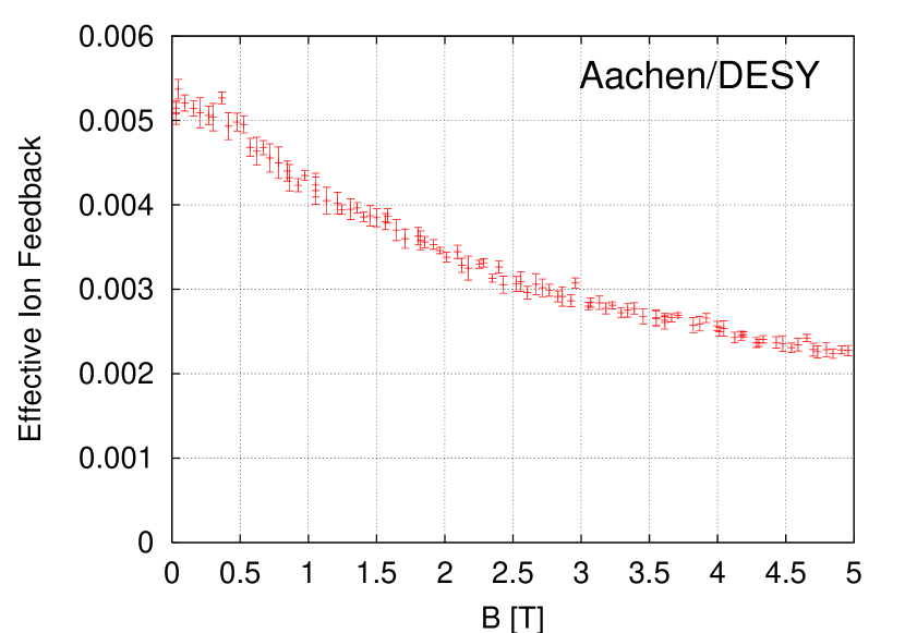
One important charge transfer quantity is the ion feedback, which describes how much ion charge is transferred into the drift volume per electron charge collected on the anode plane. Ions reaching the TPC drift volume would represent a positive space charge and deteriorate the electric drift field. The ion feedback can be derived from the measurements by dividing the cathode current by the anode current. Highly asymmetric electric fields on both sides of a GEM lead to ion suppression. The small electric field in the drift volume for example causes many of the drift lines from the amplification region inside the GEM hole to end on the copper plane facing the TPC drift volume.
Therefore, the relatively small drift field typical of a TPC automatically leads to ion feedback suppression. Moreover, the ion feedback can be minimised by the variation of the electrical fields within the GEM structure [12]. We searched for a setting with optimum ion feedback suppression with the drift field constrained at 200 V/cm and requiring an effective gain of . The first two GEMs are set at voltages of 310 V, the last GEM at 350 V. The first transfer field and induction field are set very high (6000 V/cm and 8000 V/cm respectively) whereas the second transfer field is set rather low (60 V/cm). Using this optimised setting allows a long term and stable operation of a triple-GEM structure with ion feedback well below 1%. The ion feedback is then measured as a function of the magnetic field. The result is presented in Figure 7 and shows that the ion feedback is further reduced with increasing magnetic field strength. This is due to the improved electron extraction already mentioned before. In a magnetic field of 4 T an ion feedback of only 2.5 permille has been achieved.
4 Dependence of Charge Width on the Magnetic Field
The information on the charge spread within a GEM structure is important to estimate the optimum pad size for the GEM TPC. The spatial resolution of a TPC improves with a magnetic field parallel to the electric field, because the transverse diffusion of the electron cloud is suppressed. A very narrow primary charge cloud, for example 300 m in Ar(95%):CF4(5%) at 4 T after a drift distance of 2.5 m, will reach the GEM readout structure. Then the charge cloud is further broadened by effects within and between the GEM foils. Possible effects are the gas amplification, highly divergent electrical field lines and the diffusion within high electric fields. The part of the charge broadening which is caused by diffusion effects can be reduced in high magnetic fields. We present new measurements of the charge spread by GEM structures in high magnetic fields.
The cluster width distribution for individual events has been analysed using a segmented pad anode. Only events of the photo peak, where the total photon energy has been deposited inside the chamber, are used for this analysis. In these events the 6 keV photon of the 55Fe source is converted into a 3 keV photo-electron, which is predominantly emitted perpendicular to the incoming photon. Additionally, a 3 keV Auger electron is emitted from the excited argon ion. The two electrons ionise the gas along their tracks and a primary charge cloud is produced. The primary charge cloud reaches the GEM structure after a maximum drift distance of 4 mm. Then the width of the charge cloud is further broadened inside the GEM structure.
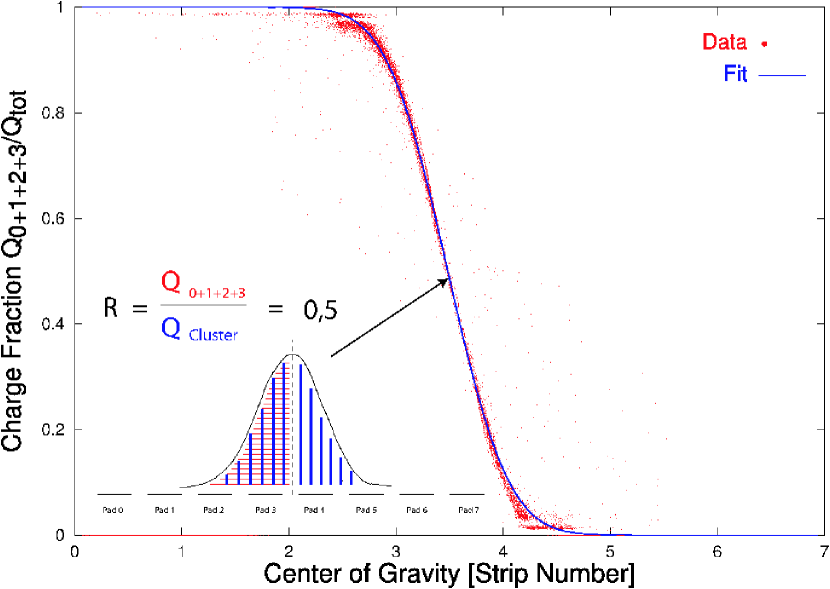
In this experiment the width of the charge cloud is determined from the charge sharing between adjacent strips. First the centre of the charge cloud is calculated from the centre of gravity of the measured signals on each of the eight strips. The charge sum measured on the left half of the anode (strips 0–3) is compared to the charge sum on the right side (strips 4–7). The charge ratio,
| (2) |
is calculated for each event. This ratio is then plotted versus the charge centre in Figure 9. As result one observes the typical shape of an error function as expected for a charge cloud of gaussian shape. From the slope of the data points one determines the width of the charge distribution. The charge width of the primary ionisation cloud is estimated to be in the range of 30–70 m, depending on the B field, and can therefore be neglected.
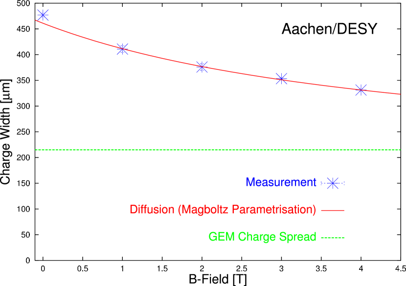
The result of the cluster width measurement is shown in Figure 9. The RMS width of the charge cloud is reduced from 0.5 mm without magnetic field to 0.3 mm at 4 T. From a numerical simulation using the program MAGBOLTZ we would expect a charge width between 400 m at 0 T and 240 m at 4 T due to the diffusion in the high transfer fields between the GEM foils. If we add a B-field independent charge broadening effect of the GEM structure of 215 m size quadratically, measurement and simulation agree.
5 Conclusions
The charge transfer and the charge broadening of triple-GEM structures have been studied in magnetic fields up to 5 T perpendicular to the GEM surface. With increasing magnetic field, an improved electron extraction efficiency has been measured, leading to a reduction of ion feedback by a factor of 2. No indication for a large drop in electron collection efficiency has been observed. The charge broadening of GEM structures has been measured and we conclude that the charge broadening nature of a triple GEM structure is not severely diminished by magnetic fields up to 4 T.
6 Acknowledgements
We thank the CERN printed-circuits workshop and R. Oliveira for providing the GEM foils. Those of us from RWTH Aachen thank DESY for its hospitality. We acknowledge the financial support of this R&D project by the German Bundesministerium für Bildung und Forschung.
References
-
[1]
TESLA Technical Design Report, Part IV,
DESY-01-011, ECFA 2001-209 (2001).
http://tesla.desy.de/new_pages/TDR_CD/start.html - [2] F. Sauli, Nucl. Instr. and Meth. A 386 (1997) 531.
- [3] The LC TPC group, DESY-PRC R&D 01/03.
- [4] The LC TPC group, A TPC for a Future Linear Collider, LC-DET-2002-008.
- [5] E. Gadwinkel et. al., Cryogenics for a 5 Tesla Superconducting Solenoid with Large Aperture at DESY, Proceedings of Cryogenic Engineering Conference CEC 2003, Anchorage, Alaska, USA, to be published in Advances in Cryogenic Engineering.
- [6] M. Killenberg et al., Nucl. Instr. and Meth. A 498 (2003) 369.
-
[7]
S. Lotze, ‘‘Aufbau eines Teststandes und Messungen zum Betrieb einer TPC mit GEMs’’,
diploma thesis RWTH Aachen (2001); available at
http://www.physik.rwth-aachen.de/group/IIIphys/TESLA/ . -
[8]
A. Münnich, ‘‘Experimentelle Untersuchung von GEM-Auslesestrukturen für eine TPC’’,
diploma thesis RWTH Aachen (2003); available at
http://www.physik.rwth-aachen.de/group/IIIphys/TESLA/ . - [9] MAXWELL, Commercial Finite Element Computation Package, Ansoft Co. Pittsburg, PA, USA.
- [10] S.F. Biagi, Nucl. Instr. and Meth. A 283 (1989) 716.
- [11] R. Veenhof, Nucl. Instr. and Meth. A 419 (1998) 726.
- [12] S. Blatt et al., ‘‘Minimisation of Ion Feedback in Multiple-GEM Structures’’, in preparation.