Space charge in drift chambers operated with the Xe,CO2(15%) mixture
Abstract
Using prototype modules of the ALICE Transition Radiation Detector we investigate space charge effects and the dependence of the pion rejection performance on the incident angle of the ionizing particle. The average pulse height distributions in the drift chambers operated with the Xe,CO2(15%) mixture provide quantitative information on the gas gain reduction due to space charge accumulating during the drift of the primary ionization. Our results demonstrate that the pion rejection performance of a TRD is better for tracks which are not at normal incidence to the anode wires. We present detailed simulations of detector signals, which reproduce the measurements and lend strong support to our interpretation of the measurements in terms of space charge effects.
keywords:
drift chambers , pulse height measurements , space charge , transition radiation detector , electron/pion identification, , , , , , , , , , , , , , , , , , , , , , , , , , , , , , , , , , , , , ,
for the ALICE Collaboration
1 Introduction
The ALICE Transition Radiation Detector (TRD) [1] is designed to provide electron identification and particle tracking in the high-multiplicity environment of Pb+Pb collisions at the LHC. To achieve the challenging goals of the detector, accurate pulse height measurement in the drift chambers operated with a Xe,CO2(15%) gas mixture over the full drift time of the order of 2 s is a necessary requirement. For such precision measurements, it is of particular importance first to collect [2], and then to properly amplify all the charge created in the detector. For electrons, the transition radiation, superimposed on the ionization charge, provides the required electron/pion identification capability.
For any detector with gas amplification, the positive ions created in the avalanche move slowly away from the anode, and this space charge leads to a local reduction of the electric field in the proximity of the anode. The effect was recognized in the early days of the development of proportional counters and was studied quantitatively later on [3, 4]. In case of multi-wire proportional drift chambers, the space charge was also studied in detail [5, 6, 7, 8], as was, more recently, done for electromagnetic calorimeters [9]. Several theoretical treatments of the problem have been published [3, 10, 11]. All of the previous studies concentrated on the resulting gain drop of the detector, with its associated loss of efficiency [5], as a function of the rate of incoming radiation. Recently, the effect of space charge on the position resolution of drift tubes was also investigated [12, 13].
The most obvious impediment caused by space charge concerns the high-rate performance of drift chambers (and gaseous detectors in general). However, space charge can also influence the signal amplitude within a single track [5, 8, 14]. For usual field values applied in multi-wire drift chambers, it takes several s for the positive ions to move away from the anode surface to a distance of several tens of the wire radius [15], where their effect on the anode field may be considered negligible. Since in usual drift chambers the arrival time of the primary electrons is also of the order of microseconds, the signal will be affected by the space charge created by the amplification of primary electrons over the full signal collection time (track length). As noted earlier [5], the effect is most pronounced for tracks at normal incidence to the anode wires, for which all charge collection takes place in a very confined region on the anode wire. The dimension of an avalanche created by one electron is below 100 m, essentially independent of its total charge [16]. The most significant contribution to the extension of the avalanche for a cluster of electrons is in fact the spread of the initial ionization due to transverse diffusion, which is, for instance, 440 m FWHM for 1 cm drift in our detectors.
We report on measurements of space charge effects within a single track in drift chambers operated with the Xe,CO2(15%) gas mixture. The measurements were performed during prototype tests for the ALICE TRD. The experimental setup and method of data analysis are described in the next section. We then present our measurements of the average pulse height dependence on drift time as a function of incident angle and gas gain. The implications of space charge on electron/pion identification are discussed. The measurements are compared to simulations, which strongly support our interpretation of the results in terms of space charge effects.
2 Experimental setup
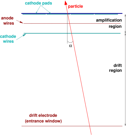
The results are obtained using prototype drift chambers (DC) with a construction similar to that anticipated for the final ALICE TRD [1], but with a smaller active area (2532 cm2). In Fig. 2 we present a schematic view of the DC. As the final detectors for ALICE TRD [1], our prototypes have a drift region of 30 mm and an amplification region of 7 mm. Anode wires (W-Au) of 20 m diameter are used, with a pitch of 5 mm. The cathode wires (Cu-Be) have 75 m diameter and a pitch of 2.5 mm, in a staggered geometry. We read out the signal on a segmented cathode plane with rectangular pads of 8 cm length and 0.75 cm width (along the direction of the wires). The entrance window (25 m aluminized Kapton) simultaneously serves as gas barrier and as drift electrode. We operate the drift chambers with the standard gas mixture for the TRD, Xe,CO2(15%), at atmospheric pressure. The gas is recirculated using a dedicated gas system.
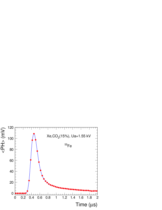
We use a prototype of the charge-sensitive preamplifier/shaper (PASA) especially designed and built for the TRD in AMS 0.35 m CMOS technology. It has a noise on-detector of about 1000 electrons r.m.s. for our cathode pad capacitance of about 20 pF (including a 3 pF contribution of the connection cable). The FWHM of the slightly asymmetric output pulse is about 100 ns for an input step function. In Fig. 1 we show an averaged PASA signal for 55Fe source X-rays of 5.9 keV. The signal induced on the pads is determined mainly by the ions moving slowly away from the anode, leading to a wider signal compared to the intrinsic PASA shaping and to long tails. The contribution of the longitudinal diffusion to the signal width is about 50 ns FWHM. This convolution of detector signal and PASA response is the so-called time response function, TRF. Here and in the following, the time zero is arbitrarily shifted by about 0.3 s to facilitate a simultaneous measurement of the baseline and of noise. The nominal gain of the PASA is 12 mV/fC, but during the present measurements we lowered the gain to 6 mV/fC for a better match to the range of our Flash ADC (FADC) system with 0.6 V voltage swing. The FADC used for the tests is different from the one designed for the final detector [1]. It has an 8-bit non-linear conversion and adjustable baseline, running at 20 MHz sampling frequency. The data acquisition (DAQ) is based on a VME event builder and was developed at GSI [17]. As the beam diameter is of the order of 3 cm FWHM, we usually limit the readout of the DC to 8 adjacent pads. This also minimizes data transfer on the VSB bus connecting the FADC and the event builder.
Four identical layers of radiator and drift chamber were used for these measurements. The variation of the gas gain for each individual chamber is within 10%. The results presented below are averaged over these four drift chambers in order to improve statistics. The radiator used for these measurements is of the same design as the one envisaged for the final ALICE TRD [1]. It is a sandwich of Rohacell foam and polypropylene fibres. A reinforcement of carbon fibres of about 100 m thickness is applied to the outer surfaces of this sandwich to ensure for the real-size detectors the flatness of the drift electrode, which will be directly glued on the radiator, for overpressures up to 1 mbar.
To study the effect of space charge on the time evolution of the average signal, we vary the angle of incidence of the beam with respect to the normal incidence to the anode wires. A particle trajectory through the detector is sketched in Fig. 2. The measurements were carried out at the T10 secondary beamline of the CERN PS [18] at the beam momentum of 3 GeV/c. The resolution of the beam momentum is . The beam intensity was up to 3000 particles per spill of about half a second. The beam contains a mixture of electrons and negative pions, with an electron content of about 2%. Similar sample sizes of pion and electron events were acquired under exactly the same detector conditions, via dedicated triggers. For the present analysis we have selected clean samples of pions and electrons using coincident thresholds on two Cherenkov detectors and on a lead-glass calorimeter [19].
3 Experimental results
We performed the measurements for four values of gas gain, 2400, 3900, 6200 and 9600, corresponding to anode voltages of 1.5, 1.55, 1.6 and 1.65 kV. The drift field for the nominal drift voltage of -2.1 kV varies from 725 to 733 V/cm for our range of the anode voltages. The incident angle with respect to the normal to the pad plane was varied from 0∘ to 15∘ in steps of 5∘ by tilting the detectors with respect to the direction of the beam about an axis perpendicular to the wires (see Fig. 2) and perpendicular to the drift direction.
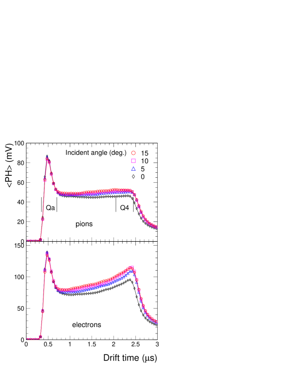
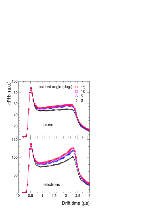
In Fig. 3 we present the dependence of the average pulse height, , on the drift time, for different incident angles , for pions and electrons. These average signals were recorded for the anode voltage of 1.55 kV. They are the sum of all eight pads and consequently are not influenced by the charge sharing between adjacent pads, which depends on the angle of incidence. The overlap of the long ion tails (TRF) results, in case of pions, in a slightly rising average pulse height as a function of the drift time, as seen in Fig. 3 for large angles. The peak at short drift times originates from the primary ionization (d/d) generated in the amplification region, where the signal from both sides of the anode wires overlaps in the same time interval. Due to the stronger field, the drift velocity in the amplification region is considerably larger than in the drift region. Consequently, the timing characteristics of the signal from the amplification region is determined mainly by the shaping time of the PASA. As the angle decreases towards normal incidence, the signal is progressively attenuated as a function of drift time, a clear indication of the effect of space charge. As this is a local effect, when spreading the primary electrons along the anode wire, the effect becomes less important, at least for our moderate values of the gain. Note that the amplitude of the signal in the amplification region is independent of the angle, since there are no previous avalanches that can screen it. Only a trivial normalization of the data for different angles is done to take into account the variation of the effective track length with the angle. We note that our measurements established for the first time [19, 2] the expected time evolution of the signal in this type of drift chambers. It is possible that earlier measurements [20, 21, 14], showing a decreasing value of the average signal in the drift region, suffered from space charge effects within a single track, due to the normal incidence used. For electrons, the contribution of transition radiation (TR), which is absorbed preferentially at the entrance of the drift chamber and is registered superposed on d/d, results in the strong rise of the average signal towards the end of the drift time. The d/d of electrons is in the regime of the Fermi plateau and consequently is on average about 40% larger than for pions at 3 GeV/c [22].
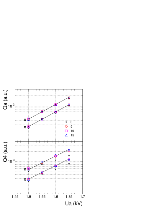
Marked in Fig. 3 by vertical lines are the limits used to calculate the average integrated charges in the amplification region, Qa, and in the last quarter of the drift region, Q4. These charges are plotted in Fig. 4 as a function of the anode voltage for all the incident angles, for pions and electrons. These dependences reflect the exponential gas gain increase as a function of the anode voltage, represented by the lines. In the presence of space charge the measured charges would flatten for higher anode voltages [15], in particular at normal incidence, when the charge is collected in a narrow spot on the anode wire. An exponential behavior is seen for Qa for all angles, demonstrating that no space charge effects due to rate occur for our voltage values. Taking into account our beam conditions (3000 particles in half a second, spread uniformly in a disk of 3 cm diameter) results in a rate of about 50 Hz per mm of anode wire. This is a very low local rate, compared to the value of 106 Hz/mm, estimated from the X-rays measurements of ref. [7] to be the onset of rate-induced space charge effects for a gas gain of about 4000. The fact that only Q4 shows a flatter dependence on anode voltage for the normal incidence can only be caused by the space charge produced by the avalanches of the earlier ionization electrons of the same track. Larger d/d and the contribution of TR makes the effect larger for electrons.
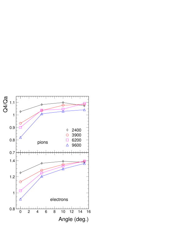
The ratio Q4/Qa is plotted in Fig. 5 as a function of the incident angle for four values of the gas gain for pions and electrons. For pions, due to track segment considerations, this ratio should be close to unity, but its absolute value is influenced by the integration windows (through the finite time bin size) and by the TRF. For electrons, due to the contribution of TR, the ratio has a larger value. In the absence of screening due to space charge, for both pions and electrons this ratio would be independent of the incident angle, but we observe a marked variation as a function of angle, in particular a sharp drop for small angles. A saturation is reached at large angles due to the locality of the screening. This behavior was observed before with an Ar-based mixture [5], albeit with a different magnitude, due probably to the much larger gas gain used in that study. More recently, similar results were obtained for a He-based mixture [8]. As expected from space charge considerations, we observe a stronger variation of the ratio for larger gains, in qualitative agreement with other observations [8].
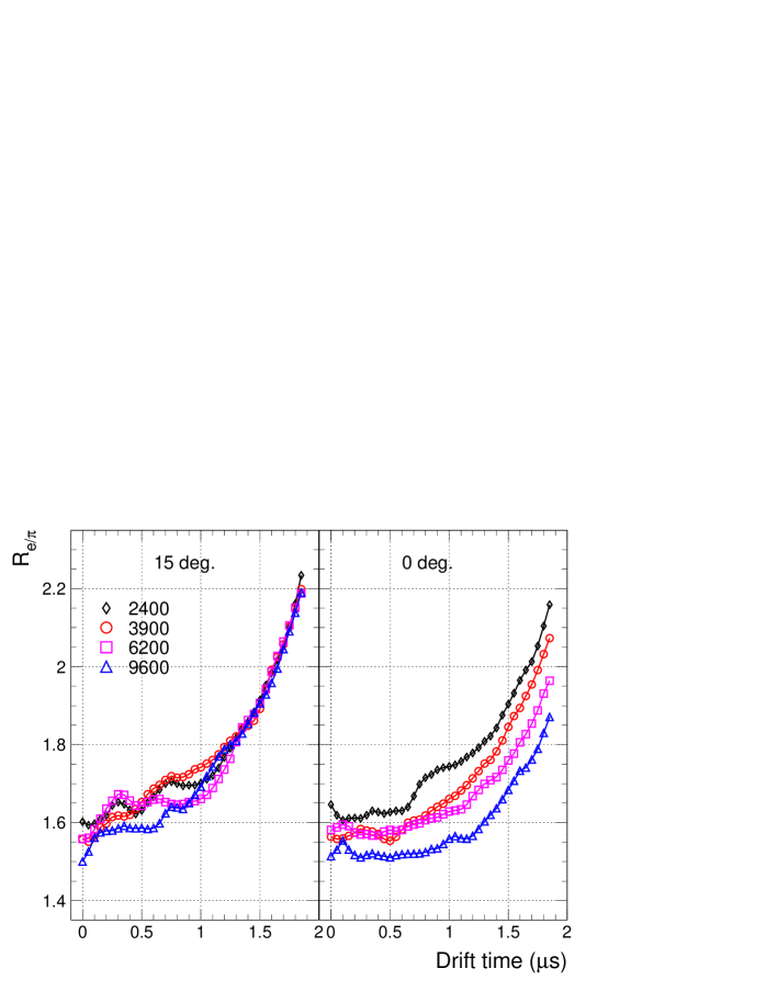
In Fig. 6 we present the ratio of the average signal of electrons to pions, , as a function of drift time, for two extreme cases of incidence, 15∘ and 0∘ and for four values of the gas gain. The time dependence of is due to the contribution of TR. This ratio is independent of the gas gain for the angle of 15∘, when space charge plays no role. Conversely, at normal incidence, when space charge is most important, a progressive reduction of is seen as a function of gas gain. The ratio is a direct measure of the electron/pion separation power of a TRD.
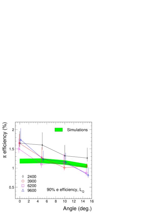
The observed stronger attenuation of the signal due to space charge for electrons compared to pions does affect the electron/pion identification performance of a TRD. For our case, we calculate the pion efficiency for 90% electron efficiency using a likelihood method [23] on the total energy deposited in a single chamber. Again, to improve statistics, each of the four layers has been treated as a separate detector and its total charge filled in a common histogram, for pions and electrons separately. We use these two charge distributions in a simulation program to calculate the likelihood (to be an electron) for a six layer detector, corresponding to the configuration of ALICE TRD. A 90% efficiency cut has been selected in the likelihood distribution of electrons and the pion contamination has been calculated. The results are presented in Fig. 7 as a function of incident angle for our four values of the gas gain. A pion rejection factor (inverse of the pion efficiency) of about 100 is achieved for finite angles of incidence, fulfilling the ALICE design goal [1]. One can see the expected degradation of the pion rejection power as the incident angle approaches normal incidence. Besides the space charge, two other contributions have to be recognized: i) the improvement of pion rejection for larger gains due to larger values of the signal-to-noise ratio (S/N); ii) the improvement of pion rejection as a function of angle arising from a thicker effective radiator and detector. To quantify this last effect, we calculate the angle dependence of the pion efficiency using simulated events. A parametrization for a regular radiator was tuned to reproduce the measured pion efficiencies at 15∘. Space charge effects are not included in the simulations, which are performed at a constant S/N. The results are represented by the dotted line and the shaded area in Fig. 7. Although the statistical errors of the measurements are rather large, an obvious degradation of the pion rejection is observed for normal incidence. For the upper values of our gas gain we measure at a pion rejection worse by a factor of 1.5 beyond the expected contribution due to the effective thicknesses. A similar degradation for normal incidence was observed, albeit with a much greater magnitude, in electron/pion identification using d/d measurements with prototypes for the PHENIX experiment and was also attributed to space charge [24].
Since our FADC measurements make available the time dependence of the avalanche charge for each individual track, it is conceivable that the space charge effects can be corrected using this information. We have implemented such a procedure, in which the measured amplitude of a given time bin is corrected by a factor which depends on the total charge registered prior to this time bin. The correction is done event-by-event, in an identical (”blind”) way for both pions and electrons and is tuned to restore the average ratio R⟨PH⟩ (see Fig. 10) to a flat dependence on the drift time. This correction is successful in restoring the ratio (see Fig. 6) for 0∘ incidence to the value measured at 15∘. However, the pion rejection factor is improved only marginally because the fluctuations of the charge distributions are amplified by the correction. For instance, the r.m.s. of the pion charge distribution is 77% before and 87% after correction (compared to 71% at 15∘ incidence).
The degradation of the electron/pion identification performance for tracks approaching normal incidence to the anode wires is an important argument for operating detectors at the lowest possible gas gain. Concerning the ALICE TRD, the optimal gas gain value is a compromise between the requirements on pion rejection and on position resolution, which is strongly improving as a function of S/N. We note that, due to the geometry of the ALICE TRD, normal incidence occurs rather seldom. The features presented above in case of electron/pion identification with TRD apply also to the identification of other particle species using energy loss in ionization detectors. Lighter gas mixtures show the effect of space charge as well [8, 25].
4 Comparison to simulations
For a quantitative understanding of the observations presented before we have performed a Monte Carlo simulation of the detector signal. The underlying physical picture has been described in [15] and will be briefly summarized in the following.
The electric field around the anode wire is assumed to correspond to an ideal cylindrical geometry and is given by the charge density on the wire:
| (1) |
with , where is the wire capacitance per unit length and the anode voltage. The ions produced in an avalanche form a cylinder of positive space-charge with radius and charge density surrounding the anode wire. The presence of the space-charge cylinder leads to a modification of the charge density on the wire. Inside the space-charge cylinder the electric field is
| (2) |
where is the modified charge density on the wire. Outside the space-charge cylinder the field is
| (3) |
The value of is determined by the potential difference between anode wire and cathode:
| (4) |
| (5) |
with anode wire radius and anode-cathode distance . The charge density on the wire is reduced by
| (6) |
where
| (7) |
The shielding factor decreases with increasing and thus depends on the drift time of the ion cloud because the ions are slowly drifting towards the surrounding cathodes. The drift time is determined by the ion mobility
| (8) |
assuming that the ion drift starts at the wire surface at .
The relative gain variation depends on the variation of the charge density via [15]:
| (9) |
with the Diethorn parameter V in xenon mixtures.
In the case of the TRD, the multiplication of a given drift electron is reduced by the shielding effect of the ion clouds produced by preceding electrons in the same event. As input to the simulation we use the spatial distribution of ionization electrons along the particle trajectory in the detector gas. The arrival time at the anode wire has been calculated using GARFIELD. The arrival point along the wire is determined by the incident angle of the simulated track and smeared by transverse diffusion.
The computation of the actual multiplication factor of an electron requires the consideration of the ion clouds with charge density built up by previous electrons () and their respective shielding factors . The ion drift time is equal to the difference of the arrival times of the electrons and . The ion charge density produced by electron with elementary charge is given by
| (10) |
where is the lateral extent of the avalanche along the wire and is the actual multiplication factor of electron which itself had been reduced by previous electrons.
Using Eq. (4) the modified charge density at the time of the arrival of electron can be calculated:
For the reduction of the charge density at the arrival time of electron we obtain:
| (11) |
which is identical to Eq. (6) for the case . Inserting this result into Eq. (9) yields the multiplication factor for electron .
It is important to note that the contribution of an electron in Eq. (4) and (11) is only considered if the lateral distance of the arrival points at the wire of electrons and is smaller than . In this way, the dependence of the space charge effect on the incident angle is introduced. It is also required that the ions have drifted at least 50 m away from the wire to ensure that the ions are outside the amplification region.
The number of primary electrons used in the simulations are the measured values. For our momentum of 3 GeV/c, we measure [22] an average energy deposit for pions of 5.5 keV/cm, which amounts for our gas mixture to 243 primary electrons per cm. 170 electrons from the amplification region arrive at the anode in a fraction of a s, while, from the drift region, 729 electrons arrive at a constant rate over the drift time of 1.8 s. For instance, after gas amplification this corresponds, for a gas gain of 3900, to a total charge of 106 fC and 455 fC, respectively. For electrons we use the time-dependent ratio measured at 15∘ incidence (left panel of Fig. 6), which is independent of the gas gain. All the other input values used in the calculations are summarized in Table 1.
| Parameter | Value |
|---|---|
| Anode voltage | 1550 V, 1600 V, 1650 V |
| Gas gain | 3900, 6200, 9600 |
| Anode wire radius | 10 m |
| Anode-cathode distance | 3.5 mm |
| Ion mobility | cm2/V/s |
| 30 V | |
| Wire capacity | F/cm |
| Avalanche spread | 50 m |
| Transverse diffusion coefficient | 330 m/ |

The calculated average relative gain values as a function of drift time are shown in Fig. 8 for pions and electrons at normal incidence, for three values of the gas gain. The sharp drop of the gas gain in the first 0.1 s is due to the effect of the large charge densities from the energy deposit in the amplification region. After this, the gain reduction due to space charge approximately levels off in case of pions as a result of an equilibrium between the incoming charge from the drift region at a roughly constant rate and the movement of the ions from previous avalanches away from the anode. The gain reduction for electrons is stronger than for pions and with a more pronounced time dependence. As already explained, this is due to the larger average signals for electrons, in particular with the contribution of TR at large drift times. For the largest value of the gas gain a reduction of the signal at the end of the drift time by about 30% is observed for pions and by about 40% for electrons.
For an exact description of the measured signals, the arrival time distribution of the primary electrons is folded by the single-electron TRF, which has been determined experimentally from the signal shape of 55Fe events (see Fig. 1). The resulting simulated signals are shown in Fig. 9 for tracks with different incident angles. A very good overall agreement with the measured signals is seen. As in case of the measurements, a clear reduction of the pulse height for tracks with small incident angle can be observed as a function of drift time.
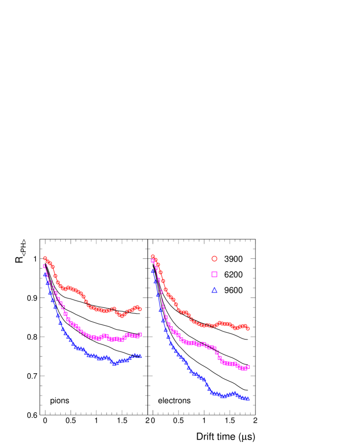
To quantify the signal reduction, we construct the ratio of the average signal at normal incidence to the average signal at the largest incidence, R⟨PH⟩. From the measured behaviour of charge ratios as a function of angle, seen in Fig. 5, one can conclude that the screening is negligible for our largest angle of incidence. Indeed, our simulations show that, for 15∘ incidence, the gain at the end of the drift is reduced by only 1.5%. As a consequence, R⟨PH⟩ is a quantitative measure of the screening at normal incidence. In Fig. 10 we present the dependence of this ratio on drift time for pions and electrons for three values of the gas gain. The time reference has been chosen to be the time of the maximum (corresponding to s in Figs. 3 and 9). The measurements are compared to calculations. The fine structure of the measured data is an artifact of signal fluctuations due to limited track statistics. Despite the simplifying assumptions involved, the calculations are in a reasonable agreement with the measurements, in the magnitude as well as in the shape.
5 Summary
We have reported measurements on space charge effects within a single track and the dependence of the pion rejection performance on the incident angle, carried out using prototype detectors for the ALICE TRD. Our measurements of average pulse height distributions in drift chambers operated with Xe,CO2(15%) provide quantitative results on the signal reduction within a given track due to space charge accumulation during the drift of the primary ionization. We have shown that the pion rejection performance of a TRD is impaired for tracks at normal incidence to the anode wire plane. Since in general normal incidence cannot be avoided in drift chambers, the only possibility to minimize the space charge effects is to chose the lowest possible gas gain allowed by a reasonable compromise on the desired position resolution of the detector. Our detailed simulations of the detector signals are in a remarkable agreement with the measurements, hence demonstrating that space charge is the explanation for the observed signal reduction within a signal track at normal incidence to the anode wires.
Acknowledgments
We acknowledge A. Radu and J. Hehner for the skills and dedication in building our detectors and N. Kurz for help on data acquisition. We would also like to acknowledge P. Szymanski for help in organizing the experiment and A. Przybyla and M. Wensveen for technical assistance during the measurements.
References
- [1] ALICE TRD Technical Design Report, CERN/LHCC 2001-021, October 2001; http://www-alice.gsi.de/trd/tdr.
- [2] A. Andronic et al., Nucl. Instr. Meth. Phys. Res. A 498 (2003) 143 [physics/0303059].
- [3] R.W. Hendricks, Rev. Sci. Instr. 40 (1969) 1216.
- [4] H. Sipilä and V. Vanha-Honko, Nucl. Instr. Meth. 153 (1978) 461.
- [5] A. Breskin, G. Charpak, F. Sauli, M. Atkinson, G. Schultz, Nucl. Instr. Meth. 124 (1975) 189.
- [6] F. Sauli, CERN Report 77-09 (1977).
- [7] R.A. Boie et al., Nucl. Instr. Meth. 201 (1982) 93.
- [8] K. Emi et al., Nucl. Instr. Meth. Phys. Res. A 379 (1996) 225.
- [9] S. Palestini et al., Nucl. Instr. Meth. Phys. Res. A 421 (1999) 75.
- [10] H. Sipilä, V. Vanha-Honko, J. Bergquist, Nucl. Instr. Meth. 176 (1980) 381.
- [11] E. Mathieson, Nucl. Instr. Meth. Phys. Res. A 249 (1986) 413.
- [12] G. Scherberger et al., Nucl. Instr. Meth. Phys. Res. A 424 (1999) 495.
- [13] M. Aleksa, C.W. Fabjan, W. Riegler, Nucl. Instr. Meth. Phys. Res. A 478 (2002) 135.
- [14] J.-F. Detoeuf et al., Nucl. Instr. Meth. Phys. Res. A 265 (1988) 157.
- [15] W. Blum and L. Rolandi, Particle Detection with Drift Chambers, Springer-Verlag, 1994.
- [16] J. Groh, E. Schenuit, H. Spitzer, Nucl. Instr. Meth. Phys. Res. A 283 (1989) 730.
- [17] H.G. Essel and N. Kurz, IEEE Trans. Nucl. Sci. vol. 47 (2000) 337.
- [18] CERN PS, http://psdoc.web.cern.ch/PSdoc/acc/pscomplex.html.
- [19] A. Andronic et al., IEEE Trans. Nucl. Sci. vol. 48 (2001) 1259 [nucl-ex/0102017].
- [20] Y. Watase et al., Nucl. Instr. Meth. Phys. Res. A 248 (1986) 379.
- [21] R.D. Appuhn, K. Heinloth, E. Lange, R. Oedingen and A. Schlösser, Nucl. Nucl. Instr. Meth. Phys. Res. A 263 (1988) 309.
- [22] A. Andronic et al., accepted for publication in Nucl. Instr. Meth. Phys. Res. A (2003) [physics/0310122].
- [23] A. Büngener, B. Koppitz, R. van Staa, P. Stähelin, M. Holder, Nucl. Instr. Meth. 214 (1983) 261.
- [24] B. Libby et al., Nucl. Instr. Meth. Phys. Res. A 367 (1995) 244.
- [25] M. Hauschild, Nucl. Instr. Meth. Phys. Res. A 379 (1996) 436.