Influence of the surface termination to the point imaging by a photonic crystal slab with negative refraction
Abstract
Point imaging by a photonic crystal slab due to the negative refraction is studied theoretically. By investigating the transfer function of the imaging system, the influence of the surface termination to the imaging quality is analyzed. It is shown that an appropriate surface termination is important for obtaining an image of good quality.
pacs:
78.20.Ci, 42.70.QsA photonic crystal Yablonovitch (1987); John (1987); Joannopoulos et al. (1995) is an artificial structure which has a periodic arrangement of dielectric or metallic materials. Photonic crystals have been extensively studied for their unique optical properties. For instance, they may provide a possibility of forbidding light propagation within a frequency band, i.e., a photonic bandgap. So far, most of the studies in the literature are focused on this optical bandgap property and its applications.
As another equally important property, unconventional ultra-strong dispersions, e.g., the superprism effect, exist in some photonic crystals in some frequency regions. Such an ultra-strong dispersion was firstly reported by Lin et al., and demonstrated experimentally in the millimeter-wave spectrum Lin et al. (1996). Kosaka et al. then demonstrated the superprism effect in a highly dispersive photonic microstructure (a complex “autocloned” photonic crystal) at optical wavelengths Kosaka et al. (1998). These unusual properties provide an exciting possibility for obtaining microphotonic and nanophotonic devices that can focus, disperse, switch, and steer light. For example, the superprism effect can be used in light collimating Kosaka et al. (1999) and wavelength multiplexing Wu et al. (2002). Recently, it is found that in some frequency regions some photonic crystals can also refract light as if they have a negative refractive index Qiu et al. (2003); Notomi (2000); Cubukcu et al. (2003). This has many potential applications such as self-focusing and imaging Luo et al. (2002); Parimi et al. (2003); Li and Lin (2003). Different from conventional lenses, in some photonic crystals evanescent waves could be amplified due to the existence of surface modes Luo et al. (2003), as well as in a left-handed material Pamakrishna et al. (2002). This is vital for subwavelength imaging.
In the present letter, we study point imaging by a two-dimensional photonic crystal slab due to the negative refraction, in particular, the influence of the surface termination of the photonic crystal slab to image quality.
The two-dimensional photonic crystal we considered here is a triangular lattice of air holes in a dielectric material , with a lattice constant and a hole radius . Only the transverse magnetic (TM) modes are considered here. For waves at a low frequency (or long wavelength), the material modulation of the periodic structure does not influence much the wave propagation. For waves at higher frequencies, propagation in the photonic crystal is complicated. However, Bloch-Floquet waves (eigen modes in the photonic crystal) travel through the photonic crystal with a definite propagation direction despite the presence of scattering Sakoda (2001). To visualize and analyze light propagation in a photonic crystal, an equal frequency surface (EFS) Notomi (2000) in k space of the photonic bands can be introduced, where gradient vectors give the group velocities of the photonic modes. For the photonic crystal considered here, the shape of the EFS corresponding to a frequency in the second band is almost circular Notomi (2000). One can then define an effective refractive index from the radius of the EFS with Snell’s law Qiu et al. (2003); Notomi (2000); Cubukcu et al. (2003) and use it to describe the light refraction in the photonic crystal. To assure all-angle negative refraction, here we choose the frequency , at which the effective refractive index of the photonic crystal is . It should be noted that the behavior in a photonic crystal with is quite different from that in a left-handed material(LHM)Shelby et al. (2001); Smith et al. (2000); Pendry (2000). For a LHM with , light can go through an air-LHM interface without reflection Pendry (2000). One may observe a quite different behavior at an interface between air and a photonic crystal even when the effective refractive index of the photonic crystal is . For example, the transmission from air into such a photonic crystal is nearly zero even at a normal incidence when the normal of the photonic crystal surface is along direction (the reason is that the incident plane wave has an even symmetry while the Bloch-Floquet wave in the photonic crystal has an odd symmetry).
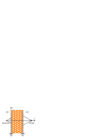
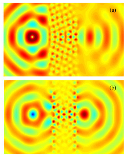
Consider an imaging system composed by a symmetric photonic crystal slab (with a thickness of seven rows of air holes), which is surrounded by air. The imaging system with coordinates is shown in Fig. 1, where is the surface termination of the photonic crystal slab at each interface. When , the distance between the left boundary of the photonic crystal slab and the left boundary of the first column of circles is . The normal of the slab interface is along the direction. Numerical simulations are performed using the finite-difference time-domain (FDTD) method Yee (1966) with a boundary treatment of perfectly matched layers Berenger (1994). A point source of continuous wave is placed at the left side of the photonic crystal slab. Figure 2(a-b) give the snapshots of the electric field for and , respectively. Focused images are observed on the right side of the photonic crystal slab for both positions of surface termination. The simulations clearly demonstrate the negative refraction in such a photonic crystal slab. However, in Fig. 2(a), the image is relatively blurred, which indicates that the reflection at the slab interface is probably quite high. The case of (corresponding to Fig. 2(b)) has a better image than the case of (Fig. 2(a)). The position of the surface termination influences quite much the reflection at the interface between air and the photonic crystal (and consequently the image quality). Note that it happens that the source and the image in Fig. 2 have a -difference in phase for both positions of surface termination. In general, an arbitrary phase shift may be achieved by e.g. choosing an appropriate thickness of the photonic crystal slab Luo et al. (2002); Li and Lin (2003).
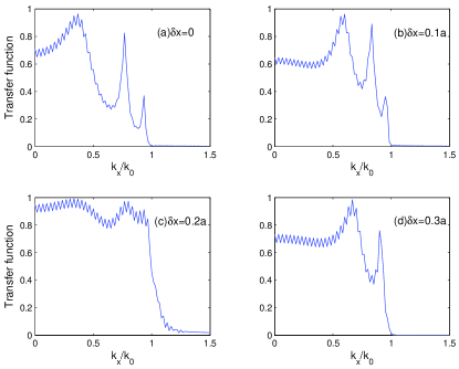
Since the photonic crystal slab is terminated with air at both sides, only one propagating mode exists at the right side of the photonic crystal slab for each incident plane wave component. Thus, we can apply the transfer function method to analyze the influence of the surface termination to the image quality (see e.g. Shen and He (2003)). Utilizing the discrete Fourier transform algorithm and the FDTD method, we can obtain the transfer function for such a photonic crystal slab. Figure 3(a-d) give the transfer functions of the imaging system with surface termination at , , , and , respectively. From Fig. 3 one sees that the transmission through the photonic crystal slab is strongly angular dependent, which is quite different from the case of a LHM () slab in air. This is mainly due to the angular-dependent coupling coefficient at the interface between air and the photonic crystal. Figure 3 also shows that the transmission depends on the surface termination of the photonic crystal slab. Compared with the results for other surface terminations, the transmission is relatively large when . From Fig. 3(b) one sees that the transfer function for is relatively flat at all propagating angles, which is essential for obtaining an image of good quality. From Fig. 3 one can also see that there exit some peaks in each transfer function. The peak positions vary for different surface terminations. This is probably due to the Fabry-Perot resonant effect since the effective width of the photonic crystal slab will decrease as the surface termination of the photonic crystal slab increases.
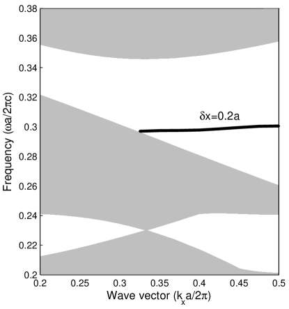
Surface modes are generally supported by appropriate crystal termination surfaces. The surface mode (solid line) of the photonic crystal along direction with surface termination is shown in Fig. 4. It is obvious that the surface mode approaches a flat line near the working frequency, . It has been shown in Luo et al. (2003) that the amplification of evanescent waves relies on resonant coupling mechanisms to surface photonic bound states. From Fig. 3 (c), it is also confirmed that, for (corresponding to the evanescent components of the source profile), the transmission of evanescent waves are much larger than those for other surface termination, with the help of the surface mode at the working frequency. It is important to obtain high imaging quality.
In summary, we have studied the point imaging for a slab of photonic crystal with negative refraction. The influences of the surface termination to the transmission and the imaging quality have been analyzed. The transfer function for the imaging system is obtained by combining the discrete Fourier transform algorithm with the FDTD method. Our simulation results have shown that the transmission is strongly angular dependent even when the effective refractive index of the photonic crystal is matched with the index of the air. It is also shown that the surface termination plays a key role in obtaining an image of relatively good quality.
This work was supported by the Swedish Foundation for Strategic Research (SSF) on Photonics, the Swedish Research Council (VR) under project 2003-5501, and the National Natural Science Foundation of China under key project (90101024) and project (60378037).
I References
References
- Yablonovitch (1987) E. Yablonovitch, Phys. Rev. Lett. 58, 2059 (1987).
- John (1987) S. John, Phys. Rev. Lett. 58, 2486 (1987).
- Joannopoulos et al. (1995) J. D. Joannopoulos, R. D. Meade, and J. Winn, Photonic Crystals: Modling the Flow of Light (Princeton Univ. Press, Princeton, NJ, 1995), 1st ed.
- Lin et al. (1996) S. Y. Lin, V. M. Hietala, L. Wang, and E. D. Jones, Opt. Lett. 21, 1771 (1996).
- Kosaka et al. (1998) H. Kosaka, T. Kawashima, A. Tomita, M. Notomi, T. Tamamura, T. Sato, and S. Kawakami, Phys. Rev. B 58, R10096 (1998).
- Kosaka et al. (1999) H. Kosaka, T. Kawashima, A. Tomita, M. Notomi, T. Tamamura, T. Sato, and S. Kawakami, Appl. Phys. Lett. 74, 1212 (1999).
- Wu et al. (2002) L. Wu, M. Mazilu, T. Karle, and T. F. Krauss, IEEE J. Quantum Electron. 38, 915 (2002).
- Qiu et al. (2003) M. Qiu, L. Thylen, M. Swillo, and B. Jaskorzynska, IEEE J. Sel. Top. Quantum Electron. 9, 106 (2003).
- Notomi (2000) M. Notomi, Phys. Rev. B 62, 10696 (2000).
- Cubukcu et al. (2003) E. Cubukcu, K. Aydin, E. Ozbay, S. Foteinopoulou, and S. C. M., Nature 423, 604 (2003).
- Luo et al. (2002) C. Luo, S. G. Johnson, J. D. Joannopoulos, and J. B. Pendry, Phys. Rev. B 65, 211104 (2002).
- Parimi et al. (2003) P. V. Parimi, W. T. Lu, P. Vodo, and S. Shridar, Nature 426, 404 (2003).
- Li and Lin (2003) Z. Y. Li and L. L. Lin, Phy. Rev. B 68, 245110 (2003).
- Luo et al. (2003) C. Luo, S. G. Johnson, J. D. Joannopoulos, and J. B. Pendry, Phys. Rev. B 68, 045115 (2003).
- Pamakrishna et al. (2002) S. A. Pamakrishna, J. B. Pendry, D. Schurig, D. R. Smith, and S. Schultz, J. Mod. Opt. 49, 1747 (2002).
- Sakoda (2001) K. Sakoda, Optical Properties of Photonic Crystals, Springer Series in Optical Sciences 80 (Springer Verlag, 2001), 1st ed.
- Shelby et al. (2001) R. A. Shelby, D. R. Smith, and S. Schultz, Science 292, 77 (2001).
- Smith et al. (2000) D. R. Smith, W. J. Padilla, D. C. Vier, S. C. Nemat-Nasser, and S. Schultz, Phys. Rev. Lett. 84, 4184 (2000).
- Pendry (2000) J. B. Pendry, Phys. Rev. Lett. 85, 3966 (2000).
- Yee (1966) K. S. Yee, IEEE Trans. Antennas Propag. 14, 302 (1966).
- Berenger (1994) J. P. Berenger, J. Comput. Physics 114, 185 (1994).
- Shen and He (2003) L. F. Shen and S. L. He, Phys. Lett. A 309, 298 (2003).
II Figure captions
Figure 1: (Color Online) Schematic diagram for an imaging system formed by a photonic crystal slab. The position of the surface termination is denoted by .
Figure 2: (Color Online) The snapshots of the electric field of a point source and its image formed by a photonic crystal slab with surface termination of (a); (b).
Figure 3: (Color Online) Transfer functions of of a photonic crystal slab (as an imaging system) for different surface terminations. .
Figure 4: The surface mode (solid line) of the photonic crystal for the termination factor . The shaded regions are the photonic band structures projected along the direction.