GePEToS : A Geant4 Monte Carlo simulation package for Positron Emission Tomography
Abstract
GePEToS is a simulation framework developed over the last few years for assessing the instrumental performance of future PET scanners. It is based on Geant4, written in Object-Oriented C++ and runs on Linux platforms. The validity of GePEToS has been tested on the well-known Siemens ECAT EXACT HR+ camera. The results of two application examples are presented : the design optimization of a liquid Xe PET camera dedicated to small animal imaging as well as the evaluation of the effect of a strong axial magnetic field on the image resolution of a Concorde P4 PET camera.
Index Terms:
Positron Emission Tomography, Monte Carlo Simulation, Geant 4.I Introduction
Over the last decade, the performance of Positron Emission Tomography (PET) scanners have considerably improved. For instance, commercial cameras dedicated to small animals now feature a space resolution below 2 mm along with a sensitivity better than 1% [1]. No matter how beneficial this performance gain has been to users, for instrument designers, it has somehow hardened the challenge of finding new solutions which would go beyond the present instrumental limits at an affordable cost. This is why the complete simulation of new TEP configurations under study has now become even more justified than in the past, and calls for the development of a dedicated simulation framework, sufficiently versatile to allow fast and very detailed approaches with the best-existing emulation of all the underlying physical processes. Since its first public release in 1998, the stability, the validity and hence the popularity of Geant4 [2]- the Object-Oriented particle tracking and transport simulation framework developed by the High Energy Physics community - have noticeably progressed. In our opinion, it has become the best toolkit from which any common and public TEP simulation framework should be developed. GePEToS : Geant4 Positron Emission Tomography Simulation, is a first attempt that we have made over the last few years to reach this goal .
II Adequacy for TEP scanners of Geant4-simulated physical processes
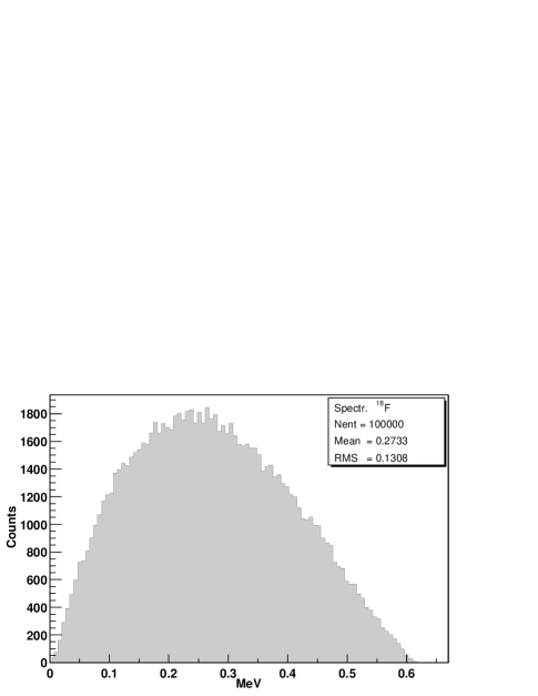
As we aimed at providing the possibility to fully simulate all the processes taking place during the short life of a positron and then in the transport and interaction of its two 511 keV annihilation photons, efforts were made to check the validity of Geant4 and if needed corrections or modifications were done. Hence, we have added as part of GePEToS the possibility to generate positrons according to their respective spectra for 18F, 15O, 11C (figure 1 for 18F). Table I shows the good agreement between our simulation and experimental data for the maximum and the most probable energies for each spectrum. After this step, the positrons are fully tracked down until they annihilate.
| : Most Probable Energy | ||||
|---|---|---|---|---|
| # Simulation | # Data [3] | # Simulation | # Data [3] | |
| 620 keV | 633 keV | 250 keV | 242 keV | |
| 950 keV | 959 keV | 375 keV | 385 keV | |
| 1750 keV | 1738 keV | 725 keV | 735 keV | |
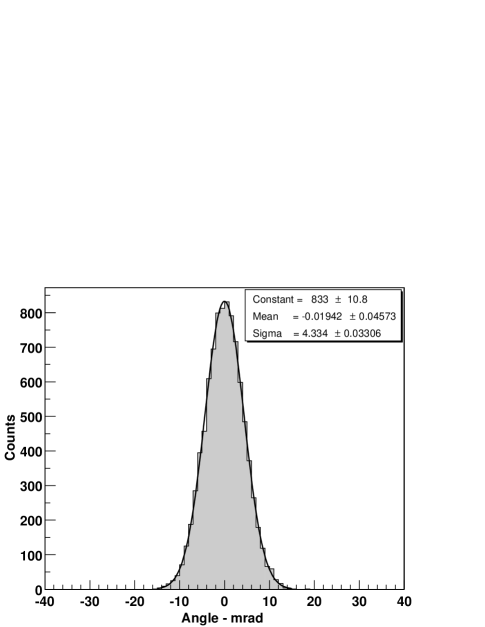
As Geant4 did not correctly reproduce the acolinearity of the two annihilation photons (( rad.) 10 mrad FWHM) which affects the image resolution, the native Geant4 algorithm has been modified to obtain a correct annihilation behavior in water where this phenomenon takes place in PET (figure 2). In water, the experimental measurement shows an energy shift between the two annihilation photons due to the orbital motion of the atomic electrons. This energy distribution is gaussian centered on zero with keV (FWHM) [4]. The relation between the energy shift and the acolinearity angle distribution is given by the formula :
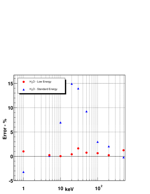
Finally, two Geant4 electromagnetic (EM) process packages have been tested : the Standard one and the LowEnergy one, dedicated to low EM physical processes. Comparisons between these two packages and the NIST experimental data [5] have been achieved. As an example, results on the total attenuation coefficient are presented hereafter on figure 3 : the low energy process package provides results in much better agreement with the experimental data. The difference is explained by the absence of Rayleigh scattering in the standard EM package. Indeed, the Low Energy package is now used in GePEToS even though it slightly increases the code CPU consumption.
III Framework description
GePEToS as Geant4, is fully written in Object-Oriented C++. It runs on Linux platforms (tested on RedHat 6.2). It uses a simple mechanism to define the geometry and the material composition of most of the PET cameras currently commercialized or under development (multi-ring and multi-crystal block devices). This is achieved by setting an ASCII configuration file in which users can select the desired isotope, the number of active rings, the dimensions and the segmentation of the crystal blocks, the nature of the crystal (NaI, LSO, BGO), the phantom type and the acquisition mode (2D or 3D). In addition, users have to provide the energy resolution measured or estimated at 511 keV which is then normally scaled according to the energy deposited in the crystals. For standard configurations, neither code modification nor recompilation are necessary. For every positron event and each of its two annihilation photons, GePEToS computes the deposited energy and an energy-weighted position in the transverse plane of the crystals which is then used to determine which crystal was hit. The depth of interaction (DOI) in crystals is also computed and stored if this readout mode is selected by users. Hit information is written in ROOT [6] files. Sinograms are separately prepared by using a ROOT application and finally processed by an IDL program [7] to reconstruct the tomographic images. More complex geometries, departing from the standard multi-ring crystal block model, can be handled with minor modifications of the code and by rebuilding the application.
IV Validation tests
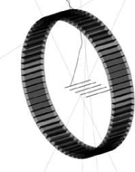
An exhaustive validation test of GePEToS has been achieved on one of the most common PET cameras used in medical examination centers : the Siemens ECAT EXACT HR+ PET scanner [8]. The ECAT EXACT HR+ PET scanner consists of 32 rings, featuring an internal diameter of 82.7 cm and spanning 15.2 cm in the axial field of view. It is made of blocks of BGO crystals. Each crystal has a transverse cross-section of 4 x 4.1 mm2 and is 30 mm long. This device, as modeled in GePEToS, is presented on figure 4, prepared for a 2D acquisition, for which the lead septa have been slid in front of the crystal rings. Also shown on the picture is one of the typical water phantoms (=20 cm, L=20 cm) that can be used in GePEToS to assess the performance of the cameras. Figure 7 also shows the HR+ scanner but in configuration of 3D acquisition mode, with the septa retracted.
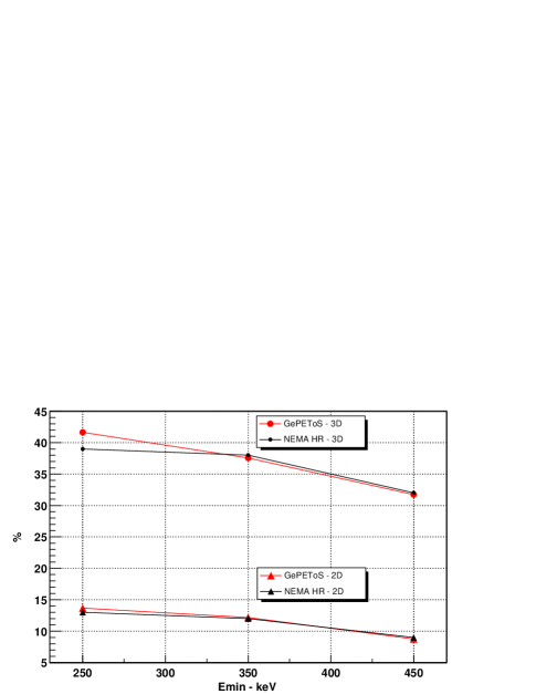
All comparisons of the simulated performance against the available experimental data [9] do show an excellent agreement. To illustrate this statement, figure 7 shows the results for the fraction of scattered coincidences as measured in the NEMA [10] experimental protocol in 2D and 3D acquisition modes with 18F. For the scatter fraction evaluation, the phantom which is defined in the NEMA protocol is a water cylinder (=20 cm, L=20 cm) with three axial 18F-loaded capillaries placed at the center, at 4 cm and 8 cm in the transaxial plane of the cylinder. The evaluation of total scatter fraction is given by this expression :
Here, , and are respectively the scatter fraction at the center, 4 cm and 8 cm in the phantom. The value of the transaxial Field Of View (FOV) is taken as 25 cm. The scatter fraction is defined for coincidences included in the energy window.
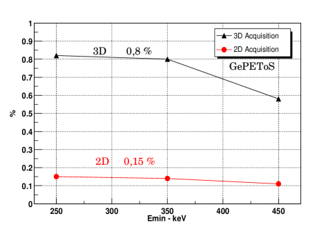
Figure 7 presents the simulation results for the sensitivity evaluation. The NEMA protocol for this calculation assumes a water cylinder filled with 18F for the phantom. The sensitivity value is determined by this equation :
For low energy cut values (250 keV and 350 keV), the sensitivity is 0.8 % and 0.15 % for 3D and 2D acquisition mode respectively. These simulation results can be compared to experimental values [8] which produce 0.8 % in 3D mode and 0.15 % for a 2D acquisition.
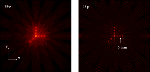
Also presented on figure 8 is the transaxial image resolution determined with five axial 18F-loaded capillaries (figure 7) which again shows a good agreement between the simulated and the experimental data. The results are produced by the FWHM gaussian fit on the pixel distribution of the reconstruted image. All quantitative results are reported in the table II.
V Application examples
In this section, we briefly describe two application examples of GePEToS which show that this simulation framework although in an infant stage, can be used to investigate a wide variety of PET problems.

| Transaxial Image Resolution (FWHM) | ||
|---|---|---|
| # GePEToS | # Data | |
| r = 0 cm | 4,2 mm | 4,4 mm 1 |
| r = 5 cm | 5,5 mm | 5,2 mm 2 |
| r = 10 cm | 5,6 mm | 6,4 mm 2 |
| r = 15 cm | 6,6 mm | 7,00 mm 2 |
| r = 20 cm | 7,9 mm | 8,0 mm 1 / 8,3 mm 2 |
V-A A liquid xenon PET camera
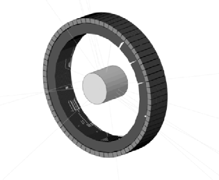
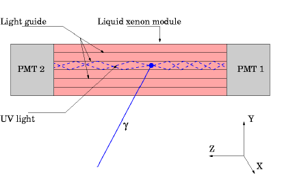
For several years, liquid xenon has been considered by two groups to build PET cameras [11] [12]. We have used GePEToS to optimize the design of a small animal PET camera which would exclusively use the scintillation light of LXe. The active part of the camera is a ring featuring an internal diameter of 10 cm and a radial extension of approximately 25 mm. It is filled with liquid xenon and placed in a cryostat composed of thin aluminum walls (especially around the imaging port). 16 identical modules of the type shown on figure 9, are immersed in this ring. Each module presents a 2 x 2 cm2 cross-section in the transaxial plane of the camera. The axial field of view spans 5 cm. A module is optically subdivided by 100 2 x 2 mm2 MgF2-coated aluminum UV light guides. The UV light is collected on both sides of a module by two position sensitive photo-tubes. The (x,y) positions measured by the photo-tubes determine which light guides have been fired : hence we measure the transaxial Depth Of Interaction (DOI) of the photons [13]. For each module, the axial coordinate is provided by the following ratio of the photo-tube signals :
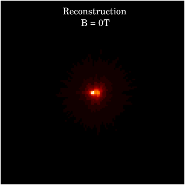
The performance of this device has been fully evaluated using GePEToS plus a dedicated light collection program written in C++. It assumes a quantum efficiency of the photo-tubes of 15% and a UV reflection coefficient of 90% for the light guides. The simulated 18F sensitivity of this device evaluated on a water cylinder of 4 cm in diameter and 4 cm in length is 0.6% for an energy threshold of 250 keV. Its image resolution after filtering is 1.6 mm (FWHM) throughout the view field, thanks to the DOI capability of the device. Figure 10 shows the reconstructed image of point-like 18F sources placed in the z=0 transaxial plane of a 4 cm diameter water cylinder. After filtering, these point-like sources are clearly resolved. Table III shows the image resolution at different points in the Field Of View (FOV) for the 18F, 11C and 15O : we see that the DOI measurements provide a good resolution uniformity in the FOV.
| 18F | 11C | 15O | |
|---|---|---|---|
| r=0 mm | 1,6 mm | 2,0 mm | 3,1 mm |
| r=5 mm | 1,9 mm | 2,6 mm | 4,0 mm |
| r=10 mm | 1,8 mm | 2,3 mm | 3,7 mm |
| r=15 mm | 1,6 mm | 2,3 mm | 3,3 mm |
V-B Magnetic field and image resolution
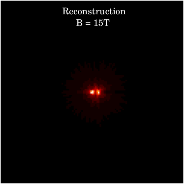
As Geant4 presents the capability to transport and track charged particles in strong magnetic fields, we used GePEToS to evaluate the potential image resolution gain of a P4 Concorde PET camera [1] which would be operated in the strong axial field of a MRI scanner. We found no improvement for 18F and a marginal gain for 11C. However for 15O and providing the device is operated in a 15 T solenoidal field, figures 11 and 12 show that the magnetic field allows to resolve two point-like sources separated by 4 mm. The physical explanation of this effect is very comparable to what happens in a TPC (Time Projection Chamber) operated in a magnetic field. The axial magnetic field blocks the transaxial diffusion of electrons and confines them within a spiral around their creation points. Our results are in good agreement with what was found in previous studies [14, 15]. 15 T MRI scanners are now becoming available for small animals, but the operation of photo-sensors in such a strong magnetic field remains a very difficult challenge for the future.
VI Conclusion and perspectives
We have established the basis of a PET simulation package (GePEToS) based on Geant4 as a transport and tracking engine. GePEToS has been validated against the available data of a Siemens ECAT EXACT HR+ PET scanner. We used GePEToS to guide our development effort toward a LXe PET camera dedicated to the small animal imaging. The sources of GePEToS can be freely downloaded from this site [16].
Acknowledgments
This work was made possible thanks to the financial grants allocated by the Rhône-Alpes region through its ”Emergence” science program and by CNRS/INSERM via its IPA program dedicated to the small animal imaging. We are also indebted to Jean-François Le Bas and Daniel Fagret of the Medical department of the Joseph Fourier University of Grenoble for the support and motivation they brought to this project.
References
- [1] A.F. Chatziioannou et al., ”Performance evaluation of microPET : a high-resolution oxyorthosilicate PET scanner for animal imaging,” Journal of Nuclear Medicine, vol. 40, p. 1164, 1999.
- [2] Geant4 web page : http://wwwinfo.cern.ch/asd/geant4/geant4.html
- [3] E. Browne, R.B. Firestone, ”Table of Radioactive Isotopes.” Virginia S. Shirley Editor.
- [4] P. Colombino et al., ”Study of positrunium in water and ice from 22 to -144 by annihilation quanta measurements,” Nuovo Cimento, vol. XXXVIII, no 2, 1965.
- [5] NIST web page : http://physics.nist.gov/PhysRefData/
- [6] ROOT web page : http://root.cern.ch
- [7] IDL web page : http://www.rsinc.com/idl/index.asp
- [8] G. Brix et al., ”Performance Evaluation of a whole-body PET scanner using the NEMA protocol,” Journal of Nuclear Medicine, vol. 38, p. , 1997.
- [9] Private communication of Service Hospitalier Frederic Joliot - CEA - DSV - Orsay France.
- [10] National Electrical Manufacturers Association.NEMA Standards Publication NU 2-1994: Performance Measurements of Positron Emission Tomographs. Washington, DC: National Electric Manufacturers Association; 1994.
- [11] V. Chepel et al., ”Performance study of liquid xenon detector for PET,” Nucl. Instr. and Meth., A392, p.427, 1997.
- [12] J. Collot, S. Jan and E. Tournefier, ”A liquid xenon PET camera for neuro-science,” IX Int. Conf. On Calorimetry in Part. Phys. - Annecy 2000, Frascati Physics Series, vol. XXI, 305, 2001.
- [13] S. Jan, ph.D. Thesis, University of Grenoble (UJF, Grenoble, France), september 2002.
- [14] R. Raylnan et al., ”Combined MRI-PET Scanner: A Monte Carlo Evaluation of the Improvements in PET Resolution Due to the Effects of a Static Homogeneous Magnetic Field,” IEEE Transactions on Nuclear Science, vol. 43, p.2406-2412, 1996.
- [15] B. Hammer et al., ”Measurement of Positron Range in Matter in Strong Magnetic Field,” IEEE Transactions on Nuclear Science, vol. 42, p.1371-1376, 1995.
- [16] GePEToS web page : http://isnwww.in2p3.fr/tep/gepetos.html