2
Distortion-free tight confinement and step-like decay of fs pulses in free space
University of Pecs, Ifjusag u. 6, H-7624 Pecs, Hungary)
Abstract
A method of formation of the tightly confined distortion-free fs pulses with the
step-like decreasing of intensity under the finite-length
propagation in free space is described. Such pulses are formed by
the Fresnel source of a high refraction-index waveguide. The
source reproduces in free space a propagation-invariant
(distortion-free) pulse confined by the waveguide. Converse to the
case of material waveguides, when the pulse goes out from the
Fresnel (virtual) waveguide its shape is not changed, but the
intensity immediately drops down to the near-zero level.
OCIS numbers: 320.0320, 320.2250, 320.5540, 320.5550.
Tight transverse confinement of a light wave in free space together with fast decreasing of its intensity after the finite-length propagation are required in many fields of optics, such as non-destroying light-matter interaction, control of light penetration-depth and surface processing. The effect is usually achieved by strong focusing a light beam by short-curvature-radius lenses or spherical mirrors. In the case of fs pulses, the control of the transverse and longitudinal intensity distributions is a particularly difficult problem, because the ultrashort pulses are distorted in the space and time domains by such optical elements (see, for example Refs. [1, 2, 3, 4, 5, 6]). Recently, it was shown that the tightly confined propagation-invariant (distortion-free) continuous waves with the fast decreasing of the intensity after the finite-length propagation in free space could be formed by the Fresnel source of a high refractive-index hollow waveguide having total-reflection walls [7, 8]. If such an effect exists for the ultrashort pulses, this could be very important for the fs optics and applications. In the present article, the formation of tightly confined distortion-free fs pulses with the step-like decreasing of intensity under finite-length propagation in free space is described.
Let us describe the Fresnel source that reproduces in free space a propagation-invariant (distortion-free) pulse tightly confined by a high refractive-index hollow waveguide with total-reflection walls. The plane-parallel guide having the length and width is considered. A propagation-invariant time-harmonic wave is supported in the free-space by the constructive interference of multiple beams launching from the Fresnel zones of the virtual source of the guide [9]:
| (1) |
with
| (2) |
where is the number of zones (beams) of the Fresnel source that contribute the energy into the field ; and ; is the wave frequency; is the distance between points and ; , where is the field at the guide entrance . The value is determined by the transverse dimension of the beam at the guide exit . By analogy with the Fresnel lens, the virtual source of the waveguide is called the Fresnel waveguide [8]. The source reproduces in free space a diffraction-free beam [10, 11, 12, 13, 14] confined by the waveguide. In the case of an ultrashort pulse guided by the waveguide, the field of the pulse at the guide entrance is represented in the form of a Fourier integral . Using the Fresnel-waveguide representation for the Fourier components and substituting the result into the Fourier integral we get the propagation-invariant pulse in free space [9]. The pulse is supported in free space by the constructive interference of the ultrashort-pulses launching from the Fresnel source of the waveguide.
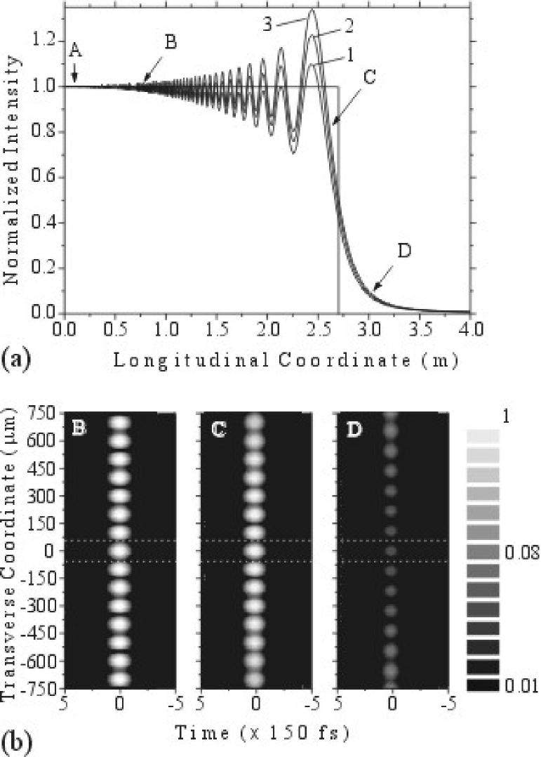
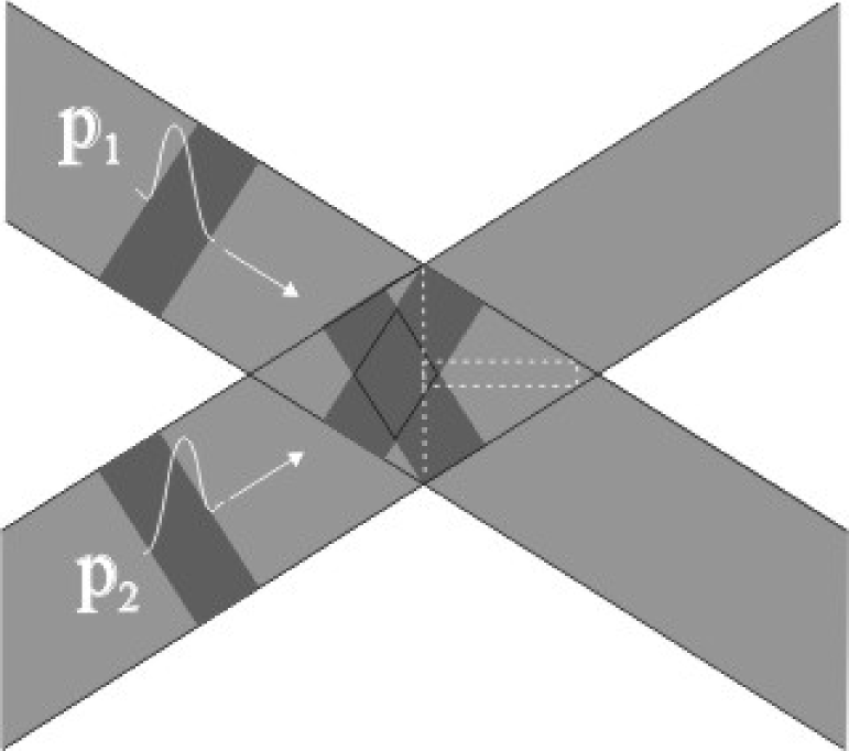
The Fresnel source reproduces in free space a distortion-free (propagation-invariant) pulse confined by the waveguide. Converse to the case of material waveguides [15, 16], when the pulse goes out from the Fresnel (virtual) waveguide its shape is not changed, but the intensity immediately drops down to the near-zero level. The effect, which looks like the instant decay or annihilation of a tightly confined pulse, is illustrated by the numerical examples in Figs. 1(a) and 1(b). Figure 1(a) shows the intensity distribution on the axis of the virtual waveguide computed for the pulse having the two different durations : 100 and 150 fs. The intensity distribution of the continuous wave is shown in the figure for the comparison. Figure 1(b) demonstrates the intensity distributions of the pulse (=150 fs) at the points B, C and D. We notice that the pulse propagates in the region of the virtual waveguide as the superposition of many pulses that diffract in the off-axis direction and interfere with each other. Analysis of the intensity distributions indicates existence of the two main stages of the evolution of the pulse under the free-space propagation: the propagation-invariant AC and collapse CD stages. In the region AC , the intensity distribution of the pulse is practically unchanged that demonstrates the propagation-invariant properties of the pulse. The pulse amplitude is constant in the region AB and shows some oscillations in the part BC of the region AC. The amplitude of these oscillations, which increases with increasing the pulse duration, reaches maximum value before the pulse decay. In the collapse region CD , the number of pulses is not sufficient for supporting of the propagation-invariant field distribution. In this region, the pulse shape is not changed, but the intensity immediately drops down to the near-zero level. The pulse decay is caused by the destructive interference between the pulses launched from the finite-width Fresnel source of the finite-length waveguide. The distance strongly correlates with the width of the Fresnel source. This presents a method of formation of the tightly confined distortion-free fs pulses with the step-like decreasing of intensity under the finite-length propagation in free space. The propagation length AC could be controlled by variation of the width of the Fresnel source. The above-described theoretical principle of the Fresnel source can be realized experimentally by using the fs-pulses. In the simplest case, the source can be formed by the interference of only two fs-pulses propagating in the off-axis direction, as shown in Fig. 2. Notice, that the two-pulse technique is similar to the method of formation of the dynamical gratings (see, for example Refs. [17, 18]).
In conclusion, a method of formation of the tightly confined distortion-free fs pulses with the step-like decreasing of intensity under the finite-length propagation in free space was described. The pulses are formed by the Fresnel source of a high refraction-index waveguide. The length of the distortion-free propagation and the time of the pulse decay are controlled by variation of the width of the Fresnel-waveguide source. It should be noted that the method can be extended to the guiding of fs pulses in free-space by the 3-dimensional virtual waveguides. In this case, one could use the Fresnel sources of 3-dimensional high-refraction-index waveguides [19].
This study was supported by the Fifth Framework of the European Commission (Financial support from the EC for shared-cost RTD actions: research and technological development projects, demonstration projects and combined projects. Contract NG6RD-CT-2001-00602). The authors thank the Computing Services Center, Faculty of Science, University of Pecs, for providing computational resources.
References
- [1] M. Kempe, U. Stamm, B. Wilhelmi, Opt. Commun. 59, 119 (1986).
- [2] Z. Bor, Opt. Lett. 14, 119 (1989).
- [3] S. Jackel, R. Burris, J. Grun, A. Ting, C. Manaka, K. Evans, J. Kosakowskii, Opt. Lett. 20, 1086 (1995).
- [4] M. Bertolotti, A. Ferrari, L. Sereda, J. Opt. Soc. Am. B 12, 1519 (1995).
- [5] M. Nisoli, S. De Silvestri, O. Svelto, R. Szipocs, K. Ferencz, Ch. Spielmann, S. Sartania, Opt. Lett. 22, 522 (1997).
- [6] M.E. Ferman, Opt. Letts. 23, 52 (1998).
- [7] S.V. Kukhlevsky, G. Nyitray, Opt. Commun. 218, 213 (2003).
- [8] J. Canning, E. Buckley, K. Lytikainen, Opt. Lett. 28, 230 (2003).
- [9] S.V. Kukhlevsky, G. Nyitray, V.L. Kantsyrev, Phys. Rev. E 64, 026603 (2001).
- [10] J.N. Brittingham, Appl. Phys. 54, 1179 (1983).
- [11] R.W. Ziolkowski, J. Math. Phys. 26, 861 (1985).
- [12] J. Durnin, et al, Phys. Rev. Lett. 58, 1499 (1987).
- [13] F. Gori, et al, Opt. Commun. 64, 491 (1987).
- [14] J. Y. Lu, J. G. Greenleaf, IEEE Trans. Ultrason. Ferroelec. Freq. Contr. 39, 19 (1992).
- [15] D. Marcuse, Theory of Dielectric Optical Waveguides (Academic Publishers, New York, 1974).
- [16] K. Okamoto, Fundamentals of Optical Waveguides (Academic Press, New York, 2000).
- [17] A. A. Maznev, T. F. Crimmins, K. A. Nelson Opt. Lett. 23, 1378 (1998).
- [18] G. D. Goodno, G. Dadusc, R. J. Miller J. Opt. Soc. Am. B 15, 1791 (1998).
- [19] S.V. Kukhlevsky, G. Nyitray, J. Mod. Opt. 50, 2043 (2003).
List of Figure Captions
Fig. 1. (a) The step-like evolution of the normalized intensity of the Gaussian-shaped ultrashort light pulse on the virtual-waveguide axis under the free-space propagation computed for the two different pulse durations : (1) - 100 fs and (2) - 150 fs. The intensity distribution of the continuous wave (3) and the step-like function (step(z)) are shown for the comparison. (b) The normalized intensity distributions of the propagation invariant (distortion-free) pulse ( = 150 fs) at the points B, C and D. The white dashed line indicates the region of the virtual waveguide. The guided pulse is supported in the free space by the diffraction and interference of pulses of the Fresnel-waveguide source. The intensity distributions were calculated using the following parameters: = 500 nm, [0.05 m, 4.05 m], [-750 m, 750 m], [-750 fs, 750 fs] and , where is the he central wavelength of the pulse (wave-packet).
Fig. 2. The schematic diagram of the Fresnel-wavegiude source formed by the interference of the two fs-pulses ( and ) propagating in the off-axis direction. The box indicated by the white dashed line shows the region of the virtual waveguide.