Development of Shashlyk Calorimeter for KOPIO
Abstract
A Shashlyk calorimeter prototype for the KOPIO experiment has been constructed and experimentally tested. The energy resolution of about for positrons was obtained. Based on this results as well as on the results of special measurements, a Monte-Carlo model of the Shashlyk module response was developed. This model, including the effects of shower evolution, light collection in scintillator plates, light attenuation in fibers, quantum efficiency of the photodetector, thresholds and noises in the readout system is consistent with experimental results. Possible improvment of the Shashlyk energy resolution up to , the level required by KOPIO experiment, are discussed.
keywords:
Shashlyk calorimeter , Monte-Carlo simulationPACS:
29.40.Vj , 07.05.Tp, , , , , and
1 Introduction.
The KOPIO experiment [1] at the Brookhaven National Laboratory (BNL) Alternating Gradient Sinchrotron (AGS) is designed to measure the decay rate for , a “gold plated” CP-violating process [2]. This experiment will provide the cleanest determination of the fundamental parameter that quantifies the phenomenon of CP violation in the context of the Standard Model. A measured decay rate very different from the precise expectation of the Standard Model, or one in conflict with CP violation results from the B sector, would be evidence for a new physics process.
A Photon Calorimeter which will occupy an area is one of the keystone elements of the KOPIO detector. Studies of Detector optimization led to the following requirements for photon detection, in the energy range of :
-
•
Energy resolution
-
•
Time resolution about
-
•
Calorimeter granularity
Shashlyk based calorimeter meets the specified requirements in an economical way. Such a calorimeter is composed of Shashlyk modules, which are lead-scintillator sandwiches read out by means of Wave Length Shifting (WLS) fibers passing through the holes in scintillator and lead.
The first Shashlyk calorimeter was designed and manufactured at Institute for Nuclear Research (Moscow) [3] in 1991 for the experiment 865 [4] (Search for the Lepton Number Violating Decay ) at the BNL AGS. During the five-year high intensity run of the experiment, the Shashlyk calorimeter was a very stable and reliable detector. Its features, together with its low cost and well understood method of construction, make this type of calorimeter a good candidate for other experimental projects. Similar calorimeters were built later for PHENIX experiment at RHIC (BNL) [5] and for HERA-B experiment at DESY [6]. A Shashlyk calorimeters was also studied as a candidate for the CMS experiment at LHC (CERN) [7], and one is now under construction for LHCb experiment [8].
The E865 and other constructed calorimeters were designed to have an energy resolution about . Significant improvements in calorimeter module construction can be made it possible to achieve the resolution required by experiment KOPIO.
The purpose of this paper is to study the ways of such an upgrade. Based on experience with the E865 module, a new prototype module has been designed, constructed and tested. As will be shown below this module provides an energy resolution about . While this improved resolution is not sufficient to meet the requirements of KOPIO, experimental studies of this module provide a reference point for tuning Monte-Carlo simulations. From such simulations, recommendations for constructing a Shashlyk calorimeter for KOPIO are made.
2 Design of KOPIO prototype module.
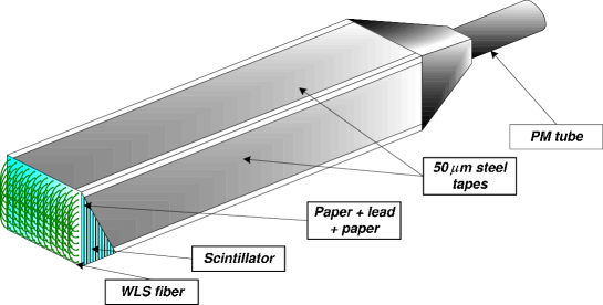
The design of a prototype module for KOPIO is shown in Fig. 1. Eighteen such modules had been produced at TECHNOPLAST (Vladimir, Russia).
2.1 Mechanical construction of module
The module is a sandwich of alternating perforated stamped lead and injection molded polystyrene-based scintillator plates. The transverse size of module is ; the thicknesses of plates are for lead and for scintillator. Each plate has 144 holes equidistantly arranged as matrix, with the spacing between the holes being . The diameters of the holes are 1.5 mm in the lead plates, while the holes in the scintillator have a conical shape with diameter ranging from 1.4 to 1.5 mm. 72 WLS fibers are inserted into these holes. Each fiber is looped at the front of the module, so that both ends of a fiber are viewed by the photo-multiplier tube (PMT). Less than of light is lost while passing the loop, which radius is about . The fiber ends are collected in one bunch, cut and polished, and connected to a PMT. To improve the light collection perforated white reflecting paper (TYVEK) is interleaved between lead and scintillator plates, and edges of scintillator plates are aluminized. The complete stack of all plates is held in compression by the four m stainless steel side strips that are pretensioned and welded to both front and back special endcaps.
Parameters of module are summarized in Table 1.
| Transverse size | |
|---|---|
| Number of the layers | 240 |
| Polystyrene scintillator thickness | |
| Lead absorber thickness | |
| Reflective paper (TYVEK) thickness | |
| Number of holes per layer | |
| Holes spacing | |
| Holes diameter in Scintillator/Lead | |
| WLS fibers per module | |
| Diameter of WLS fiber | , ( |
| Diameter of fiber bundle | , () |
| Effective radiation length | |
| Effective Molière radius | |
| Effective density | |
| Active length | () |
| Total length (without photodetector) | |
| Total weight |
2.2 WLS fibers and PM tubes
We have used three different types of fibers (KURARAY, diameter Y11(200)M-DC, and BICRON, diameter BCF-99-29A-SC and diameter BCF-92-SC) and different types of PMT’s (Russian FEU85 and FEU115, and 9903B of Electron Tubes Ltd (9903B)) for the tests.
The properties of WLS fibers used in our measurements are summarized in Table 2. These data were taken from manufacturer’s Catalogs. Experimental measurements [9] of the absorption spectra of WLS fibers in comparison with emission spectra of the scintillators are shown in Fig. 2.
| WLS fiber | BCF-92 | BCF-99-29A | Y11(200)M-DC |
|---|---|---|---|
| Manufacturer | BICRON | BICRON | KURARAY |
| WLS fluor | G2, | G2, | K27, |
| Emission peak, nm | 492 | 492 | 476 |
| Absorption peak, nm | 410 | 410 | 430 |
| Decay time, ns | 2.7 | 2.7 | 7 |
| Core material, | PS | PS | PS |
| refractive index | |||
| Inner cladding, | PMMA | PMMA | PMMA |
| refractive index | |||
| Outer cladding, | — | — | FP |
| refractive index | |||
| Trapping efficiency, % | 3.1 | 3.1 | 5.4 |
| Attenuation length, m | |||
| (for long fiber) | |||
| Fiber diameter, mm | 1.2 | 1.0 | 1.0 |

FEU85 is an eleven stages green-extended one inch PM tube with a good quantum efficiency for green light (Q.E. 15-20 %). The maximum anode current of this PMT is limited to mA per pulse, therefore it was used with a fast preamplifier with programmable gain K = .
FEU115 is an inexpensive high gain eleven stages PMT with an S20 photo-cathode response and with typical Q.E. for green light.
9903B is a ten stages green-extended tube with Rubidium bialkali (RbCs) photo-cathode and BeCu dynodes for lower gain , but with extended linearity (better than 1% up to 50 mA ) and a high short and long term gain stability. 9903B has a typical Q.E. for .
2.3 Light collection
Electrons and positrons from an electromagnetic shower produce ultraviolet and blue light in the scintillator plates which is absorbed and reemitted as green light in the WLS fiber. About of the green light is captured and transmitted by the fiber.
Due to the Shashlyk design, only light satisfying the criteria of a total internal reflection within the scintillator plate is captured by fibers. Since scintillator plates are thin compared to the average distance of light to the fibers, many reflections from the surface of scintillator occur. Thus, high reflection efficiency is very important for good performance. An internal reflection efficiency about is achievable for realistic surfaces. It should also be noted that modern technologies allow comparable diffusion reflection efficiencies to be realized by special chemical treatment of the surfaces [11].
Light collection uniformity in the direction transverse to the length of the module is also important in achieving good energy resolution. This requires good reflectivity at the edges of the scintillator plates since the total internal reflection at these surfaces is not necessary condition for the possibility of light penetrating to fiber. Thus the scintillator edges were aluminized to increase light reflection.
3 Experimental study of prototype module
The characteristics of the modules were studied on B2 test beam at AGS with positrons and pions. Measurements were done during the Spring and Fall test runs 1998. The prototype of calorimeter ( modules) was mounted on a platform which could be moved horizontally and vertically with respect to the beam line. Upstream of the calorimeter, a trigger counter telescope was installed which consisted of three beam defining scintillators (S1 - S3) and a veto lead-scintillator counter with a diameter hole through which the beam passed. A Cerenkov counter was used for identification of positrons.
The signals from PM tubes were read out using an wide gate with a LeCroy 1885 FASTBUS ADC providing 12 bits of dynamic range. A separate channel, including a PM tube without a Shashlyk module and located inside the detector box, was used to check for channel to channel coherent noise correlations. It was often found that the coherent noise was very high. A possible explanation of this effect is that there was no “clean ground” in the test beam area. The data from the runs with increased coherent noise were skipped in the off-line analysis.
Three types of triggers were used during the beam tests for monitoring and data taking : a random trigger to monitor pedestal behavior and to check noise correlations, and two beam triggers (with and without the veto counter) for measurements.
Each module was individually calibrated using either the minimum ionization peak from high momentum pions, or the deposited energy peak from positrons. In each calibration measurement about 5000 particles were passed through the central region of each module at normal incidence. Using these data, the calibration coefficients were estimated with precision better than .
The energy resolution was determined only for positrons passing through the area in the center calorimeter as defined by S3 scintillator.
The momentum spread of the beam significantly contributed to the apparent energy resolution in the modules at all measured energies. For beam momentums above , the spread was about . However, according to a GEANT [10] calculation, positrons passing through matter (15 m of Air and 3.5 cm of scintillation counters) lose about of their energy with fluctuations of about . This energy loss required significant corrections to the results of the measurements.
The intensity of beam was chosen sufficiently low to reduce pile-up and rate effects during the spill, but due to the large beam size this requirement was only partially met. The beam particle rates for a nonet of modules were ()K per spill. Small corrections for pile-up and rate effects were taken into account in data analysis.
The electronic noise term for the nonet of modules was measured during special test when calorimeter was removed from the beam. Its contribution to the energy resolution of the nonet is for FEU85 PM tubes (with preamplifiers) and it is for other PM’s (without preamplifiers).
The sum of electronic noise and pile-up effect for the nonet was measured in other special beam test with the trigger gate for the ADC shifted by about . The contribution of this effective noise to the energy resolution was for FEU115 PM tubes. This value is somewhat larger than expected from pile-up effect, probably due to contributions of “after pulse noise” typical for this type of PM tube. The total equivalent noise for FEU85 PM tubes with preamplifiers was . The lowest equivalent noise, , was obtained with 9903B.

Signal distributions for 0.5, 1.0, 1.5 and 2.0 positrons are shown in Fig. 3. Only modules with signals above threshold were included to the sum over nonet. We believe that low energy tails for the low momentum (0.5 and 1.0 ) positrons are due to the interaction of the positrons with matter upstream of the calorimeter modules.
| N | Measured | Corrected | |||
|---|---|---|---|---|---|
| events | ADC cnts | ADC cnts | (%) | (%) | |
| 2.00 | 3000 | 1430 | 42 | 2.920.05 | 2.700.09 |
| 1.75 | 3000 | 1241 | 39 | 3.140.05 | 2.910.09 |
| 1.50 | 3000 | 1056 | 35 | 3.300.05 | 3.060.10 |
| 1.25 | 3000 | 913 | 34 | 3.680.07 | 3.430.11 |
| 1.00 | 3000 | 699 | 29 | 4.200.07 | 3.910.11 |
| 0.75 | 3000 | 531 | 25 | 4.770.09 | 4.450.13 |
| 0.50 | 2500 | 359 | 23 | 6.290.17 | 5.560.20 |
The experimental results for energy resolutions for the calorimeter prototype with KURARAY Y11(200)-M-DC fibers are shown in Table 3. Corrections to energy resolution were obtained by subtracting the contributions of the beam positron momentum spread and the effects of energy loss upstream of the calorimeter, studied with GEANT Monte-Carlo, from measured values.
The corrected dependence of the energy resolution on the positron energy may be approximated by the following function
where is measured in and stands for qudratic summation. It should be emphasized that this dependence was obtained for the nonet of modules with a narrow, , beam in the center.

The measured dependence of the energy resolution on energy after correction for the positron momentum spread for all studied fiber/PM tubes combinations is shown in Fig. 4. The GEANT calculated limit of the energy resolution due to the sampling only is shown for comparison.
4 Monte-Carlo simulation
Energy resolution of a Shashlyk module depends on variety of factors. We include the following:
-
•
Sampling, i.e. thicknesses of lead and scintillator plates.
-
•
Longitudinal leakage i.e. fluctuation of energy leakage due to the finite length of module.
-
•
Transverse leakage i.e. fluctuation of energy leakage due to the limited number of modules used to reconstruct an electromagnetic shower.
-
•
Effect of the presence of holes, fibers, and steel strips.
-
•
Light attenuation in the fiber.
-
•
Photostatistics.
-
•
Uniformity of light collection.
-
•
Electronic noise.
4.1 GEANT simulation

GEANT 3.21 was used to simulate the development of electromagnetic showers in the module. GEANT contains many tuning parameters which allows one to select between speed and quality of simulation. Cuts on energy of electrons (CUTELE) and photons (CUTGAM) are crucial for correct simulation of the response of Shashlyk modules. Default values for both parameters are . The dependence of the energy resolution on the choice of these cuts is displayed in Fig. 5.

Simulated energy resolution is also strongly dependent details of simulating energy loss. Default GEANT parameterization does not include generation of delta-rays (DRAY=0) and uses Landau-Vavilov-Gauss fluctuations (LOSS=2) for energy loss. A significantly different result for energy resolution is obtained (Fig. 6) if one enables delta-ray generation (DRAY=1) with appropriate modification to energy loss (LOSS=1).
Our calculations use cuts CUTELE=CUTGAM=DCUTE=10 KeV and generating of delta-rays (DRAY=1, LOSS=1) since this choice provides better coincidence with experimental data.

The dependence of the calorimeter response (visible energy) and energy resolution on thickness of lead and scintillator plates, and number of layers, are shown in Fig. 7. Calculations have been performed for photons. Unless otherwise noted on the histograms, the calorimeter is modeled to be very long (6000 layers), consisting of lead and scintillator plates.
Sampling contribution to energy resolution may be estimated by the expression , where and are thicknesses (mm) of lead and scintillator plates, respectively. About 20 radiation lengths are required in order to achieve a resolution better than , if only the mechanical structure of module is taken into account.
The contribution to the energy resolution of holes in the calorimeter and transverse leakage also has been estimated in the GEANT Monte-Carlo and will be discussed below.
4.2 Light attenuation in fibers

A main concern about attenuation length in fibers is related to the longitudinal fluctuations of electromagnetic showers. The typical value for such fluctuations is about one radiation length, which is 3-4 cm for modules of interest (see effective radiation length in Fig. 7). This implies that the effective attenuation length in fibers installed into the calorimeter modules must be greater than to have this contribution to energy resolution be much smaller than the sampling contribution.
We have experimentally measured the light attenuation in three different fibers: (i) BCF-92-SC, (ii) BCF-99-29A, and (iii) KURARAY Y11(200)M-DC. Measurements were performed using muons transversely penetrating modules. The size of the beam spot was . Results of the measurements are presented in Fig. 8. It should be noted that these measurements include effects of the fiber loop and the short distance component of light attenuation in fiber, i.e., the effective attenuation length in a Shashlyk module for selected PM tubes was measured.
The attenuation length in KURARAY fibers satisfies our requirements. This fiber also provides the best light output. For Monte Carlo calculations an attenuation length of was used, a value which includes the effect of fiber loops.
4.3 Photostatistics
Light output was experimentally studied for several types of fibers and photomultiplier tubes. The results are displayed in Fig. 9.

The best result was obtained for KURARAY fiber Y11(200)M-DC. The light output for a module with this fiber was experimentally found to be 3100 photoelectrons per . This value is matched well by an estimation based on following assumptions: (i) 7500 scintillation photons per of deposited energy (for molding scintillator used in prototype), (ii) efficiency of light collection from scintillator to fiber, (iii) trapping efficiency in fiber, where factor 2 corresponds to the two directions of light transmission, (iv) attenuation in fiber , (v) quantum efficiency of 9903B photo-cathode
4.4 Simulation of light collection
Uniformity of light collection in the scintillator plates is another important ingredient for obtaining good energy resolution.
To study the dependence of light collection on optical parameters of scintillator plates, a special optical model was developed. Charged particles passing through a scintillator plate generates a number of randomly directed photons proportional to energy deposited. Photons so generated may be absorbed on, reflect from, or penetrate through the surfaces of the plate. Three types of outer surfaces are considered: (i) “clean”, i.e., the photon is specularly reflected if the incident angle is appropriate for total internal reflection, otherwise it exits from the scintillator, (ii) “mirror”, i.e., the photon is specularly reflected independently of incident angle, and (iii) “paint”, i.e., the photon is reflected diffusely. Photons leaving the scintillator may enter a fiber or be reflected from environmental “paper” (diffusion reflection) or “mylar” (mirror reflection). Photons entering a fiber may be reemitted or may exit the fiber, depending on the actual length of the photon track in the fiber. The model is customized by such parameters as refractive indices of scintillator and fiber, attenuation length in scintillator, probability of photon reemitting from a fiber, reflection efficiencies, and by geometry (size of the plate, hole diameter, fiber diameter).
In spite of the simplicity of this model (e.g., it does not take into account the dependence of reflection probability on incident angle and polarization of photons) it gives a reasonable description of light collection in scintillator and allows one to compare different choices of the optics of scintillator plate. Results of light collection simulation strongly depends on reflection efficiencies, which are usually poorly known since they depend on the quality of surface treatment. For this reason such a model should be used for relative predictions rather than for absolute.
Model predictions, after tuning of all parameters, for the dependence of light output on position of the light source, on the thickness of scintillator plate, and on the fiber diameter are compared with experimental measurements in Fig. 10-12.


The following parameters have been used for describing the light collection of a prototype module: total internal reflection efficiency equals , the large surface of scintillator plate is covered by paper with a reflection efficiency of , edges of the scintillator plates are mirrored with a reflection coefficient of , absorption length in scintillator equals , absorption length for scintillator light in fiber is , of light is lost in each passing through the boundary between scintillator and fiber. There is an air gap between fibers and scintillator. 140 photons per of deposited energy in scintillator were generated to match the number of photoelectrons produced by positron (if only losses due to the light collection and absorption in fiber are taken into account).
5 Monte Carlo study of prototype module
To check the validity of our Monte-Carlo model, a GEANT simulation of the test beam measurements of the prototype modules with diameter KURARAY Y11(200)-M-DC fibers and 9903B was performed. Simulation was carried out both for realistic beam, including positron momentum spread in beamline and energy loss upstream calorimeter, and for ideal beam. Comparison of simulation with experimental measurements is displayed in Table 4. Experimental and Monte-Carlo with realistic beam results match each other with an accuracy of a few percent. This gives us a confidence that Monte-Carlo simulation (with an ideal beam) properly reproduces the actual calorimeter resolution.
| Beam | Measurements | Monte-Carlo | Monte-Carlo | |||
|---|---|---|---|---|---|---|
| momentum | (realistic beam) | (ideal beam) | ||||
| 0.5 | 0.514 | 0.487 | 0.507 | |||
| 1.0 | 1. | 1. | 1.017 | |||
| 1.5 | 1.509 | 1.514 | 1.526 | |||
| 2.0 | 2.043 | 2.031 | 2.037 | |||
To understand the contributions of different effects on the energy resolution of the module, a Monte-Carlo simulation of the signals produced by photons, has been performed. The resulting energy resolutions are displayed in Table 5. Sampling effects were simulated in a very long (6000 layers) module. Additional effects were consequently included. Statistical accuracy of the calculation is 1.5%. Some disagreement between calculations and test beam measurements may be related to the conditions of measurement (beam in the center of the module) in which the effect of the nonuniformity of light collection has been suppressed.
| (%) | |
|---|---|
| Sampling only | 2.69 |
| + 240 layers | 2.84 |
| + Holes and steel strips | 3.04 |
| + Attenuation in fiber | 3.01 |
| + Photostatistics | 3.65 |
| + Nonuniformity of light collection | 4.07 |
| + modules | 4.27 |
6 Improving the energy resolution
One can see that sampling adds the main contribution to energy resolution. However, it is less than the combined contribution of other factors (adding in quadrature). Among these contributions the most significant are photostatistics and nonuniformity of light collection . To reach the proposed resolution of sampling, photostatistics and uniformity of light collection must be improved.
The possibilities of improving the sampling contribution are limited. Decreasing the thickness of lead plates or increasing of thickness of scintillator plates increases the effective radiation length of the module, and as a result resolution deteriorates due to longitudinal fluctuations of electromagnetic shower and due to an increased transverse leakage (increased Molière radius). Simultaneously decreasing the thickness of lead and scintillator plates will lower photostatistics. Decreasing lead and/or scintillator plates may also cause technical problems for module production.
To improve the uniformity of light collection we consider using a chemical modification of a scintillator surface (CMSS) [11] on the edges of the scintillator plates, which produces thin (50-100 m) white foam layer with a diffuse reflection efficiency of about 93%. This coating also increase total light output (photostatistics). Monte-Carlo distributions of light output as a function of the distance from the center of modules with and without this coating are shown in Fig. 13.
Alternatively, uniformity of light collection may be improved by the appropriate varying of the density of fiber location in the scintillator plate.

In addition to increasing scintillator plate thickness and fiber diameter, light output may be also increased by establishing optical contact between fiber and scintillator. This may be accomplished by gluing fibers within scintillator holes. Direct measurements on a single plate (Fig. 11) confirmed this concept. The technology of producing this optical contact is not yet developed for a total calorimeter, however, so calculations are made for both glue and air contact between fiber and scintillator. The gain in photostatistics with glue is expected to be about 2.
Within the limitations on sampling improvement we consider 3 possible versions of calorimeter. Results of calculations for the all versions of modules are presented in Table 6.
| Module version | 1 | 2 | 3 |
| Number of layers | 400 | 300 | 300 |
| Lead thickness (mm) | 0.25 | 0.35 | 0.25 |
| Scint. thickness (mm) | 1.5 | 2.0 | 2.0 |
| Fiber diameter (mm) | 1.2 | 1.2 | 1.2 |
| Sampling only | 2.14 | 2.50 | 1.91 |
| + Finite number of layers | 2.12 | 2.54 | 2.13 |
| + Holes and steel strips | 2.34 | 2.68 | 2.31 |
| + Attenuation in fiber | 2.53 | 2.88 | 2.57 |
| + Photostatistics | 2.82 | 3.09 | 2.75 |
| + Nonuniformity of light collection | 2.87 | 3.15 | 2.84 |
| + modules | 3.17 | 3.42 | 3.23 |
| gluing of fiber | 3.28 | 3.53 | 3.16 |
One can see that improvements in mechanical and optical construction of modules can yield energy resolution of about , and that modules with thinner lead plates might give better results. There is almost no difference between the expected resolution for version 1 and 3. A bigger longitudinal leakage fluctuations for version 3 are compensated by better sampling term.
Resolution is approximately worse if the shower is measured by modules. Increasing of the number of modules to capture a larger fraction of visible energy is limited by a greater noise contribution.
If fibers are not glued, resolution will be additionally increased by
7 Conclusion
Modules for a Shashlyk calorimeter with energy resolution about have been constructed and experimentally tested. Using these results as well as results of special measurements, the detailed Monte-Carlo simulation of the Shashlyk modules has been developed. Our model of the Shashlyk module includes (i) the GEANT 3 simulation of an electromagnetic shower; (ii) the optical model for the simulation of light collection in the scintillator plates; (iii) effects of light attenuation in the fibers; (iv) effects of quantum efficiency of the photodetectors, and electronic noise and thresholds in readout system. This model gives an excellent description of the energy resolution for variety of experimentally studied Shashlyk modules which is illustrated in Fig. 14. A few measurements made with low energy photons [12] are also in perfect agreement with the developed model.

Our Monte-Carlo simulation indicates the possibility of improving this resolution to about for module with lead plate thickness 0.25 mm. In a case with a realistic experimental environment, electronic noise and thresholds, and limited number of modules in a clump, the realized resolution of such a calorimeter is expected to be about .
The experimental study of the test modules was performed in a positron beam without precise measurement of the beam momentum. For this reason extrapolation of the results of the measurements to the KOPIO energy region () is somewhat uncertain. The possible way to eliminate this ambiguity is a new test measurement in a low momentum electron beam () with a controlled spread in beam momentum or a measurement with low energy photons [12].
For future measurements we are planning to use the improved version of the KOPIO Shashlyk modules with expected energy resolution . These measurements will include a study of the APD photodetectors and Wave Form Digitizers for readout.
Experimental study of time resolution of Shashlyk module is also supposed to be done in this measurements.
References
- [1] I-H. Chiang et al., AGS Experiment Proposal 926 (1996).
- [2] L.S. Littenberg, Phys. Rev. D 39, 3322 (1989).
- [3] G.S. Atoyan, et al., Nucl. Instr. and Meth., A 320 (1992) 144.
- [4] R. Appel, et al., Nucl. Instr. and Meth., A 479 (2002) 349.
- [5] L. Aphecetche, et al. The PHENIX Collaboration, Nucl. Instr. and Meth., A 499 (2003) 521.
- [6] G. Avoni, et al. The HERA-B ECAL Collaboration, Nucl. Instr. and Meth., A 461 (2001) 332.
- [7] J. Badier, et al. RD-36 Collaboration, Nucl. Instr. and Meth., A 354 (1995) 328..
- [8] F. Muheim For the LHCb Collaboration, Nucl. Instr. and Meth., A 462 (2001) 233.
- [9] V.K. Semenov, private communication.
- [10] GEANT, Detector description and simulation tool, CERN Program Library, Long Writeup W5013 (1994).
- [11] A.A. Durum, et al., IHEP Preprint 99-6 (1999), Protvino (in Russian).
- [12] We thanks A. Sandorfi for an opportunity to make test measurements on the photon beam of LEGS setup at National Sinchrotron Light Source (BNL). We include to the Fig. 14 some results obtained in this measurements.