All-optical reshaping of light pulses using media
Abstract
We have developed a new method based on two cavities containing media to reshape optical pulses by an all-optical technique. The system is entirely passive i.e., all the energy is brought by the incoming pulse and uses two successive optical cavities with independent thresholds. The output pulse is close to a rectangular shape. We show that this technique could be extended to high bit rates and telecommunication wavelength using very small cavities containing current nonlinear materials.
I Introduction
In optical telecommunications, multiple amplification and attenuation of information-carrying light pulses leads to an amplification of noise which quickly deteriorates the pulse shape, and therefore increases the Bit Error Rate. To overcome such a signal distortion, an active technique of pulse regeneration is used, which is usually performed by opto-electronic techniques. The so called 3R regeneration implies a Re-amplification, Re-shaping and Re-timing of the pulses. An all-optical method to perform these different regeneration functions would be potentially faster and with broader bandwidths. Several methods have been proposed so far and are actively studied, based on third-order nonlinearities or nonlinear amplifiers regeneration ; regeneration2 to implement this function.
Second order nonlinearities have not been studied so far to implement regeneration functions, in spite of the high nonlinear effects that they are likely to produce even at low input powers, and of their intrinsic ultrashort response time. We propose here a passive and efficient method for reshaping optical pulses which uses two successive optical cavities containing nonlinear crystals. We give the results of a first experiment, which show that our proposed scheme is actually able to reshape low power light pulses, performed at and at low bit rates. We also discuss the potentialities of extension of our technique to real optical telecommunication conditions.
Our scheme consists of two non-linear optical cavities which have input-output characteristics with a threshold behavior, and lead to a reshaping of the input pulse. The first cavity has a minimum threshold : as in a laser or an OPO, no significant power exits the cavity below a certain value, of the pump power. As a result, below the transmitted power is zero. The second cavity has a maximum threshold : an input signal with a power above is transmitted with a constant value equal to . The total transfer function of the two optical devices put in series is thus a steep Heavyside step function : with an incident distorted pulse, the output pulse is close to a square pulse.
We begin in section II by giving the theoretical expressions of the transfer functions of the two cavities. Section III is devoted to the description of the experimental set-up while in section IV we describe the experimental results obtained at the wavelength of . Finally, in section V we analyze the possibility to apply these ideas to pulses having a wavelength of and to very high bit rates.
II Theoretical analysis
II.1 First optical system : the intracavity SHG/OPO
The first cavity contains a type II crystal, and is illuminated by a beam at frequency , polarized linearly at of the crystal axes. The cavity is assumed to be at the same time resonant for the ordinary and extraordinary waves at the input frequency , as well as for its second harmonic , and to have a single coupling mirror at both frequencies. The well-known following equations debuisschert describe the nonlinear resonant coupling between the intracavity amplitudes of the three interacting fields in the steady-state regime and in the case of exact triple resonance :
| (1) | |||||
| (2) | |||||
| (3) |
where and are the intracavity ordinary and extraordinary wave envelope amplitudes at the fundamental frequency , the intracavity second harmonic amplitude and the input field amplitude, and are the amplitude reflection and transmission coefficients of the cavity coupling mirror at the fundamental frequency, and the same quantities at the second harmonic frequency. These equations are simplified if one introduces the rotated basis:
which represent the amplitude of the fundamental field along the two directions at from the crystal extraordinary and ordinary directions. The steady state equations can now be written in a decoupled form
| (4) | |||||
| (5) | |||||
| (6) |
These equations are readily solved ou . One finds that there are two different regimes, depending on the input intensity , separated by a ”pitchfork bifurcation” occurring at an intensity pitchfork ( see figure (1)) :
-
•
For , one has
(7) (8) (9) 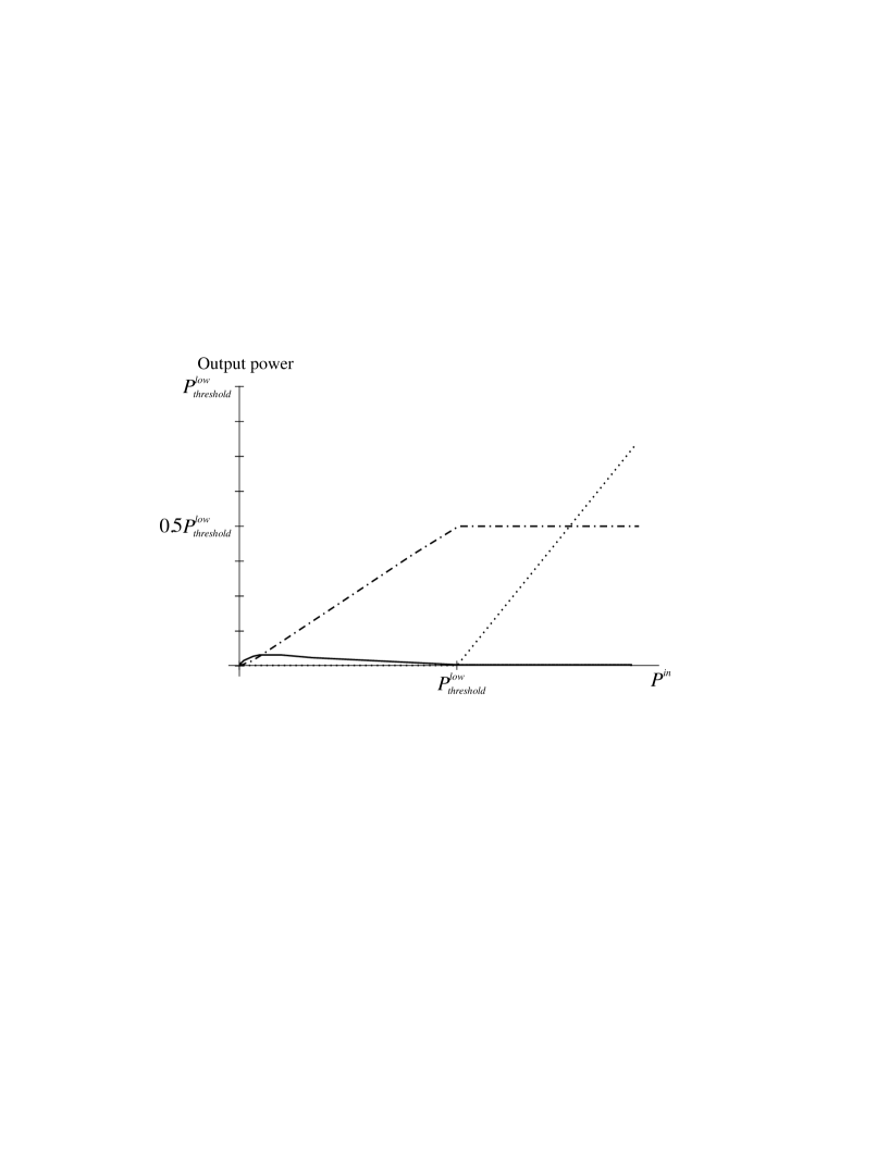
Figure 1: Intracavity pump power along the + polarization (continuous line), intracavity pump power along the - polarization, (dotted line) and intracavity second harmonic power, (dash dotted line) for the first cavity as a function of the input pump power. This is the usual behavior of an intracavity doubly resonant frequency doubler, in which more and more pump power is converted into second harmonic as the pump power increases.
-
•
For , one has , and :
(10) (11) (12) The intracavity second harmonic power is sufficient to generate an oscillation on the mode. The behavior of the system is similar to an Optical Parametric Oscillator : the second harmonic field is now clamped to its threshold value while the power increases linearly with the input power. If one uses as the output of the device the output field orthogonally polarized to the input field, and at the same frequency, , one will have a zero output below threshold, and a value rapidly growing with the input above threshold, which is the behavior that we need in our reshaping device. It is worthy to note that the present threshold , equal to for small intensity transmission coefficients at both frequencies, and , is the threshold of a triply resonant OPO, which can be in the mW range in optimized conditions 2microns .
Two difficulties must be solved to operate this device. First, we have assumed perfect triple resonance to solve the equations. This is not an easy condition to fulfill, as the fields , and see three different indices in the type II nonlinear crystal, corresponding to three different optical paths. As all the frequencies are fixed, we must then adjust precisely three parameters of the system to fulfill the triple resonance conditions. Two parameters are easily controllable : the cavity length and the crystal temperature, but a third one is needed. This last one could be the setting of a variable birefringent system in the cavity. We chose another approach, which is to insert a quarter-wave-plate (QWP) in the linear cavity, adjusted so that it induces a rotation of the polarization plane for the fundamental wave when it is crossed twice by the beam inside the cavity, and does not change the second harmonic field polarization. In this configuration, for any crystal temperature, the eigenmodes of the cavity are automatically . We need then to adjust only two parameters to ensure the triple resonance condition : the cavity length and the crystal temperature. Secondly, we have assumed a degenerate operation for the OPO. This is one possibility for the system. But a non-degenerate operation of the OPO can also take place, with signal and idler modes oscillating at different frequencies and such that : . This regime of cascading has been theoretically studied theoriecascading1 ; theoriecascading2 and observed manipcascading . Actually, the system will oscillate in the regime (degenerate or non-degenerate) which has the lowest threshold. We will see in section IV.1 that one can find conditions for which it is indeed possible to observe the stable degenerate operation that is needed for reshaping without frequency change, which is necessary for practical applications. A forthcoming publication will give more precise insight into the operation of this kind of optical devices that contain at the same time second order nonlinear elements and birefringent elements.
II.2 Second optical system : a non-degenerate OPO
The second system consists of a standard, non-degenerate, triply resonant OPO. It is well known that, in a laser above threshold, the gain is clamped to its threshold value by the condition that the saturated gain must equal the losses in the steady-state regime. The same behavior occurs in an OPO, as can be seen very easily from its steady state equations, which are very similar to eqs (1-3), except that now the input power is put in the cavity on the high frequency mode :
| (13) | |||||
| (14) | |||||
| (15) |
where and are the intracavity signal and idler mode amplitudes (these two modes oscillating at different frequencies), the intracavity pump amplitude, and the input pump amplitude; , and are the amplitude reflection coefficients of the coupling mirror at the signal, idler and pump frequencies. For the pump field, one has assume that the cavity has two identical coupling mirrors, of amplitude reflection and transmission coefficients and , one used as the input, the second as the output of our optical device.
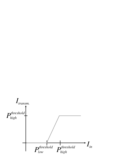
Solving these very well-known equations debuisschert , one finds that there are two different regimes, depending on the pump intensity , separated by a threshold (see figure (2)):
-
•
For , one has . No parametric oscillation takes place. The OPO cavity is a pure passive, resonant, Fabry-Perot cavity with input and output mirrors of equal transmission. Its transmission is therefore 1, and the device is exactly transparent.
-
•
For , one has and , which occurs only when , whatever the input pump field is : the intracavity pump power is therefore clamped to a value independent of the input, and the output pump field is then clamped to its value at threshold. The excess power brought by the pump is then transferred to the signal and idler beams.

Let us stress that here also, the pump threshold is the threshold of a triply resonant OPO, which can be very low. But now the system is much simpler to operate than the previous one, as the frequencies of the signal and idler modes are not a priori given (except that their sum is equal to the pump frequency). There is one more degree of freedom than in the first device, and the cavity length and crystal temperature are the only two parameters that need to be adjusted to get the triply resonant condition.
II.3 Total system
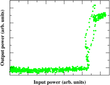
If the two previously described devices are put in series, one obtains an overall input-output characteristics which is sketched in figure (3). This curve is close to the one we need for pulse reshaping, except for the intermediate region , for which the response is linear. The best reshaping will be obtained when this central part is as steep as possible.
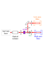
III Experimental set-up
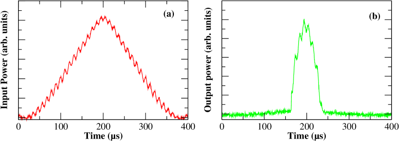
The input beam is produced by a Nd:YAG laser at (Lightwave 126-1064-700). In order to produce a light pulse, we use an acousto-optic modulator to modulate the intensity of the transmitted beam (modulation frequency ). To mimick the high frequency noise existing on the pulse, we superimpose on the enveloppe a high frequency modulation ( 100 ) and simulate the high frequency noise (fig. 4.a).
III.1 Intracavity SHG/OPO
The characteristics of the two cavities are summarized in Tab.1. The first cavity has highly reflecting mirrors both for and . The pump at is sent at a angle with respect to the crystal axis. The output beam is separated from the input by using a polarizing beam splitter in front of the optical device. At low input power, it is first converted in green light by a standard doubling process. When the intracavity green power is sufficient, parametric down conversion occurs which transfers the power back to the pump wavelength but on the orthogonal polarization. However, this system has a high threshold, above in our experimental conditions. In order to reduce his threshold, we have added a quarter waveplate at inside the cavity. In that case, we observed a much more efficient intracavity second harmonic generation, and a parametric oscillation threshold could be as low as 300 . This fairly large threshold is mainly due to the fact that the reflection coefficients were not optimized (in particular, the green reflection coefficients should be maximum which is not the case).
| Crystal | Cavity length () | Input Mirror | End Mirror | |||||
|---|---|---|---|---|---|---|---|---|
| Rλ | R2λ | Rλ | R2λ | |||||
| Cavity 1 nm | KTP | 50 | 50 | 99.9% | 95% | 50 | 90% | 99.9% |
| Cavity 2 nm | PPLN | 65 | 30 | 87% | 99.8% | 30 | 99.8% | 99% |
III.2 Non-degenerate OPO
This system has been described extensively in a previous publication 2microns ; sqpompe . Let us briefly mention here its main features : A PPLN crystal with an inversion period of 30 is placed inside a symmetric cavity which has a large finesse (over 200) for the wavelengths around and a lower finesse at (around 40). The crystal temperature is kept close to the degeneracy temperature (parametric conversion between and ) so that parametric oscillation occurred for all cavity lengths within a pump resonance, because of the overlap between the oscillation ranges of nearby signal and idler pairs of modes of wavelengths close to 2microns . The threshold was on in the order of a few . This threshold was chosen to obtain a transmitted field as close as possible to a square function : its value is much lower than the maximum intensity at the output of the first cavity to ensure a steep transmission function. Let us also mention that in our experiment, the input and output mirrors for the beam where not of equal transmission. As a result the power of the transmitted beam was very small compared to the input one, and not equal, as in the theoretical approach of the previous section. This is due to the fact that we used, instead of an optimized cavity, an existing one as used in the experiment described in ref 2microns .
IV Experimental results
IV.1 Intracavity SHG/OPO
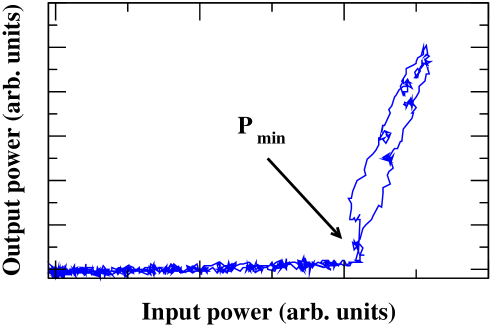
Fig. 4 shows the input and output intensities of the first device as a function of time. The maximum input power on this cavity was 350 in order to be above the threshold mentioned above. It can be seen on fig. 5 that the effect of the cavity is close to a perfect ”high-pass filter”, as far as intensities are concerned : powers below are not transmitted while those above this value are linearly transmitted.
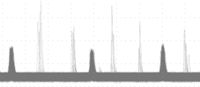
A crucial point of the device is that the output beam (orthogonally polarized reflected pump beam) is at the same frequency as the input beam. In a first experiment, we looked at the interference pattern between the input and the output beam, and observed that there were no fringes when the second harmonic beam was not . Clear fringes only appeared when, by a careful alignment and crystal temperature tuning, the green output was . The frequency degenerate operation was corroborated by a second experiment, where we used a confocal Fabry-Perot cavity to monitor the frequency of the output beam, orthogonally polarized with respect to the input beam. The confocal Fabry-Perot cavity is formed by two curved mirrors with radius of 50 and reflectivity of 95% for that the free spectral range is 1.5 . Figure 6 shows the output beam and the pump beam transmitted intensities through the confocal Fabry-Perot cavity when scanning the analysis cavity at and scanning the self pumped OPO at 650Hz : this figure shows that, when the system is not perfectly tuned up, it oscillates in a non-degenerate regime and generates sidebands around the pump frequency (fig. 6, left), whereas one can find experimental conditions for which the down-converted output has the same frequency as the pump, within the experimental uncertainties (fig. 6, right).
IV.2 Non degenerate OPO
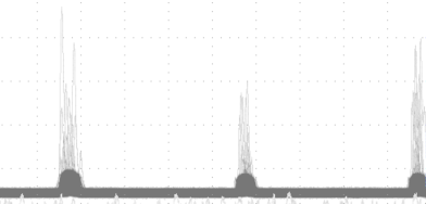
We have plotted on fig. 7 the relevant intensities for the second cavity as a function of time : 7.a shows the incident intensity, while 7.b shows the transmitted intensity. The output intensity displays a very clear clamping of the power above the threshold , at a value equal to the transmitted pump power at threshold, typically a few . On fig. 8, the ”low-pass filter” (for intensities) effect of this cavity is shown via its transfer function.
The peak that one observes at the beginning of the flat top of the transmitted intensity is due to a dynamical effect of delayed bifurcation that has already been observed in OPOs when their pump power is scanned with time richy . As the incoming pump power increases above threshold, the onset of the oscillation is delayed by a time interval that is larger than the characteristic evolution times of the cavity.
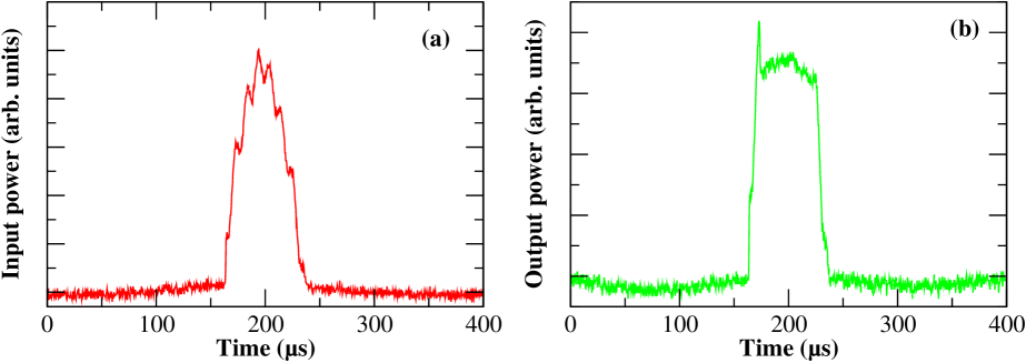
IV.3 Total cascaded system
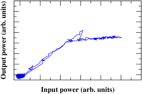
The complete experimental set-up is shown on fig 9. The beam reflected by the intracavity SHG/OPO is separated from the input beam by a polarizing beam splitter and sent to the non-degenerate OPO. The output beam intensity and the experimental transfer function for the total system are shown on fig. 10. One observes that the time dependence of the output beam intensity is close to a rectangular pulse, and accordingly that the transfer function shows the desired behavior with a response very close to a step function.
V Possible implementation to very high bit rates at
In all-optical pulse reshaping systems, two parameters play an important role : the operating power and the response time. In the present demonstration experiment, the incident power on the first cavity is about 350 , which is beyond the current powers of optical telecommunication pulses. This is mainly due to the fact that the first cavity is not optimized. Thresholds in the range of tens of could be obtained by using high quality materials and coatings and optimizing the cavity parameters. The response time of our present system is rather long, of the order of 200 : it is related to the cavity build-up time of the two cavities which are long cavities with rather high finesses. The most important question for the future of our proposed technique is whether our system can be modified and optimized in order to be able to reach very high bit rates, namely 40 , and at the telecommunication wavelength of . We will address this question in the present section.
Several nonlinear materials are compatible with the telecommunication wavelength, namely Gallium Arsenide, Aluminium Gallium Arsenide, or Zinc Selenide. These materials posses very large nonlinearities, as large as in the case of Gallium Arsenide but they cannot be phase matched using birefringence.
The rising time issue is the most difficult to solve. In order to reduce this time, one must use small cavities, and therefore shorter non-linear crystals, and/or lower reflectivities for the mirrors, two methods which have the detrimental effect of increasing the thresholds at the same time.
The threshold of a triply resonant OPO is given by
| (16) |
where denotes the transmission coefficient of the cavity for mode , the crystal length and is the non linear coupling strength depending on the nonlinearity, geometry and optical indices through the relation :
| (17) |
where is the crystal nonlinearity in , is the waist size, is the pulsation and the indices of refraction of the three interacting modes. Assuming the system is operated close to frequency degeneracy, that is and that the pump, signal and idler indices and Rayleigh ranges are identical, the nonlinear coupling strength can be expressed in terms of wavelength and Rayleigh length, as :
| (18) |
where the index denotes experimental values, , denote the pump wavelength in the vacuum, these two wavelengths being different due to the fact that our experiment was performed with a pump while a telecom implementation would require .
If we also assume that the cavity length is equal to the crystal length, one can use the expression for the finesse as a function of the cavity rise time
| (19) |
We now obtain the following formula for the ratio of the thresholds :
| (20) |
One obtains a counterintuitive result, namely that the threshold becomes lower as the crystal/cavity length diminishes. This is due to the fact that the finesse is fixed by the value of the cavity length in order to keep the cavity lifetime constant. A small cavity is thus desirable to obtain a low threshold as well as a short rise time. The experimental values correspond to an optimized cavity containing a KTP crystal pumped by a frequency doubled Nd:YAG laser at 532 generating signal and idler around 1064 yielding with , , , . When one sets a cavity/crystal length of 10, a rise time of (compatible with operating bit rate of 40 GBit/s), and a Rayleigh length of 10 compatible with the crystal length, one obtains a finesse and threshold with the values corresponding to gallium arsenide ( and ). This value of the threshold is compatible with the values used in optical telecommunications. The very short length of the crystal is also an advantage as one can have a crystal length equal to or shorter than the coherence length of the material which partly removes the problem of phase-matching. It is important to note that the variation of the threshold with is very fast so that a small increase of the rise time up to 15 leads to a similar threshold using Lithium Niobate ( and ).
We have shown in this section that the realization of very short rise time systems for all optical reshaping is within reach by developing current techniques and using available materials. However, because of the presence of the resonance cavity, this system is only able to reshape optical pulses centered around a given wavelength.
VI Conclusion
We have demonstrated that optical cavities containing media can be used for all optical passive reshaping of optical pulses. We have experimentally obtained reshaping with a threshold compatible with optical powers propagating in optical fibers. We have shown that very fast response times can be realized using very short monolithic cavities made of high nonlinearity crystals.
Acknowledgements.
Laboratoire Kastler-Brossel, of the Ecole Normale Supérieure and the Université Pierre et Marie Curie, is associated with the Centre National de la Recherche Scientifique. This work was supported by France-Telecom (project CTI n∘ 98-9.003). Zhang Kuanshou was on leave from the Key Laboratory for Quantum Optics, Shanxi University, Taiyuan, China. T. Coudreau is also at the Pôle Matériaux et Phénomènes Quantiques FR CNRS 2437. The authors want to thank V. Berger for fruitful discussions.References
- (1) J. Simon, L. Billes, A. Dupas, B. Kowalski, M. Henry, B.Landousies, ”All-optical regeneration”, ECOC’98, Madrid, Spain, 467 (1998);
- (2) J. Lucek, K. Smith, ”All-optical signal regenerator”, Opt. Lett. 18, 1226-1228 (1993)
- (3) T. Debuisschert, A. Sizmann, E. Giacobino, C. Fabre, ”Type-II continuous-wave optical parametric oscillators: oscillation and frequency-tuning characteristics”, J. Opt. Soc. Am. B10, 1668-1680 (1993)
- (4) Z.Y. Ou,”Quantum-nondemolition measurement and squeezing in type-II harmonic generation with triple resonance” Phys. Rev. A 49, 4902-4911 (1994)
- (5) U. Peschel, C. Etrich, F. Lederer, ”Symmetry breakingand self-oscillations in intracavity vectorial second- harmonicgeneration”, Opt. Lett. 23, 500-502 (1998)
- (6) M Martinelli, K S Zhang, T Coudreau, A Maître and C Fabre, “Ultra-low threshold CW triply resonant OPO in the near infrared using periodically poled lithium niobate”, J. Opt. A : Pure and Appl. Opt. 3 300-303 (2001).
- (7) S. Schiller, R. Bruckmeier, A. White, “Classical and quantum properties of the subharmonic-pumped parametric oscillator”, Opt. Commun. 138, 158-171 (1997)
- (8) A. G. White, P. K. Lam, M. S.Taubman, M. A. M. Marte, S. Schiller, D. E. McClelland, H.A. Bachor, “Classical and quantum signatures of competing nonlinearities”, Phys. Rev. A55, 4511-4515 (1997)
- (9) K. Schneider and S. Schiller, “Multiple conversion and optical limiting in a subharmonic-pumped parametric oscillator”, Opt. Lett. 6, 363-365 (1997)
- (10) K. S. Zhang, T. Coudreau, M. Martinelli, A. Maître, and C. Fabre, “Generation of bright squeezed light at 1.06 using cascaded nonlinearities in a triply resonant cw periodically-poled lithium niobate optical parametric oscillator”, Phys. Rev. A 64, 033815 1-6 (2001)
- (11) C. Richy, K. I. Petsas, E. Giacobino, C. Fabre, L. Lugiato, “Observation of bistability and delayed bifurcation in a triply resonant optical parametric oscillator”, J. Opt. Soc. Am. B 12, 456-461 (1995)