Two Means of Compensating Fiber Nonlinearity
Using Optical Phase Conjugation
Haiqing Wei∗ and David V. Plant
Department of Electrical and Computer Engineering
McGill University, Montreal, Canada H3A-2A6
∗hwei1@po-box.mcgill.ca
Abstract
Two fiber lines may compensate each other for nonlinearity with the help of optical phase conjugation. The pair of fiber lines and the optical signals in them may be either mirror-symmetric or translationally symmetric about the conjugator.
© 2024 Optical Society of America
OCIS codes: (060.2330) Fiber optics communications; (190.4370) Nonlinear
optics, fibers
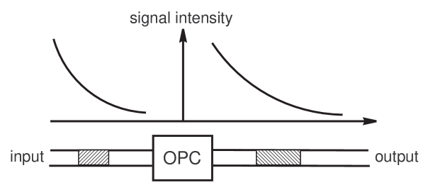
The growing demand of higher capacity over longer transmission distances has seen fiber nonlinearity as a major limiting factor in modern optical transmission systems [1, 2]. Among the methods under investigation, nonlinearity compensation using optical phase conjugation (OPC) has emerged as an effective means of suppressing the nonlinear impairments [3, 4, 5]. This paper shall discuss two types of fiber arrangement with respect to the OPC, as shown in Fig.1. In one type of arrangement, the fiber parameters and the signal intensity are in scaled mirror symmetry about the OPC. While the other type is characterized by scaled translational symmetry.
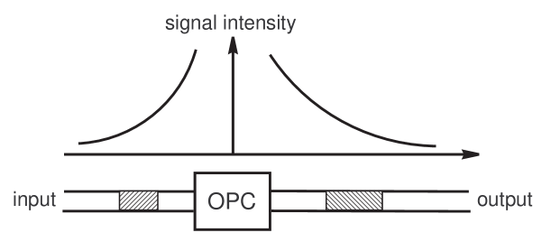
A mirror-symmetric link may consist of a fiber line on the left stretching from to , , , followed by an OPC, then a fiber line on the right stretching from to . The two fiber lines may carry wavelength-division multiplexed (WDM) signals and respectively, where , and are the center frequencies of the WDM channels, , is not necessarily equal to , and are the slow-varying envelopes, while and are the -dependent propagation constants. Being neglected is the random polarization-mode dispersion (PMD) effect. And for mathematical simplicity, all optical signals are assumed co-linearly polarized in the fibers. Define short-hand notations , and , . The dynamics of signal propagation in the two fiber lines is governed by two groups of coupled partial differential equations [5, 6, 7] respectively,
| (1) | |||
| (2) |
, where for the first fiber line, is the attenuation coefficient around , is the Kerr nonlinear coefficient, is the Raman coupling coefficient from the th to the th channels, is the phase mismatch among the mixing waves, and the functional operator is defined as . The parameters , , , and the operator are similarly defined for the second fiber line. It is an easy exercise to show that equations (1) reduce to (2), when the parameters satisfy the following rules of correspondence,
| (3) | |||||
| (4) | |||||
| (5) | |||||
| (6) |
, being a constant, and the envelope functions are related as , . Physically, it says that the two fiber lines compensate each other for dispersion and nonlinearity. Optical signals , , entering the first fiber line may be dispersed and nonlinearly distorted to become , , which are converted into , , by the OPC. The second fiber line will then propagate the optical signals in a reversed manner with respect to the first. The final outputs signals , , are exact replicas of the initial signals up to complex conjugation. It is noted that parts of one fiber line would amplify light in correspondence to the attenuation in parts of the other, and vice versa. A specialty fiber may be chosen with parameters satisfying equations (3,5,6) to be the scaled mirror image of a transmission fiber which usually attenuates light. At the same time, erbium doping or Raman pumping should be employed to obtain the gain specified by (4).
A link with translational symmetry could be constructed to cancel weak nonlinearities up to the first order perturbation. Consider two fiber lines with opposite Kerr and Raman nonlinear coefficients but identical linear parameters. If (1) with describe the signal propagation in one fiber line, then the signal dynamics in the other would be governed by similar equations with negative and coefficients,
| (7) |
which take the input , and give the output , . When the signal intensity is not very high, so that the nonlinearity is weak and treated with perturbation theory, the output from each fiber line is a linearly dispersed version of the input, plus nonlinear distortions expanded in power series of the and coefficients. By neglecting the higher order powers and keeping only the terms linear in or , it can be seen that the two fiber lines induce opposite nonlinear distortions to otherwise the same, linearly dispersed signals. If the overall dispersion of each line is compensated to zero and the signal loss is made up by a linear optical amplifier, then the two lines in cascade would comprise a transmission line with fiber nonlinearity annihilated up to the first order perturbation. The problem is that an optical fiber with negative nonlinear coefficients does not exist naturally. Fortunately, it can be simulated by a regular fiber with the help of OPC. Take a regular fiber with parameters that satisfy,
| (8) | |||||
| (9) | |||||
| (10) | |||||
| (11) |
. The signal propagation in the regular fiber is then governed by,
| (12) |
, which are solved by , , and turn the input , , into the output , . The regular fiber equipped with OPC at its two ends takes the input , and gives the output , . That fulfils the function of the fictitious fiber with negative nonlinearity. The OPC at the output end of the regular fiber may be omitted in practice, as most applications would not differentiate between a signal and its conjugate.
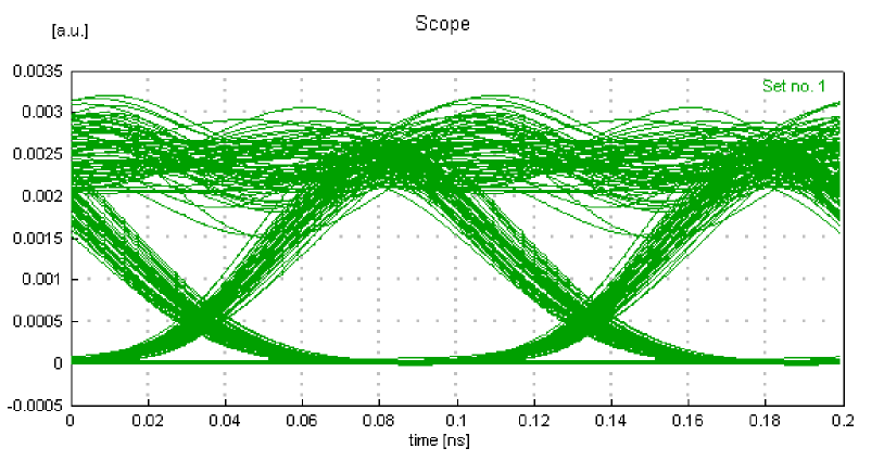
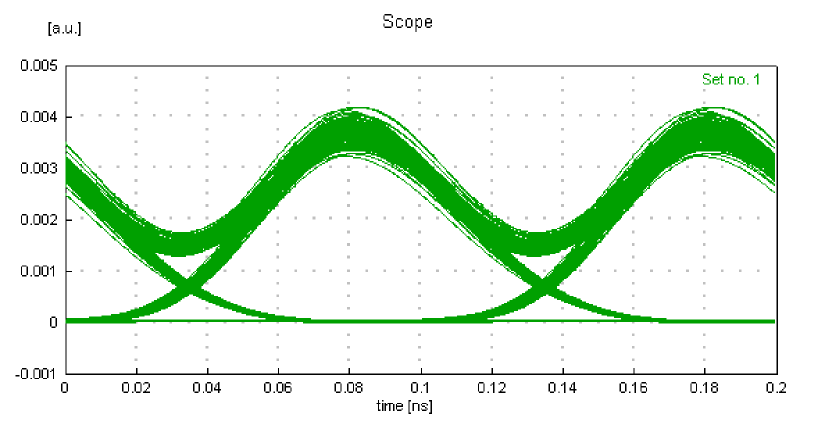
It is noted that each fiber line on one side of the OPC is not necessarily one fiber span, and the signal intensity does not have to evolve monotonically either. Both methods work fine when each side of the OPC consists of multiple fiber spans with optical amplifiers boosting the signal power, although the added noise makes perfect nonlinearity compensation impossible. Using a commercial software, computer simulations have been carried out to test the proposed methods of nonlinearity compensation. For the mirror setup, the test link consists of a specialty fiber, an OPC, and a transmission fiber km long, with loss dB/km, dispersion ps/nm/km, dispersion slope ps/nm2/km, effective mode area m2, Kerr and Raman coefficients that are typical of silica glass. The specialty fiber is made of the same material, but with parameters and m2. The nonlinearity of the specialty fiber can be switched on and off. Amplifier noise is added at the two ends of the link. The input are four WDM channels spaced by GHz, return-to-zero modulated at Gb/s with duty. The pulses peak at mW when entering the transmission fiber. For a WDM system with the span loss so large and the input optical power so high, the output signals would be distorted heavily and become unusable, were there no nonlinearity compensation [8]. By contrast, the transmission system becomes virtually penalty-free with our scheme of mirror-symmetric nonlinearity compensation [8]. The test system in translational symmetry is constructed with ten -km spans on one side of the OPC using the same transmission fiber as in the mirror setup. Each span is ended by an erbium-doped fiber amplifier (EDFA) with dB gain, noise figure dB, and a dispersion compensating module (DCM) with negligible nonlinearity. The DCM perfectly compensates the and of the fiber span. On the other side of the OPC are ten spans of transmission fiber with parameters . The loss and dispersion of each span are also fully compensated by an EDFA and a DCM. The EDFA noise figure is still dB. The input RZ pulses peak at 10 mW when entering the transmission fiber. Firstly, the OPC is absent and the transmission result of the 20-span link is shown in the left-side graph of Fig.2. When the OPC is put back, the other graph in Fig.2 clearly demonstrates the effect of nonlinearity compensation.
References
- [1] F. Forghieri, R. W. Tkach and A. R. Chraplyvy, “Fiber nonlinearities and their impact on transmission systems,” in Optical Fiber Telecommunications III A, I. P. Kaminow and T. L. Koch, eds. Academic Press: San Diego, 1997.
- [2] P. P. Mitra and J. B. Stark, “Nonlinear limits to the information capacity of optical fiber communications,” Nature, vol. 411, pp. 1027-1030, June 2001.
- [3] S. Watanabe and M. Shirasaki, “Exact compensation for both chromatic dispersion and Kerr effect in a transmission fiber using optical phase conjugation,” J. Lightwave Techn., vol. 14, no. 3, pp. 243-248, 1996.
- [4] I. Brener, B. Mikkelsen, K. Rottwitt, W. Burkett, G. Raybon, J. B. Stark, K. Parameswaran, M. H. Chou, M. M. Fejer, E. E. Chaban, R. Harel, D. L. Philen, and S. Kosinski, “Cancellation of all Kerr nonlinearities in long fiber spans using a LiNbO3 phase conjugator and Raman amplification,” OFC’00, post-deadline paper, PD33, Baltimore, Maryland, 2000.
- [5] H. Wei and D. V. Plant, “Does fiber nonlinearity really limit the capacity of optical channels?” OFC’03.
- [6] Y. R. Shen, The Principles of Nonlinear Optics. New York: John Wiley & Sons, 1984.
- [7] G. P. Agrawal, Nonlinear Fiber Optics, 2nd ed. San Diego: Academic Press, 1995.
- [8] H. Wei and D. V. Plant, “On the Capacity of Nonlinear Fiber Channels,” arXiv:physics/0307020 at http://arxiv.org/, July 2003.