Muon Cooling Research and Development
Abstract
The MuCool R&D program is described. The aim of MuCool is to develop all key pieces of hardware required for ionization cooling of a muon beam. This effort will lead to a more detailed understanding of the construction and operating costs of such hardware, as well as to optimized designs that can be used to build a Neutrino Factory or Muon Collider. This work is being undertaken by a broad collaboration including physicists and engineers from many national laboratories and universities in the U.S. and abroad. The intended schedule of work will lead to ionization cooling being well enough established that a construction decision for a Neutrino Factory could be taken before the end of this decade based on a solid technical foundation.
IIT-HEP-03/2
1 Introduction
The possibility of building a muon accelerator has received much attention in recent years [1, 2, 3, 4]. In particular, decay neutrinos from a stored high-energy muon beam [5] may well provide the ultimate tool for the study of neutrino oscillations [6] and their possible role in baryogenesis via CP-violating neutrino mixing [7]. The goal for such a Neutrino Factory is neutrinos/year (requiring a similar number of muons/year stored in the ring).
Muon beams at the required intensity can only be produced into a large phase space, but affordable existing acceleration technologies require a small input beam. This mismatch could be alleviated by developing new, large-aperture, acceleration techniques [8], by “cooling” the muon beam to reduce its size, or both. Given the 2.2-s muon lifetime, only one cooling technique is fast enough: ionization cooling, in which muons repeatedly traverse an energy-absorbing medium, alternating with accelerating devices, within a strongly focusing magnetic lattice [9, 10, 11, 12]. The main focus of the MuCool Collaboration [13] has been development of hardware devices and systems that can be used for ionization cooling of a muon beam.
2 Ionization cooling channels: design considerations
In an ionization-cooling channel, ionization of the energy-absorbing medium decreases all three muon-momentum components without affecting the beam size. This constitutes cooling (reduction of normalized emittance) since the reduction of each particle’s momentum results in a reduced transverse-momentum spread of the beam as a whole. If desired, a portion of this transverse cooling effect can be rotated into the longitudinal phase plane by inserting suitably shaped energy absorbers into dispersive regions of the lattice (“emittance exchange”); longitudinal ionization cooling per se is impractical due to energy-loss straggling [11].
Within an absorber the rate of change of normalized transverse emittance is given approximately by [9, 10, 14]
| (1) |
Here angle brackets denote mean value, is the muon velocity in units of , muon energy is in GeV, is the lattice beta function evaluated at the location of the absorber, is the muon mass in GeV/, and is the radiation length of the absorber medium.
The two terms of Eq. 1 reflect the competition between multiple Coulomb scattering of the muons within the absorber (a heating effect) and ionization energy loss. This favors low- absorber materials, the best being hydrogen (see Table 1). Since the heating term is proportional to , the heating effect of multiple scattering is minimized by maximizing the focusing strength of the lattice at the location of the absorbers. Superconducting solenoids are thus the focusing element of choice in most design studies and can give cm. The combined effect of the heating and cooling terms sets an equilibrium emittance at which the cooling rate goes to zero and beyond which a given lattice cannot cool.
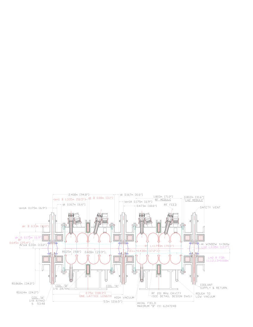
Between absorbers, high-gradient acceleration of the muons must be provided to replace the lost longitudinal momentum, so that the ionization-cooling process can be repeated many times. Ideally, this acceleration should exceed the minimum required for momentum replacement, allowing “off-crest” operation. This gives continual rebunching, so that even a beam with large momentum spread remains captured in the rf bucket. Even though it is the absorbers that actually cool the beam, for typical accelerating gradients (10 MeV/m, to be compared with MeV/m for liquid hydrogen [15]), the rf cavities dominate the length of the cooling channel (see e.g. Fig. 1). The achievable rf gradient thus determines how much cooling is practical before an appreciable fraction of the muons have decayed or drifted out of the bucket.
In spite of the relativistic increase of muon lifetime with energy, ionization cooling favors low beam momentum, both because of the increase of for momenta below the ionization minimum [15] and since less accelerating voltage is then required. Most Neutrino Factory and Muon Collider beam-cooling designs and simulations to date have used momenta in the range MeV/. (This is also the momentum range in which the pion-production cross section off of thick targets tends to peak and is thus optimal for muon production as well as cooling.) The cooling channel of Fig. 1 is optimized for a mean muon momentum of 200 MeV.
As a muon beam passes through a transverse ionization-cooling lattice, its longitudinal emittance tends to grow, due to such effects as energy-loss straggling. The six-dimensional emittance typically is reduced despite this longitudinal heating. However, if not controlled, the longitudinal heating leads to beam losses and thus limits the degree of transverse cooling that is practical to achieve. Cooling lattices with longitudinal–transverse emittance exchange (e.g., ring coolers), which can cool in all six dimensions simultaneously, have been receiving increasing attention [16, 17]. They have the potential to increase Neutrino Factory performance and decrease cost, and are essential to achieving sufficient cooling for a Muon Collider.
3 Muon-cooling technology development
An effective ionization-cooling channel must include low- absorbers with (if an intense muon beam is to be cooled) high power-handling capability. To achieve low beta at the absorbers requires either high solenoidal magnetic field or high field gradient [18]. To pack as much cooling as possible into the shortest distance requires the highest practical accelerating gradient. The MuCool Collaboration has embarked on R&D on all three of these technologies.
3.1 High-power liquid-hydrogen absorbers
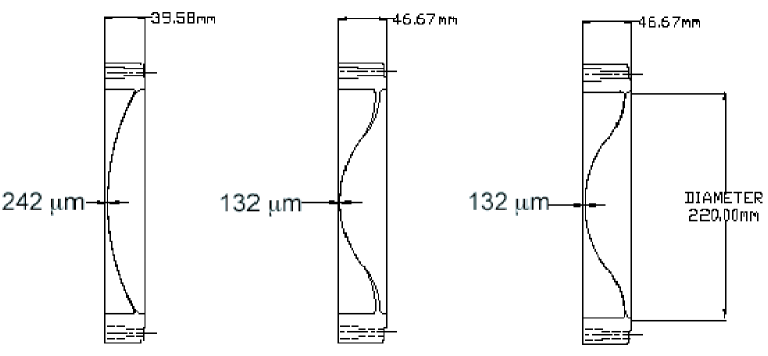
The development of high-power liquid-hydrogen (LH2) absorbers with thin windows has been a key goal of the MuCool R&D program [19, 20, 21]. Simulations as well as theory show that scattering in absorber windows degrades muon-cooling performance. (This is especially true for ring coolers, in which the muons circulate until they approach the equilibrium emittance dictated by multiple scattering.) We have therefore developed new shapes for the ends of the hydrogen flasks (Fig. 2) that allow significant reduction in their thickness (especially near the center where the beam intensity is maximum). We have successfully fabricated such tapered, curved windows out of disks of aluminum alloy using a numerically controlled lathe. We have also devised novel means [22] to test these nonstandard windows and demonstrate that they meet their specifications and satisfy the applicable safety requirements [21]. By optimizing the maximum stress as a function of pressure, the “thinned bellows” shape of Fig. 2 gives a central window thickness about one-quarter that of an ASME-standard “torispherical” window [23].
Fabrication (and destructive testing as mandated by the Fermilab safety code [24]) of “tapered torispherical” windows (Fig. 2) was successfully accomplished previously [21], using the 6061-T6 alloy that is standard in cryogenic applications. Fabrication of a series of “thinned bellows” windows is currently underway. We are also exploring the use of lithium–aluminum alloys, such as the 2195 alloy used in the Space Shuttle (80% stronger than 6061-T6); the resulting thinness of the window may challenge our fabrication techniques, and we will need to certify the new alloy for machinability and high-radiation application.
The W of power dissipated in these absorbers (in Feasibility Study II at least) is within the bounds of high-power liquid-hydrogen targets developed for, and operated in, a variety of experiments [25]. However, the highly turbulent fluid dynamics involved in the heat-exchange process necessarily requires R&D for each new configuration. We have identified two possible approaches: a “conventional” flow-through design with external heat exchanger, similar to that used for high-power LH2 targets, and a convection-cooled design, with internal heat exchanger built into the absorber vessel. The convection design has desirable mechanical simplicity and minimizes the total hydrogen volume in the cooling channel (a significant safety concern), but is expected to be limited to lower power dissipation than the flow-through design. To study and optimize the fluid mixing and heat transfer properties of these absorber designs, we have been exploring ways to visualize the flow patterns and temperature distributions within the fluid [26] and test the predictions of numerical flow simulations [27]. To keep window thicknesses to a minimum, both designs operate just above 1 atm of pressure.
Various scenarios have been discussed involving substantially higher absorber power dissipation: 1) a Neutrino Factory with a more ambitious Proton Driver (4 MW proton-beam power on the pion-production target instead of the 1 MW assumed in Study-II) is a relatively straightforward and cost-effective design upgrade [1], 2) the “bunched-beam phase rotation” scenario of Neuffer [28] captures and simultaneously, doubling the absorber power dissipation, and 3) a ring cooler [16] would entail multiple traversals of each absorber by each muon, potentially increasing absorber power dissipation by an order of magnitude. If all three of these design upgrades are implemented, power dissipations of tens of kilowatts per absorber will result. The large heat capacity of hydrogen means that such levels of instantaneous power dissipation are in principle supportable, but much higher average heat transfer would be needed, possibly requiring higher operating pressure and thicker windows. More work is needed to assess the muon-cooling performance implications.
3.2 Other absorber materials
Other candidate absorber materials include helium, lithium, lithium hydride, methane, and beryllium. All other things being equal, in principle these would all give worse cooling performance than hydrogen. For fixed , a possible figure of merit is (proportional to the four-dimensional transverse-cooling rate), normalized to that of liquid hydrogen. Table 1 shows that hydrogen is best by a factor , although its advantage could be vitiated if thick windows are necessary. Furthermore, for sufficiently high focusing-current density, lithium lenses could provide substantially lower than is practical with solenoids [10, 11], perhaps sufficient to overcome lithium’s disadvantageous merit factor. Liquids provide high power-handling capability, since the warmed liquid can be moved to a heat exchanger. On the other hand, the higher densities of solids allow the absorber to be located more precisely at the low-beta point of the lattice. Lithium hydride may be usable with no windows, but means would have to be devised to prevent combustion due to possible contact with moisture, as well as to avoid melting at high power levels. More work will be required to assess these issues in detail.
It has been pointed out [19, 29] that gaseous hydrogen (GH2) at high pressure could provide the energy absorption needed for ionization cooling, with significantly different technical challenges than those of a liquid or solid absorber. Table 1 shows that GH2 is actually a slightly better ionization-cooling medium than LH2. In addition, if the hydrogen is allowed to fill the rf cavities, the number of windows in the cooling channel can be substantially reduced, and the length of the channel significantly shortened. Moreover, filling the cavities with a dense gas can suppress breakdown and field emission, via the Paschen effect [30]. A small business [31] has been formed to pursue this idea, with funding from the U.S. Dept. of Energy’s Small Business Technology Transfer program [32]. Phase I of this program has been completed and included tests of breakdown in gaseous helium and hydrogen at 805 MHz, 77 K temperature, and pressures from 1 to 50 atm; gradients as high as 50 MV/m have been achieved [33]. If approved, a follow-on Phase II will explore operation at lower frequency. Successful completion of this program could lead to construction of a prototype gaseous-absorber cooling cell, to be tested at the MuCool Test Area (described below) and perhaps in a future phase of the Muon Ionization Cooling Experiment (MICE) [34]. Other applications for gas-filled rf cavities have also been proposed, including rf pulse compression and six-dimensional cooling [17].
3.3 High-gradient normal-conducting rf cavities
An ionization-cooling channel requires insertion of high-gradient rf cavities into a lattice employing strong solenoidal magnetic fields. This precludes the use of superconducting cavities. The lattice of Fig. 1 employs normal-conducting 201-MHz cavities, but R&D is more readily carried out with smaller, higher-frequency devices.
Radio-frequency cavities normally contain a minimum of material in the path of the beam. However, the penetrating character of the muon allows the use of closed-cell (“pillbox”) cavities, provided that the cell closures are constructed of thin material of long radiation length. Eq. 1 implies that this material will have little effect on cooling performance as long as its thickness per cooling cell (at the of its location in the lattice) has small compared to that of an absorber. Closing the rf cells approximately doubles the on-axis accelerating gradient for a given maximum surface electric field, allowing operation with less rf power and suppressing field emission. Two alternatives have been considered for the design of the cell closures: thin beryllium foils and grids of gas-cooled, thin-walled aluminum tubing. As a fall-back, an open-cell cavity design was also pursued.
So far we have prototyped and tested a 6-cell open-cell cavity, designed at Fermilab, and a single-cell closed-cell cavity, designed at LBNL, both at 805 MHz. The tests are carried out in Fermilab’s Laboratory G, where we have installed a high-power 805-MHz klystron transmitter (12-MW peak pulsed power with pulse length of 50 s and repetition rate of 15 Hz), an x-ray-shielded cave, remote-readout test probes, safety-interlock systems, and a control room and workshop area for setup of experiments. The cave also contains a high-vacuum pumping system and water cooling for the cavity. To allow tests of the cooling-channel rf cavities and absorbers in a high magnetic field or high field gradient, a superconducting 5-T solenoid with a room-temperature bore of 44 cm was constructed by LBNL and installed in Lab G, with two separate coils that can be run in “solenoid” mode (currents flowing in the same direction) or “gradient” mode (currents in opposite directions).
The open-cell cavity was conditioned up to a surface electric field of 54 MV/m (on-axis accelerating gradient up to 25 MV/m). Electron dark currents and x-ray backgrounds were found to be large and to scale as a high power of the surface field, [35]. With a 2.5-T solenoidal field applied, at 54-MV/m surface field, axially focused dark currents ultimately burned a hole in the cavity’s titanium vacuum window. This level of background emission would preclude cavity operation in the required solenoidal field. However, for the same accelerating gradient, the pillbox cavity operates at approximately half the surface field, corresponding to lower background emission by a factor of order . Furthermore, an analysis of the observed emission rate in terms of the Fowler-Nordheim formalism [36] implies an enhancement of the emission probability by a factor of order compared to that of a smooth, clean surface [35]. This suggests that an R&D program focused on improving the surface preparation and treatment might reap large improvements.
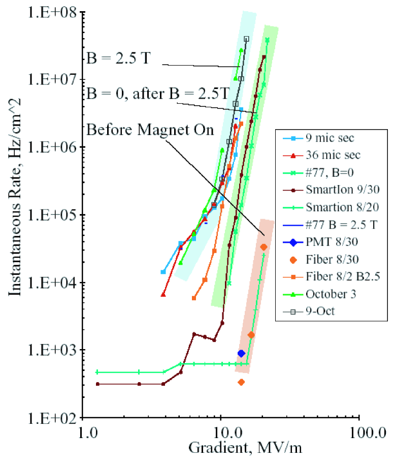
Tests of the closed-cell prototype are in progress [37]. Initial tests with 5-mm-thick copper windows up to the design gradient of 34 MV/m with no applied magnetic field were carried out successfully, with an acceptable degree of multipactoring and little or no arcing. Upon disassembly, no damage to the windows was observed. The thickness of the cavity’s vacuum windows (1.9 cm of stainless steel) precluded measurement of low-energy backgrounds. Thinner windows (380 m of Cu plus 200 m Ti vacuum windows) were then installed and operated with gradients above 20 MV/m at 2.5 T, however occasional sparking at 2.5 T gradually degraded performance. Some healing of the damage was effected by reconditioning at , but repeated cycles of damage and reconditioning established that the highest sustainable gradient at 2.5 T was 15 MV/m. Measurements of x rays and dark currents during these tests are presented in Fig. 3.
Tests were subsequently performed with TiN-coated beryllium windows. Gradients up to 18 MV/m were achieved at 4 T, but again spark damage gradually degraded performance; we also encountered some frequency instability, suggesting that the windows may have been flexing due to rf heating. When these windows were removed for inspection, blobs of copper were found deposited on the (otherwise undamaged) TiN surface. An insulating TiN coating was also observed on the mounting ring, contrary to specifications. Tests are now beginning with another set of TiN-coated Be windows having a clean electrical connection at the mounting ring.
While our experience shows that development of closed-cell, high-gradient, normal-conducting cavities for use in magnetic fields is not easy, there is as yet no reason to believe we will not ultimately be successful. Exposed copper surfaces appear to be problematic at high surface electric field. A variety of window and cavity surface preparations and coatings remain to be explored, e.g., TiN-coating the copper at the locations of maximum surface field. Alternatives to flat, prestressed foils are receiving attention as well, and we expect to prototype and test several possible solutions at 805 MHz. (Our 805-MHz pillbox-cavity prototype was designed with demountable windows with such a test program in mind.) Design studies indicate that both precurved Be foils and grids of gas-cooled, thin-walled Al tubes should be feasible and may be cheaper and induce less scattering than flat foils.
The design of a prototype 201-MHz closed-cell cavity for muon cooling is essentially complete [38]. Since the window R&D is not yet completed, the cavity design accommodates a variety of cell closures. We intend to build the first prototype in the coming year.
3.4 Test facilities
To augment the Lab G facility described above, we are building a MuCool Test Area at the end of the Fermilab Linac. This location combines availability of multi-megawatt rf power at both 805 and 201 MHz and 400-MeV proton beam at high intensity. Cryogenic facilities will be provided for liquid-hydrogen-absorber and superconducting-magnet operation. The underground enclosure under construction will provide the radiation shielding needed for beam tests of absorber power handling and for high-gradient cavity testing, with the added capability of exploring possible effects on cavity breakdown due to beam irradiation of the cavity walls in a solenoidal magnetic field. Construction of the MuCool Test Area has progressed well and we anticipate its utilization for absorber tests towards the end of 2003, as well as for tests of the prototype 201-MHz cavity when it becomes available.
The MuCool program includes engineering tests of ionization-cooling components and systems, but not an actual experimental demonstration of ionization cooling with a muon beam. Such a cooling demonstration (MICE) has been proposed and is discussed elsewhere in these Proceedings [34].
Acknowledgements
I thank the organizers for the opportunity to present this work in this remarkable and beautiful setting. This work was supported in part by the US Dept. of Energy, the National Science Foundation, the Illinois Board of Higher Education, the US-Japan Agreement on High Energy Physics, and the UK Particle Physics and Astronomy Research Council.
References
- [1] M. M. Alsharo’a et al., “Status of Neutrino Factory and Muon Collider Research and Development and Future Plans,” FNAL-PUB-02/149-E (July 19, 2002), submitted to Phys. Rev. ST Accel. Beams, arXiv:hep-ex/0207031.
- [2] See e.g. the Proceedings of the NuFact Workshop series: NuFact’99, B. Autin, ed., Nucl. Instrum. Meth. A451 (2000) 1-388; NuFact’00, S. Chattopadhyay, ed., Nucl. Instrum. Meth. A472 (2001) 323-666; NuFact’01, to appear in Nucl. Instr. Meth. A (2003); NuFact’02, K. Long ed., to appear in J. Phys. G; and many articles too numerous to list here.
- [3] “Feasibility Study on a Neutrino Source Based on a Muon Storage Ring,” D. Finley, N. Holtkamp, eds. (2000), http://www.fnal.gov/projects/muon_collider/reports.html.
- [4] “Feasibility Study-II of a Muon-Based Neutrino Source,” S. Ozaki, R. Palmer, M. Zisman, and J. Gallardo, eds., BNL-52623, June 2001, available at http://www.cap.bnl.gov/mumu/studyii/FS2-report.html.
- [5] S. Geer, Phys. Rev. D 57, 6989 (1998); earlier versions of a Neutrino Factory, considered by e.g. D. G. Koshkarev, report CERN/ISR-DI/74-62 (1974), S. Wojicki (unpublished, 1974), D. Cline and D. Neuffer, AIP Conf. Proc. 68, 846 (1981), and D. Neuffer, IEEE Trans. Nucl. Sci. 28, 2034 (1981), were based on pion injection into a storage ring and had substantially less sensitivity.
- [6] C. Albright et al., Fermilab-FN-692 (May, 2000), hep-ex/0008064; M. Apollonio et al., CERN-TH-2002-208 (Oct. 2002.), hep-ph/021019; M. Lindner, hep-ph/0209083 (2002).
- [7] See e.g. M. Pluemacher, to appear in Proc. NuFact’02, op. cit., and references therein.
- [8] “A Feasibility Study of A Neutrino Factory in Japan,” Y. Kuno, ed., available from http://www-prism.kek.jp/nufactj/index.html; Y. Mori, “Review of Japanese Neutrino Factory R&D,” A. Sato, “Beam dynamics studies of FFAG,” D. Neuffer, “Recent FFAG studies,” S. Machida, “Muon Acceleration with FFAGs,” and C. Johnstone, “FFAG with high frequency RF for rapid acceleration,” to appear in Proc. NuFact’02, op. cit.
- [9] A. N. Skrinsky and V. V. Parkhomchuk, Sov. J. Part. Nucl. 12, 223 (1981); E. A. Perevedentsev and A. N. Skrinsky, in Proc. 12th Int. Conf. on High Energy Accelerators, F. T. Cole and R. Donaldson, eds. (Fermilab, 1984), p 485; R. Palmer et al., Nucl. Phys. Proc. Suppl. 51A, 61 (1996).
- [10] D. Neuffer, Part. Acc. 14, 75 (1983).
- [11] D. Neuffer, this Workshop.
- [12] Introductory discussions of muon ionization cooling may be found in [11] and D. M. Kaplan, in Proc. APS/DPF/DPB Summer Study on the Future of Particle Physics (Snowmass 2001), N. Graf, ed., arXiv:physics/0109061 (2002). More detailed treatments may be found in D. Neuffer, “ Colliders,” CERN yellow report CERN-99-12 (1999), K. J. Kim and C. X. Wang, Phys. Rev. Lett. 85, 760 (2000), and C. X. Wang and K. J. Kim, “Linear theory of 6-D ionization cooling,” in Proc. Snowmass 2001, op. cit., SNOWMASS-2001-T502 (2001).
- [13] See http://www.fnal.gov/projects/muon_collider/.
- [14] R. C. Fernow and J. C. Gallardo, Phys. Rev. E 52, 1039 (1995).
- [15] K. Hagiwara et al. (Particle Data Group), Phys. Rev. D 66, 010001 (2002).
- [16] R. Palmer, this Workshop; R. Palmer, to appear in Proc. NuFact’02, op. cit.
- [17] Ya. Derbenev and R. P. Johnson, “Six-dimensional muon beam cooling in a continuous, homogeneous, gaseous hydrogen absorber,” this Workshop.
- [18] An effort to design quadrupole-focused cooling channels is in progress, but their applicability appears to be limited to the early part of the cooling channel, where relatively large beta functions are appropriate (C. Johnstone, presented at the NuFact’02 Workshop, http://www.hep.ph.ic.ac.uk/NuFact02/Scientific-programme/files/Wednesday/wg1/A04_johnstone.ppt).
- [19] D. M. Kaplan et al., “Progress in Absorber R&D for Muon Cooling,” to appear in Proc. 3rd International Workshop on Neutrino Factory based on Muon Storage Rings (NuFACT’01), Tsukuba, Japan, 24–30 May 2001, arXiv:physics/0108027.
- [20] D. M. Kaplan et al., “Progress in Absorber R&D 2: Windows,” in Proc. 2001 Particle Accelerator Conference, P. Lucas and S. Webber, eds. (IEEE, Piscataway, NJ, 2001), p 3888 (arXiv:physics/0108028).
- [21] M. A. C. Cummings et al., “Absorber R&D in MUCOOL,” to appear in Proc. NuFact’02, op. cit.
- [22] D. Kubik et al., “Development of photogrammetric methods of stress analysis and quality control,” to be submitted to Nucl. Instrum. Meth.
- [23] “ASME Boiler and Pressure Vessel Code,” ANSI/ASME BPV-VIII-1 (American Society of Mechanical Engineers, New York, 1980), part UG-32.
- [24] “Guidelines for the Design, Fabrication, Testing, Installation and Operation of Liquid Hydrogen Targets,” Fermilab, Rev. May 20, 1997.
- [25] R. W. Carr et al., SLAC-Proposal-E-158, July 1997, and E-158 Liquid Hydrogen Target Milestone Report, http://www.slac.stanford.edu/exp/e158/documents/target.ps.gz (April 21, 1999); E. J. Beise et al., Nucl. Instrum. Meth. A 378, 383 (1996); D. J. Margaziotis, in Proc. CEBAF Summer 1992 Workshop, F. Gross and R. Holt, eds., AIP Conf. Proc. 269 (American Institute of Physics, New York, 1993), p 531; J. W. Mark, SLAC-PUB-3169 (1984) and references therein.
- [26] J. Norem et al., “Measurement of Beam Driven Hydrodynamic Turbulence,” submitted to Proc. 2003 Particle Accelerator Conference, Portland, OR (2003).
- [27] A. V. Obabko, E. A. Almasri and K. W. Cassel, “Unsteady Natural Convection in a Horizontal Cylinder with Internal Heat Generation,” Proc. 2003 ASME Fluids Engineering Division Summer Meeting, Honolulu, Hawaii, July 6–10, 2003.
- [28] D. Neuffer, “High frequency buncher and phase rotation,” presented at the NuFact’02 Workshop.
- [29] R. Johnson and D. M. Kaplan, MuCool Note 195, March 2001 (see http://www-mucool.fnal.gov/notes/notes.html); R. Johnson et al., in Int. Workshop on Hydrogen in Materials and Vacuum Systems, AIP Conf. Proc. 671 (2003).
- [30] J. M. Meek and J. D. Craggs, Electrical Breakdown in Gases (John Wiley & Sons, 1978), p. 557.
- [31] Muons, Inc., R. P. Johnson, Principal Investigator, Batavia, Illinois.
- [32] See http://sbir.er.doe.gov/SBIR/.
- [33] R. P. Johnson et al., “Gaseous Hydrogen for Muon Beam Cooling”, submitted to Proc. 2003 Particle Accelerator Conference, Portland, OR (2003).
- [34] A. Blondel, presented at this Workshop; see also http://hep04.phys.iit.edu/cooldemo/.
- [35] J. Norem et al., “RF Induced Backgrounds in MICE,” to appear in Proc. NuFact’02, op. cit.
- [36] R. H. Fowler and L. W. Nordheim, Proc. Roy. Soc. (London) A119, 173 (1928).
- [37] J. Norem et al., “Dark Current and X Ray Measurements of an 805 MHz Pillbox Cavity,” submitted to Proc. 2003 Particle Accelerator Conference, Portland, OR (2003).
- [38] D. Li et al., to appear in Proc. NuFact’02, op. cit.
| d/d | |||
| Material | (MeV g-1cm2) | (g cm-2) | Merit |
| GH2 | 4.103 | 61.28 | 1.03 |
| LH2 | 4.034 | 61.28 | 1 |
| He | 1.937 | 94.32 | 0.55 |
| LiH | 1.94 | 86.9 | 0.47 |
| Li | 1.639 | 82.76 | 0.30 |
| CH4 | 2.417 | 46.22 | 0.20 |
| Be | 1.594 | 65.19 | 0.18 |