Architecture of the ATLAS High Level Trigger Event Selection Software
Abstract
The ATLAS High Level Trigger (HLT) consists of two selection steps: the second level trigger and the event filter. Both will be implemented in software, running on mostly commodity hardware. Both levels have a coherent approach to event selection, so a common core software framework has been designed to maximize this coherency, while allowing sufficient flexibility to meet the different interfaces and requirements of the two different levels. The approach is extended further to allow the software to run in an off-line simulation and reconstruction environment for the purposes of development. This paper describes the architecture and high level design of the software.
I INTRODUCTION
The Large Hadron Collider LHC, currently under construction at CERN and scheduled to start data-taking in 2007, will collide protons on protons at a center-of-mass energy of 14 TeV. At the design luminosity of , each bunch crossing, occurring at 25 ns intervals, will result in 23 collisions on average.
The trigger of the ATLAS experiment, one of the multi-purpose detectors at the LHC, must be able to reduce the interaction rate of Hz to below the maximum rate that can be processed by the off-line computing facilities, Hz. In addition, the ATLAS trigger must be able to handle the full data volume of a detector of the complexity and size of ATLAS, with read-out channels. It is under these constraints that the ATLAS trigger must retain the capability of identifying previously undetected and rare physics processes. A Standard Model Higgs particle with a mass of 120 MeV, decaying into two photons, is for example expected to occur at a rate of of the interaction rate, the proverbial pin in the haystack.
Three distinct trigger steps are foreseen. While the first step (Level-1 trigger) is implemented as a hardware trigger, the second and third steps, Level-2 trigger and Event Filter, are software triggers and are usually referred to as the ATLAS High Level Trigger (HLT).
This article describes the current status of the high-level design and the implementation of the HLT event selection software. The validation of the software is on-going and aims at the imminent goal of the HLT Technical Design Report (TDR), due in summer 2003, as well as at preparing for the first stage of ATLAS commissioning.
After a short overview of the ATLAS trigger, the general strategy of the HLT event selection software and its main software components are described. Subject of this article is the part of the code that provides the infrastructure in which to run the HLT selection algorithms. Specific HLT event selection algorithms are not discussed. Using the same software environment to develop and maintain (off-line) on the one hand and on the other hand to deploy (on-line) the HLT selection software is a central HLT design aim. This article also discusses our experience with appropriating off-line code for on-line use.
II THE ATLAS TRIGGER
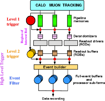
Data at the LHC are produced with the bunch crossing rate of 40 MHz. The ATLAS trigger (see Fig. 1) has the task to reduce this rate to an output rate of Hz after the Event Filter. The Level-1 trigger LVL1TDR reduces the initial 40 MHz to less than 75 kHz in less than 2.5 s, the maximum output rate and latency the trigger hardware can tolerate. In the HLT TP , where the boundary between the two trigger steps is purposefully kept flexible, the Level-2 trigger will reduce the rate to kHz and the Event Filter further to Hz. The available average latency of the two steps is substantially different, with 10 ms for the Level-2 trigger and 1 s for the Event Filter.
Central to the ATLAS trigger design is the Region-of-Interest (RoI) concept. The Level-1 trigger looks for regions of potentially interesting activity in the Calorimeters and the Muon Spectrometer that may correspond to candidates for high objects (electromagnetic, muon, tau/hadronic and jet clusters). The Level-2 trigger selection uses the RoI information (its type, position and the of the highest trigger threshold passed) of the Level-1 trigger as seeds for its processing. This strategy keeps the amount of raw data to be passed to the Level-2 trigger for processing at only a few per cent of the full event information.
While the raw data of the ATLAS subdetectors are held in readout buffers (ROB), the Level-2 trigger processes RoI information and raw data on a Level-2 Linux PC farm. On each node of the Level-2 farm, a Processing Application executes the Level-2 event selection software. Specialized, speed-optimized Level-2 trigger algorithms carry out the feature extraction in the region-of-interest indicated by the Level-1 trigger. While the Level-1 trigger does not combine the information from different subdetectors, the Level-2 trigger covers all subdetectors sequentially and gains additional information from combining their data.
Once an event has been accepted by the Level-2 trigger, the raw data of the full event are passed to the Event Builder, which in turn passes on the fully-built event to the Event Filter Linux PC farm. On the farm nodes, independent Processing Applications execute off-line-type selection algorithms that have access to the full event data, including the latest calibration and alignment information.
Though the type of selection algorithms used by the Level-2 trigger and the Event Filter are different, the software infrastructure that the algorithms use is kept as similar as possible between the two trigger levels. In order to achieve a high level of flexibility, it is desirable to retain to some degree the possibility to deploy an HLT algorithm either in the Level-2 trigger or in the Event Filter. This article describes the common software infrastructure that is used throughout the HLT. Given the much more stringent performance constraints of the Level-2 trigger, this approach meets limits that will be discussed as well.
III THE HIGH LEVEL TRIGGER EVENT SELECTION SOFTWARE
The HLT event selection software has four main components: the HLT algorithms that perform event reconstruction and feature extraction, the HLT Steering that calls a certain subset of the available HLT algorithms in a certain sequence depending on the types of RoI received from the Level-1 trigger, the HLT Data Manager that gives access to the information contained in the raw data, and the HLT raw Event Data Model that specifies the object representation of the raw data to be used by the HLT algorithms. This section describes how the four components work together and discusses the design and current implementation of the three components, HLT Steering, HLT Data Manager, HLT Event Data Model, that provide the infrastructure for the HLT algorithms both in the Level-2 trigger and in the Event Filter.
III.1 Working principle
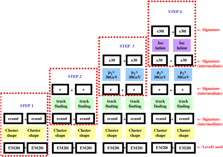
The following example illustrates the working principle of the HLT event selection software: The Level-1 trigger finds two isolated electromagnetic clusters with GeV each. This is a possible signature for the decay for which the ATLAS trigger accepts an event, if both electrons are isolated and have a minimum of 30 GeV.
The HLT validates this hypothesis in a step-by-step process. Intermediate signatures are produced as result of the algorithmic processing of a given step, and each intermediate signature is examined in order to be able to reject the hypothesis at the earliest possible moment. This procedure is managed by the HLT Steering package.
The validation procedure starts from the Level-1 RoI information as seed, as shown in Fig. 2. In this example, there are two isolated electromagnetic RoIs with GeV (“EM20i” in Fig. 2). The HLT Steering calls an HLT algorithm (“Cluster Shape”) to determine the cluster shape of the first seed. The cluster shape is found consistent with the electron hypothesis and the result is an electron candidate (“ecand”). The HLT Steering proceeds in the same way with the second seed and obtains a second electron candidate. These two electron candidates are considered as an intermediate signature (“ecand + ecand”). Since the event after this first step is still compatible with the signature, the HLT Steering starts the second step of the validation procedure. In this second step, the two electron candidates provide the seeds for the algorithmic processing. The HLT Steering calls a track finding HLT algorithm (“track finding”) for each of the two electron candidates. If for each of the electron candidates a track pointing to them is found, this second step results in two electrons that constitute another intermediate signature (“e + e”). Using, in the manner described above, the output of one step of the validation procedure as input to the next, the HLT Steering calls the appropriate HLT algorithms in the appropriate sequence to verify that the two electrons each have GeV and are both isolated. When finally, after the fourth step, the signature “e30i + e30i” has been reached, the ATLAS trigger accepts the event as a candidate for the decay with the desired electron characteristics.
To guarantee early rejection, the HLT Steering can reject an event after any step during the validation procedure. If the first step in the example above had not resulted in two electron candidates with the appropriate cluster shapes, the HLT Steering would have stopped the validation of the specific decay signature under scrutiny without passing to step 2. Note also that the HLT processing is not organized vertically (carry out the full sequence of algorithms to arrive first at a reconstructed electron for the first RoI and only then do the same for the second) but horizontally (carry out only the reconstruction foreseen in step x for the first and then the second seed and use the output as seeds for the next step).
III.2 Steering
In this section, the main ingredients of the HLT Steering package, Trigger Menus, Sequence Tables and Trigger Elements, are discussed briefly. For a detailed description, see Steering .
III.2.1 Trigger Menu and Sequence Table
In the example above, only one signature (hypothesis) and for this signature only one sequence of algorithms and intermediate signatures was considered. Different from this simple example, the ATLAS HLT accepts an event if it is consistent with at least one signature (hypothesis) in a whole catalog of possible ones. Also, depending on the Level-1 RoIs, there may be more than one possible sequence of algorithms and intermediate signatures per signature. But as in the example above, the HLT processing is organized horizontally, not vertically. This means also that the HLT does not examine one signature and only then the next. Instead, for each signature, the processing is broken up in single steps and the HLT Steering carries out the processing per step, not per signature.
Each step is accompanied by one Trigger Menu and one Sequence Table. A Trigger Menu is a list of all intermediate signatures in its step for which an event can be accepted. The Sequence Table specifies which HLT algorithms are to be executed, given the seeds as input to the step.
For more details, see TriggerMenu .
The HLT Steering deploys algorithms in a very specific way. The task of an HLT algorithm is not to perform a full scan for, e.g., all muon candidates in the event, independent of their location in the detector. Instead, the algorithm has to carry out a localized reconstruction, guided by a seed, limited to the area in the detector indicated by the seed. Hence, in the same event the HLT Steering calls the relevant algorithm once per seed, i.e. depending on the number of seeds possibly several times.
III.2.2 Trigger Elements
Communication between the HLT Steering and the HLT algorithms happens with the help of Trigger Elements. The HLT Steering hands over the seeds to a HLT algorithm by means of Trigger Elements. A HLT algorithm returns the result of its processing to the HLT Steering in the form of a Trigger Element.
A Trigger Element has a label, but does not hold any data content. It is related to Data Objects (RoIs, tracks, clusters, etc.) and other Trigger Elements in a navigable way. The signatures in a Trigger Menu consist of logical AND/OR combinations of Trigger Elements.
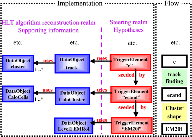
The following example (see Fig. 3), simplified as compared to the example in Fig. 2, illustrates how the HLT Steering uses Trigger Elements to communicate with HLT algorithms. The Level-1 trigger finds one isolated electromagnetic cluster with GeV. Assume for the sake of the argument that the ATLAS trigger accepts events with at least one isolated electron with 30 GeV. Then the RoI found by the Level-1 trigger is a possible signature for an event of this type.
In step 1, the electromagnetic RoI found by the Level-1 trigger is the seed for the HLT cluster shape algorithm. The HLT Steering creates a Trigger Element with label “EM20i” that has a navigable “uses” relationship to the Level-1 RoI as Data Object. The output of the HLT cluster shape algorithm is an electron candidate that the algorithm hands back to the HLT Steering as a new Trigger Element with label “ecand”. This Trigger Element has a navigable “uses” relationship to the calorimeter cluster that was the result of the algorithmic processing. Since the HLT cluster shape algorithm was seeded by the Level-1 RoI, its corresponding output Trigger Element, “ecand”, has a navigable “seeded by” relationship with its input Trigger Element, “EM20i”. Navigable “uses” relationships are also possible between Data Objects. This allows the HLT track finding algorithm in step 3 to access the calorimeter cluster on which its seed is based, and to access the calorimeter cells on which the calorimeter cluster is based. In addition, via the “seeded by” relationship between its input Trigger Element and the input Trigger Element of the preceding step, the algorithm has also access to the underlying Data Objects of that previous step.
In the design, the Trigger Elements represent the intermediate hypotheses that correspond to the intermediate signatures that the HLT Steering examines to decide whether to continue with the next step of the algorithmic processing. The Data Objects, on the other hand, represent the information supporting these hypotheses. Differentiating between Trigger Elements and Data Objects has the advantage of differentiating clearly between the HLT Steering realm, containing the hypotheses, and the HLT algorithm reconstruction realm, containing the supporting information.
III.3 Raw Event Data Model
Unlike the typical off-line situation where the data are stored in a convenient format, e.g. objects in a file or database, the HLT event selection software running on the HLT Linux farms can access data only in their raw format and needs to invoke the ATLAS Data Flow system DataFlow1 ; DataFlow2 ; DataFlow3 ; DataFlow4 in order to do so.
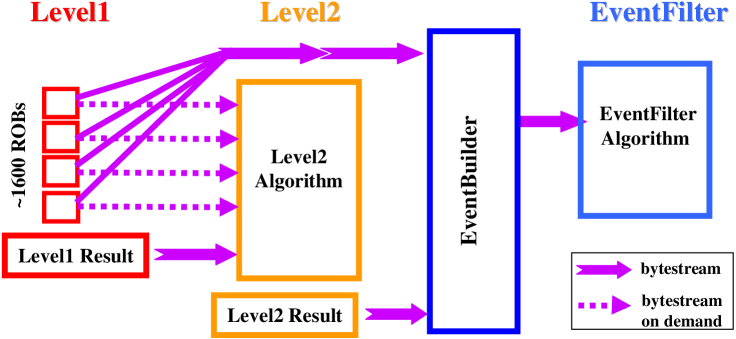
The Data Flow system transfers raw data to the HLT in bytestream format. Figure 4 illustrates where in the ATLAS trigger system raw data is exchanged via bytestreams. In the event of a positive Level-1 trigger decision, the Level-2 trigger receives the Level-1 trigger result, in particular the RoIs, by means of a bytestream. In addition, the Level-2 trigger can demand the bytestream fragment from any of the 1600 ROBs that each hold the raw data of a part of the ATLAS detector. When the Level-2 trigger accepts an event, the Event Builder receives the Level-2 trigger result and the bytestream from all 1600 ROBs and it passes the fully-built event by way of another bytestream to the Event Filter.
III.3.1 Raw Data Objects and Detector Elements
In order to allow the HLT algorithms access to the raw data information in these bytestreams, this information has to be represented in object form, as Raw Data Objects (RDOs). The HLT algorithms access the raw data information by means of the RDOs and the transient event store, where the RDOs are stored.
The Raw Event Data Model (Raw EDM) is part of the HLT EDM and specifies the design of the RDOs for each ATLAS subdetector and each bytestream in the Data Flow system. The Raw EDM has to map onto one another data of very different granularity. The Data Flow system provides data with a minimum granularity of one ROB, while a HLT algorithm typically needs data organized by geometric detector unit.
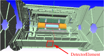
For example, in the ATLAS Muon Spectrometer, a geometric detector unit of interest for a HLT selection algorithm is a chamber. A chamber is a physical unit, for example of Monitored Drift Tubes (MDT), that share the same physical support structure, are installed as a whole and may be described by a single set of condition (e.g. alignment, etc.) constants. The Raw EDM specifies for all ATLAS subdetectors the object representation of the relevant geometric detector units, the Detector Elements (see Fig. 5).
In the case of the MDT chambers of the Muon Spectrometer, the Detector Element corresponds to a chamber. In the same way as a chamber can be viewed as a collection of readout channels, a Detector Element object is a collection of RDO objects which each hold the information of one readout channel.
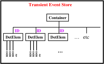
RDOs are stored in the transient event store ordered according to Detector Elements. The transient store contains for each subdetector a container of Detector Elements (see Fig. 6). Each Detector Element has a unique identifier ID by which it can be retrieved from the store, thus allowing with one request to the transient store to retrieve collections of RDOs, which respresent collections of readout channels in geometric detector units.
III.4 Bytestream converters
The raw data in the bytestream format in which they are held by the ROBs can be viewed as a representation of the raw data information in an event. The RDOs, organized by Detector Element, are another representation of this information. The conversion from bytestream representation to RDO representation is the task of Bytestream Converters. They carry out the conversion on demand of an HLT algorithm. Their implementation consists of a general infrastructure part that uses subdetector specific methods for decoding the information from bytestream format to RDO format. The general part is, for example, responsible for storing the RDOs in the correct Detector Element order in the transient store.
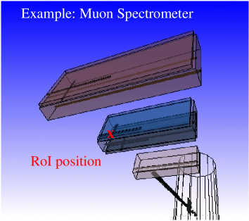
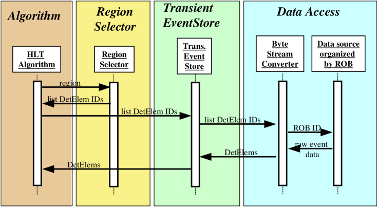
Raw data access via Bytestream Converters proceeds in the following way (see Fig. 7). The HLT Steering calls an HLT algorithm by passing to it a Trigger Element with a navigable link to a RoI Data Object that contains the RoI position. This RoI can, for example, be located in the Muon Spectrometer. The HLT algorithm typically needs access only to the raw data in those Muon Spectrometer chambers within a certain region around the RoI position (see Fig. 8). These chambers correspond to a certain set of Detector Elements. The task of identifying this set of Detector Elements, given a region in the pseudorapidity and the polar angle , is performed by the Region Selector RegionSelector . The Region Selector returns to the calling HLT algorithm the list of identifiers of the appropriate set of Detector Elements. The HLT algorithm requests the Detector Elements from the transient store with the help of this identifier list.
At this stage, two situations can occur. If the requested Detector Elements are already available in the transient store, the store simply returns them. If they are not available, however, the corresponding raw data information first has to be requested from the Data Flow system. In this case, the transient event store invokes the correct Bytestream Converter, which in turn requests the raw data in bytestream format from the appropriate ROBs. From the succession of 32-bit words sent by each ROB, the Bytestream Converter extracts the relevant information and uses it to initialize the collections of RDOs. The thus obtained collections of RDOs, or Detetcor Elements, are stored in the transient store, which passes them on to the HLT algorithm.
The extraction of raw data information into RDOs can be supplemented by additional data preparation algorithms, e.g. cluster finders for the Silicon Trackers. The object representation of extracted and prepared raw data are called Reconstruction Input Objects. Their definition is part of the HLT EDM. They are organized inside the transient store in collections as are RDOs, and can be requested by an HLT algorithm in the same way as RDOs.
IV OFF-LINE CODE IN ON-LINE CONTEXT
A high level of integration of the code designed for off-line use and the code designed for on-line use is clearly a desirable design goal. Ideally, it should be possible to develop and maintain on-line software on simulated and real data in a well-tested, flexible and user-friendly environment as is offered by the off-line software. This does not only apply to the HLT algorithms, but also to the HLT infrastructure code used by them. Furthermore, it clearly enhances the HLT flexibility in dealing with changes in the LHC running conditions when it is possible to migrate software freely between off-line environment and Event Filter and between Event Filter and Level-2 trigger.
In the previous sections, the common software infrastructure of Level-2 trigger software and Event Filter software has been described. In order to use this HLT software infrastructure and the HLT algorithms in an off-line environment, the HLT software has to comply with the basic design principles of the ATLAS off-line framework.
The ATLAS off-line framework, Athena Athena , is based on a GAUDI GAUDI (developed by the LHCb experiment) core. As a consequence, Athena has adopted a number of the basic principles of the GAUDI design. Examples are the separation of the data from the algorithms producing and consuming the data, separation of the transient and the persistent representation of data and the use of converters that convert one data representation into another.
For the HLT event selection software this means, for example, that HLT algorithms are forced to communicate indirectly, via the transient event store. This requirement is met by the use of Trigger Elements, as described in Sec. III.2.2. It also means that persistent data can be made available to the HLT event selection software only by means of converters that convert them into a transient representation that is then stored in the transient event store, from where HLT algorithms can request data. The Bytestream Converters discussed in Sec. III.4 and their use as illustrated in Fig. 7 comply with this requirement. Furthermore, using the HLT event selection software in Athena implies at the very least common interfaces to general services, and may even mean using the very same services, e.g. database access tools, geometry service etc., by Athena and by the on-line framework.
The HLT event selection software also needs to comply with the much more stringent on-line performance requirements concerning speed and robustness. Hence, also any off-line-imposed elements or code elements imported from the off-line environment must meet the on-line performance requirements. They are considerably more stringent than would be otherwise needed for pure off-line use.
The following section describes the current off-line dependencies introduced into the HLT software for the above mentioned reasons. The experience gained so far in the attempt of using off-line code in the on-line context of the trigger is discussed.
IV.1 Current Off-Line Dependencies
A high level of integration between off-line and on-line code can be achieved in different ways. One possibility consists in choosing the interfaces in the off-line and in the on-line code such that on-line software can be used in the off-line framework and vice versa. Another possibility is to use the same framework for off-line and on-line purposes. In the concrete ATLAS situation, this means using Athena as on-line framework as well. In addition, any combination of these two extremes is possible.
In the current implementation of the HLT software, Athena is used as framework in the Event Filter. Level-2 employs a specialized framework that uses interfaces compatible with those in Athena, so that any Level-2 infrastructure and algorithm code can also be used within Athena (see next section). The HLT infrastructure code (e.g. transient event store, Bytestream Converters, etc.) currently re-uses code developed in Athena.
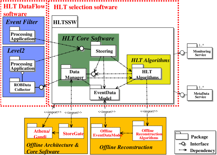
Figure 9 depicts the current off-line dependencies in the HLT event selection software. The HLT framework depends on the off-line framework. For the Event Filter this means re-use of Athena as framework, for the Level-2 trigger this means use of a slightly modified version (see next section) of the Athena core software, based on GAUDI. The Data Manager in the current implementation is the off-line transient event store, StoreGate StoreGate . The HLT EDM re-uses the off-line EDM. In the Event Filter, off-line algorithms are re-used as selection algorithms. In the Level-2 trigger, specialized Level-2 algorithms are employed which, however, are set up such that they can also be run in the Athena framework.
The execution of the HLT event selection software is controlled by a Processing Application that is part of the HLT Data Flow and Data Acquisition software.
IV.2 The Special Level-2 Environment
The performance constraints imposed by the HLT are most stringent for the Level-2 trigger. There, the average latency available to the HLT selection software for accepting or rejecting an event is 10 ms. The Level-2 software needs to be able to handle a data input rate of up to 75 kHz and to sustain a data output rate of kHz error-free and deadtime-free for extended periods of time. Requirements of such stringency with respect to speed and robustness are usually not met by software designed for pure off-line use. An additional complication arises from the need for multi-threading in the Level-2 trigger.

In order to keep the idle time of the CPUs in the Level-2 Linux PC farm to a minimum, each CPU processes in parallel three different events, i.e. each Level-2 CPU carries out at the same time three execute loops. This is in marked difference to the situation foreseen in Athena, where the initialization phase is followed by a single execute loop that ends in a finalization phase (see Fig. 10). In the case of running inside Athena, Athena controls the event execute loop; in the multi-threaded Level-2 software the control needs to be with the HLT Data Flow software. In addition, in the Level-2 software, all algorithms and services have to be configured and initialized strictly outside of the event execute loop. Hence Athena cannot be used as HLT framework for the Level-2 trigger.
In order to comply nonetheless with the design goal that the Level-2 event selection software be usable with the Athena framework for development and maintenance purposes, an interface layer between the HLT selection and the HLT Data Flow software was implemented, the so-called Steering Controller GAUDIL2 . The Steering Controller uses only a minimal set of GAUDI features. In addition, it uses a modification to the GAUDI base libraries that allows thread-specific instantiation. The standard GAUDI command is, for example, replaced by , where corresponds to the number of the thread (1, 2, 3). Accordingly, GAUDI services are called with the command and algorithms with , etc. The possibility of thread-specific instantiation has since been included in GAUDI as a standard feature. The Steering Controller can be used within the off-line framework Athena because in a single-thread environment the suffix collapses to a blank. Beyond this the Steering Controller uses only standard GAUDI features, which are all contained in the GAUDI-based Athena.
The special Level-2 feature of running in multi-thread mode may cause problems when using standard software tools as, e.g., the Standard Template Library (STL), even when the software components used are in principle thread-safe. An unexpected problem of this kind arose with the specific implementation of STL containers in use in the HLT code. The container implementation, though thread-safe, proved highly thread-inefficient by setting unnecessary locks. The problem was overcome by modifying by hand the container allocator implementation MultiThreading .
It should be noted that the problems arising from the use of multiple threads in the Level-2 trigger software are not present for the Event Filter. The Event Filter uses multiple threads, but the Data Flow and HLT event selection software are set up in a different way. As a result, it is possible to use Athena as is as the framework for running HLT selection algorithms in the Event Filter AthenaEF . However, when Athena was used for the first time in the Event Filter, it became aparent that an inacceptable 30% of the total processing time per event was spent in the off-line Raw EDM available at that time. This problem has since been remedied, but illustrates the need for a thorough evaluation of the suitability of off-line code for use in the HLT software. It also illustrates the need for a close and continuous collaboration between the HLT (“on-line”) and the “off-line” communities in order to adopt successfully “off-line” software for “on-line” use.
V CONCLUSIONS AND OUTLOOK
The architecture of the HLT selection software described in this article is currently being validated by implementing the software for full vertical trigger slices. Two vertical slices are currently under development, an electron/gamma slice and a muon slice. The vertical trigger slices comprise the software to simulate the full chain of trigger decisions, starting with the Level-1 trigger, that leads to identifying an event as containing a single electron, gamma or muon. Integration of the HLT selection software with the other components of the HLT software is on-going with the goal of running the electron/gamma and muon vertical slices in testbeds of the foreseen Linux PC farms. Detailed measurements of timing and physics performance of each part of the HLT software are under way and will be reported in the HLT Technical Design Report in summer 2003.
A central goal of the current implementation of the HLT selection software is a high level of integration between off-line and on-line code. This goal has sparked off a very fruitful collaboration between the HLT and the on-line software developer communities. The attempt of adapting and re-using off-line code in the HLT software has been carried furthest in the specific way of accessing raw data in the HLT by means of Bytestream Converters that are hidden behind a call to the off-line transient event store, StoreGate.
Given the ever increasing available CPU speed, allowing an ever higher level of abstraction, the concept of re-using off-line code in the on-line context appears a logical development. However, given the stringent constraints and performance requirements of the HLT, the present implementation of the HLT selection software and the heavy re-use it makes of off-line software is clearly experimental. This is in particular true for the Level-2 trigger. The results of the on-going validation effort will show if the chosen ansatz is sustainable.
VI ACKNOWLEDGMENT
We would like to acknowledge the help and support of the ATLAS Data Acquisition Group and the ATLAS Off-Line and Detector software groups.
References
- (1) ATLAS collab, “ATLAS Level-1 Trigger: Technical Design Report”, CERN-LHCC-98-014, ATLAS-TDR-12, June 1998.
-
(2)
ATLAS collab., “ATLAS High-Level Triggers, DAQ and DCS: Technical Proposal”,
CERN-LHCC-2000-017, March 2000;
ATLAS collab., “ATLAS High-Level Triggers, DAQ and DCS: Technical Design Report”, in preparation. - (3) G.Commune, “The Algorithm Steering and Trigger Decision mechanism of the ATLAS High Level Trigger”, these proc.
- (4) M.Elsing, “Configuration of event-selection criteria in the ATLAS trigger system”, these proc.
- (5) G.Lehmann, “The DataFlow system of the ATLAS Trigger and DAQ”, these proc.
- (6) S.Stancu, “The use of Ethernet in the DataFlow of the ATLAS Trigger and DAQ”, these proc.
- (7) S.Wheeler, “Supervision of the ATLAS High Level Trigger System”, these proc.
- (8) S.Kolos, “On-Line Monitoring software framework in the ATLAS experiment”, these proc.
- (9) R.D.Schaffer, “Use of a generic identification scheme connecting events and detector description in the ATLAS experiment”, these proc.
- (10) V.Boisvert, “The Region of Interest Strategy for the ATLAS Second Level Trigger”, these proc.
-
(11)
A.Bazan et al., “The Athena Data Dictionary and Description Language”,
these proc.;
V.Fine, H.Ma, “Root Based Persistency in Athena (ATLAS)”, these proc. - (12) P.Mato (ed.), “GAUDI - Architecture design document”, LHCb-98-064 COMP, Nov 1998.
- (13) P.Calafiura, “The StoreGate: a Data Model for the ATLAS Software Architecture”, these proc.
- (14) S. Gonzalez et al., “Use of Gaudi in the LVL2 Trigger: The Steering Controller”, ATL-DAQ-2002-012, Jun 2002.
- (15) S.Gadomski, “Experience with multi-threaded C++ applications in the ATLAS DAQ system”, these proc.
- (16) C.Bee et al., “HLT Validation of Athena”, ATL-DAQ-2002-005, Jan 2002.