IMPEDANCES OF TEVATRON SEPARATORS
Abstract
The impedances of the Tevatron separators are revisited and are found
to be negligibly small in the few hundred MHz region,
except for resonances at 22.5 MHz. The latter
are contributions from the power cables which may drive head-tail instabilities
if the bunch is long enough.
1 I. INTRODUCTION
Large chromaticities ( units) were required to control the vertical transverse head-tail instabilities observed recently in the Tevatron. Application of the head-tail growth expression [1] reveals that the necessary transverse impedance to drive such instabilities has to be at least twice the amount estimated in the Run II Handbook. [2] This underestimation becomes thrice when it was suggested [3] that the transverse impedance of the Lambertson magnets have been overestimated by ten fold.111 The Run II Handbook estimate has been rather rough, but reasonable. The C0 Lambertson magnet removed recently shows very large transverse impedance. It was further suggested that most of the transverse impedance actually comes from the static separators: the vertical transverse impedance should be 5.33 M/m assuming 27 separators while the Run II Handbook estimate has been only 0.082 M/m assuming 11 separators.222 0.82 M/m quoted in the Run II Handbook is a misprint. This 26-time difference for each separator prompts us to review the impedances in detail by numerical computation, theoretical reasoning, and experimental measurement. The conclusion points to the fact that the separators actually contribute negligibly when compared with other discontinuities in the Tevatron vacuum chamber, except for the rather large resonances at 22.5 MHz due to the power cables.
2 II. NUMERICAL COMPUTATIONS
We model a separator without the power cables as two plates 6 cm thick, 20 cm wide, 2.57 m long, separated by 5 cm inside a circular chamber of length 2.75 m and radius 18 cm (Fig. 2). The beam pipe is circular in cross section with radius 4 cm. The 3-D code MAFIA in the time domain [4] has been used to obtain the longitudinal and transverse impedances shown in Fig. 2. We find that, at low frequencies, the longitudinal impedance per harmonic and the vertical transverse impedance are, respectively, and /m, which agree with the estimates given in the Run II Handbook.


In many cases, a 2-D approximation, assuming cylindrical symmetry of the 3-D problem, should give us a good insight as to the physics of the problem. The advantage is obvious; we can use more mesh points to better represent the geometry. The first 50 resonant modes computed by the 2-D URMEL code [4] are shown in Fig. 3 (top). They are well below the cutoff frequency of 4.59 GHz and therefore appear as narrow resonances.


The separator can be viewed as two pill-box cavities joined by a coaxial waveguide. The coaxial waveguide resonates when its length equals to an integral number of half wavelengths. Thus, the lowest mode has a frequency of MHz and successive modes are separated also by 54.5 MHz, where is the velocity of light and m is the length of separator. To excite these standing TEM modes in the coaxial waveguide, electromagnetic fields must penetrate into the separator, and penetration is only efficient when the frequency is near the resonant frequencies of the cavities at each end of the separator. These pill-box-like cavities have a radial depth of cm with the first resonance at MHz, and we do see coaxial-guide modes excited very much stronger near this frequency. The next pill-box-cavity mode is at 1463 MHz with a radial node at cm which is very near the outer radius of 8.5 cm of the cylindrical plates. Thus a rather pure cavity mode is excited with very little contamination from the coaxial guide. This explains why we see a very strong excitation of this mode without many coaxial-guide modes at nearby frequencies. The third pill-box-cavity mode at 2294 MHz can also be seen in the figure with coaxial-guide modes at surrounding frequencies. Because excitation decreases with frequency, the shunt impedances are much smaller.
Due to the finite mesh size and rms bunch length used in the computation, MAFIA broadens all these sharp resonances. If all quality factors are broadened to , the results look very similar to those in Fig. 2, implying that our interpretation of the longitudinal impedance of the separator is correct.
Similar analysis applies to the transverse dipole modes. The lowest 50 resonances computed by URMEL are shown in Fig. 3 (bottom). The first two transverse resonances in the pill-box cavities are 1016, 1860 MHz. We do see coaxial-guide modes enhanced near these frequencies. There is a special mode when one wavelength of the magnetic field wraps around the “cylindrical plate” between the plate and the encasing outer shield. The radius is from to 18 cm. The wavelength will be and the frequency will be between 265 and 562 MHz. This explains the cluster of low-frequency coaxial-guide modes in the URMEL results. There is no cylindrical symmetry in the actual separator and this low-frequency cluster is therefore not present in the MAFIA results. Again if we broaden the sharp resonances until the quality factor reaches 15, the real and imaginary parts of the transverse impedance will look similar to the MAFIA results of Fig. 2.
3 III. COMPARISON WITH BPM
Although the Tevatron stripline beam-position monitor (BPM) is similar in structure to the separator, however, its impedance is completely different. Here, the striplines play the role of the separator plates. The main difference is that each end of the striplines is terminated with a resistor of , which is equal to the characteristic impedance of the transmission line formed from the stripline and the enclosing outer shield. As a pulse of protons crosses the upstream gap, it creates on the beam-side of the stripline negative image charges, which move forward with the beam pulse. Since the stripline is neutral, positive charges will be created at the underside of the stripline. These positive charges, seeing a termination in parallel with a transmission line of characteristic impedance , split into two equal halves: one half flows down the termination while the other half travels along the transmission line and flows down the termination at the other end of the stripline. When the beam pulse crosses the downstream gap of the BPM, the negative image charges on the beam-side of the stripline wrap into the underside of the stripline; one half flows down the downstream termination while the other half flows backward along the transmission line and eventually down the upstream termination. Assuming the transmission line velocity to be the same as the beam velocity, the current in the downstream termination vanishes between one half of the stripline underside positive charges and one half of the wrap-around negative image charges. At the upstream termination, we see first a positive signal followed by a negative signal delayed by twice the transit time of traveling along the stripline. Thus the potential across the upstream gap is
| (1) |
where is the length of the stripline and is the beam current. The factor occurs because only one half of the current flows down the upstream termination each time. The impedance of one stripline in the BPM becomes
| (2) |
where is the angle the stripline subtends at the beam pipe axis. The added factor, , indicates that only a fraction of the image current flows across the gap into the stripline and only this fraction sees a gap potential.
For a separator plate, there are no terminations on either end. As a result, while the negative image charges flow along the beam-side of the plate, all the positive charges needed to balance the neutrality of the plate flow along the underside of the plate. These negative and positive charges just annihilate each other when the beam pulse reaches the downstream end of the plate. Thus there is no dissipation if the plates are considered perfectly conducting. Therefore, the impedance in Eq. (2) does not apply. The only contribution to the impedance come from the resonances in the cavity gaps. Since these resonant frequencies are high, there is little contribution in the few hundred MHz range.
4 IV. MEASUREMENT
The coupling impedances of a separator have recently been measured [5] via the attenuation by stretching a tin-plated copper wire through the separator for the longitudinal mode and two wires for the transverse mode. The impedances are derived from
| (3) |
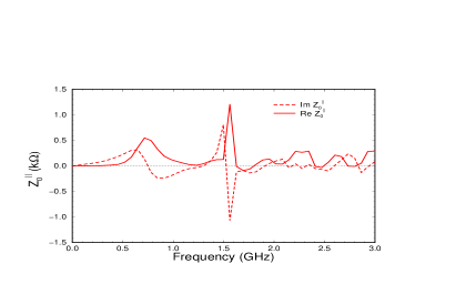
where cm is the separation of the two wires and is the characteristic impedance of the cables connected to the network analyzer, to which the wires have been matched. In Fig. 4, we plot333 If we plot instead of , the 22.5 MHz resonant peak will not be visible. the measured and .


We see that both and contain the resonant structures determined by MAFIA and are small in the few hundred MHz region. However, we do see a large resonance at 22.5 MHz, which can be traced to coaxial power cables attached about from one end of the plate through a resistor. Typically, the cables are two-meter long and terminate into a 1 M impedance. These cables extend the electric lengths of the plates and the first waveguide mode is shifted from 54.5 MHz to 22.5 MHz. The function of the series resistor is to remove any sparks if present. Actually, this resistor, being situated near the end of a plate, absorbs the oscillatory current of this resonant mode. Without this resistor, the 22.5-MHz peak in both and will be almost tripled. On the other hand, these peaks will disappear if the power cables are removed. There are 24 separators, giving in total and M/m, which are rather large. The longest Tevatron bunch has been cm rms. Considering , the lowest head-tail mode will have a frequency of MHz. Thus this 22.5 MHz mode may pose a danger. There are ways to alleviate the effect. One is to increase the length of the power cables so as to further reduce the resonant frequency. A second way is to increase the damping resistors to about , [5] hoping that the peak impedances will be damped by a factor of ten. The designed Tevatron rms bunch length is only cm. If this shorter bunch length can be achieved, the lowest head-tail mode will have a frequency of 82.8 MHz, too high to be affected by the power cables.
5 V. OTHER ESTIMATION
Ref. [3] suggests the vertical transverse separator wake,
| (4) |
based on two plates separated by cm without any outer shield, where is the free-space impedance. The vertical transverse impedance is
| (5) |
and becomes, at low frequencies,
| (6) |
which gives the large estimate cited earlier in the Introduction. The wake resembles the stripline BPM wake [cf Eq. (1)] with a reflected current at the downstream end of the separator plate. As we have discussed earlier, there is no reflected current because the positive and negative charges created on the plate annihilate when the beam pulse crosses the downstream separator gap. An outer shield is very essential for a separator model, because a waveguide/transmission line will be formed. For the BPM, the transmission line characteristic impedance enters into the impedance expression of Eq. (2). Without the transmission line, here in Eq. (6), the much larger free-space impedance enters instead.
References
- [1] A.W. Chao, Physics of Collective Beam Instabilities in High Energy Accelerators, Wiley, 1993, Section 6.3.
- [2] Run II Handbook, Beams Division, Fermilab, Section 6.7; see web address: http://www-bd.fnal.gov/lug/ runII_handbook/RunII_index.html; King-Yuen Ng, Impedances and Collective Instabilities of the Tevatron at Run II, Fermilab TM-2055, 1998.
- [3] Alexey Burov and Valeri Lebedev, Head-Tail Instability in the Tevatron, talk given at Fermilab on November 14, 2002.
- [4] MAFIA User Guide, DESY, LANL and KFA, May 3, 1988; URMEL and URMEL-T User Guide, DESY M-17-03, 1987.
- [5] James L. Crisp and Brian J. Fellenz, Measured Longitudinal Beam Impedance of a Tevatron Separator, Fermilab TM-2194, 2003; Tevatron Separator Beam Impedance, Fermilab TM-2202, 2003.