Configuration of the ATLAS Trigger System
Abstract
In this paper a conceptual overview is given of the software foreseen to configure the ATLAS trigger system. Two functional software prototypes have been developed to configure the ATLAS Level-1 emulation and the High-Level Trigger software. Emphasis has been put so far on following a consistent approach between the two trigger systems and on addressing their requirements, taking into account the specific use-case of the ‘Region-of-Interest’ mechanism for the ATLAS Level-2 trigger. In the future the configuration of the two systems will be combined to ensure a consistent selection configuration for the entire ATLAS trigger system.
I INTRODUCTION
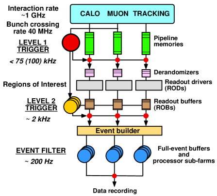
The Large Hadron Collider (LHC), which is currently being built at the European Organization for Nuclear Research (CERN) in Geneva, will collide proton beams at a centre-of-mass energy of 14 TeV and with a bunch-crossing rate of nominally 40 MHz. At the design luminosity of an average of about 25 proton proton interactions will take place in each of the bunch-crossings. An efficient and selective trigger system is needed to reduce the amount of data that will arise from these conditions and to select the relevant physics events from the background of soft interactions. The trigger of the ATLAS experiment atlas is designed as a multi level system that reduces the event rate from 40 MHz to about 200 Hz at which events (that will have an average size of about 1.6 MB) can be written to mass storage. Fig. 1 gives an overview of the trigger system which is divided in three levels (from top to bottom in Fig. 1) :
-
•
The Level-1 (LVL1) trigger is a hardware-based system that receives signals from the calorimeter and muon detectors of ATLAS. Its task is to reduce the event rate to 75 kHz within a latency of 2.5 s. During that time the data from all detectors are stored in pipelined memories. LVL1-accepted events are transfered to the Read-Out Buffers.
-
•
The Level-2 (LVL2) trigger, which forms part of the High-Level Trigger (HLT), is based on software selection algorithms running in processor farms. LVL2 can access data from all sub-detectors of ATLAS in so called ‘Regions-of-Interest’ that were identified by the LVL1 system. The average time budget of LVL2 is about 10 ms, hence a fast rejection strategy is needed using specialized trigger algorithms.
-
•
The Event Filter (EF) is also based on software selection algorithms. In contrast to LVL2 it runs after the event building, such that the complete event information is available to the EF algorithms. In the EF, a thorough event selection and classification process will be performed within a time budget of a few seconds. The EF algorithms are foreseen to be based on offline reconstruction code using the full calibration and alignment information. Events accepted by the EF are written to mass storage.
In this paper, the concepts and mechanisms that are foreseen for configuring the ATLAS trigger selection are discussed. The task comprises the definition of so called ‘trigger menus’ (i.e., the definitions of the physics signatures the experiment should be triggered on), the set-up of the selection software for the HLT as well as the set-up of the LVL1 trigger hardware. Currently the latter part of the configuration is implemented only in a functional prototype of the LVL1 emulation software.
II LVL1 TRIGGER CONFIGURATION
II.1 A short Overview of the LVL1 Trigger
The LVL1 trigger lvl1cite is a complex hardware system consisting of a calorimeter trigger, a muon trigger and the central trigger processor (CTP). An overview of the LVL1 system222Note that the Region-of-Interest Builder (RoIB) is formally not a LVL1 sub-system. is given in Fig. 2.
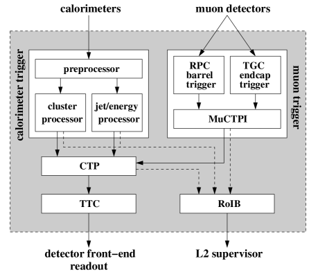
The calorimeter trigger receives as inputs 7̃200 analogue signals from a dedicated trigger-tower electronics that locally combines information from calorimeter cells in the various ATLAS calorimeters. A trigger tower has a typical granularity of .
The task of the calorimeter trigger is to search for localized energy depositions that are a signals for high transverse energy electrons/photons, particles, hadrons or jets. The energy depositions are compared to a set of programmed transverse-energy thresholds and the multiplicity of objects passing each of the thresholds is counted. There are thresholds for electrons/photons, for leptons or hadrons, eight for central jets, and four for forward jets. In addition, the calorimeter trigger provides global energy sums to measure the total and missing transverse energy in an event. These sums are discriminated against eight thresholds for missing transverse energy and four for total transverse energy.
The multiplicity for each threshold is sent to the CTP. In addition the type, position and threshold information about each candidate object is recorded in so called ‘Regions-of-Interest’ (RoIs). For selected events, these RoIs are sent to the HLT via the Region-of-Interest Builder (RoIB) in order to seed the LVL2 selection.
In analogy, the muon trigger, which is based on information from dedicated fast muon chambers, derives the multiplicity count for muon candidates passing six programmable thresholds. The multiplicities are again sent to the CTP, and the information on the candidates or RoIs is sent to the HLT.
The CTP receives all the multiplicity and energy-sum-threshold information from the calorimeter and muon triggers. It combines them according to the trigger menu to derive the LVL1 event decision. The CTP provides information to the HLT for selected events indicating which signatures were fulfilled.
II.2 Configuration of the LVL1 Trigger
For the final system the task of the LVL1 configuration will be the preparation of the LVL1 hardware for data taking. Up to now only preliminary ideas exist on how to configure consistently the LVL1 sub-system hardware, the calorimeter and muon triggers and the CTP. Questions being addressed in this context range from storage of hardware configuration files, through keeping track of configuration changes, to checks for consistency and hardware compliance. These issues will not be touched upon in this article. However, the configuration of the LVL1 has a purely algorithmic aspect that defines the physics selection strategy. This part of the configuration, which is implemented in the LVL1 software prototype and is part of the ATLAS simulation chain, is described here.
The first task of the LVL1 configuration code is to translate the trigger menu, i.e. the collection of physics signatures LVL1 is supposed to trigger on, into something that the emulation of the CTP can understand and use in making the event decision based on the calorimeter and muon trigger inputs. A physics signature, a so called ‘trigger item’, is a logical combination of requirements formulated as ‘trigger conditions’ in terms of multiplicities of candidate objects delivered by the calorimeter and muon triggers. Such candidates are typically high- objects in the events that are a signature for interesting physics events. A simple example of a trigger item is:
electron/photon candidate with 10 GeV
and
muon candidate with 15 GeV
or, in the ATLAS LVL1 notation:
1EM10+1MU15
which combines two trigger conditions ‘1EM10’ and ‘1MU15’. In this notation the string ‘EM’ represents a candidate of type electron/photon and the integer numbers before and after the string symbolize the required multiplicity and transverse energy/momentum, respectively. The combination of a candidate string and a threshold value like ‘EM10’ is called a ‘trigger threshold’. The ATLAS LVL1 system distinguishes electron/photon (‘EM’), muon (‘MU’), tau/hadrons (‘HA’), (forward) jets (‘JT’, ‘FR’, ‘FL’), total and missing transverse energy (‘ET’, ‘TM’), and the transverse energy calculated as the sum of all jet transverse energies (‘SM’).
The second task of the configuration code is to set up the the calorimeter and muon trigger sub-systems such that they deliver the information required by the CTP in order to derive the event decision based on the trigger menu. The LVL1 sub-detector simulation has to be configured so that each sub-system delivers the multiplicities for the correct set of trigger thresholds. For the above example, the calorimeter trigger has to be configured such that it delivers to the CTP the multiplicity count for the threshold ‘EM10’, i.e. the number of electron/photon candidates with transverse energy above 10 GeV. It is obvious that the trigger menu and the trigger thresholds for the calorimeter and muon triggers have to be defined consistently. In particular, all thresholds used in the definition of any trigger condition in any trigger item must be delivered by the calorimeter and muon trigger simulations and thus need to be configured.
In the configuration process for the CTP simulation the restrictions imposed by limited abilities and resources of the real hardware have to be taken into account.
The LVL1 trigger configuration software is currently being adapted to configure as well the LVL1 trigger hardware by deriving the necessary look-up table and FPGA configuration files from the trigger menu and trigger threshold list. Such a common configuration scheme will allow for cross-checks between hardware and software.
II.3 XML Definition of Trigger Thresholds
To configure LVL1 the trigger menu and the list of thresholds are defined using XML and are parsed into instances of C++ classes using the Xerces DOM API xerces . The chosen notation exploits the facility of XML to define logical structures by introducing user-defined tags. The tag structure used for the ‘trigger thresholds’ is:
<TriggerThresholdList>
   <TriggerThreshold name="..." type="...">
      <TriggerThresholdValue thresholdval="..." />
   </TriggerThreshold>
</TriggerThresholdList>
It is important to note that a trigger threshold contains one or more ‘trigger threshold values’. This concept allows to assign different threshold values (in GeV) to various topological regions of the detector using attributes that set limits to the validity in terms of and in ATLAS. This concept is foreseen for the calorimeter trigger hardware and is subject to current detailed studies. The previous example using a set of trigger threshold values may look like:
<TriggerThresholdList>
   <TriggerThreshold name="..." type="...">
      <TriggerThresholdValue
          thresholdval="5" etamin="-2" etamax="0" />
      <TriggerThresholdValue
          thresholdval="10" etamin="-5" etamax="-2" />
      <TriggerThresholdValue
          thresholdval="5"  etamin="0" etamax="2" />
      <TriggerThresholdValue
          thresholdval="10" etamin="2" etamax="5" />
   </TriggerThreshold>
</TriggerThresholdList>
The TriggerThreshold tag has several attributes, the most important ones are ‘name’ and ‘type’:
-
•
The ‘name’ attribute assigns a unique label to the trigger threshold. It is needed to connect the threshold to the trigger condition. An example for a ‘name’ is ‘EM10’.
-
•
The ‘type’ attribute is required mainly for technical reasons: The number of the different thresholds is limited - for example only up 6 muon thresholds can be implemented because of hardware limitations. The ‘type’ attribute helps in this book-keeping.
When the XML tags are parsed, the attributes are translated into data members of the corresponding C++ class instance.
When the XML tags are parsed, the attributes of the TriggerThresholdValue tags are translated into data members of the corresponding C++ objects. Depending on the ‘type’ attribute of the TriggerThreshold tag, different attributes for the TriggerThresholdValue tags are expected (e.g., definition of isolation criteria). Only the ‘thresholdval’ attribute is common, which is used to define the threshold value (in GeV).
II.4 XML Definition of the Trigger Menu
The XML definition of the trigger menu uses the TriggerMenu, TriggerItem and TriggerCondition tags. The basic structure of the XML file for the trigger menu is the following:
<TriggerMenu>
   <TriggerItem>
      <TriggerCondition threshold="..." mult="..."/>
   </TriggerItem>
</TriggerMenu>
In addition the special tags AND, OR and NOT are available to allow for logical combinations of trigger conditions for a given the trigger item, for example:
<TriggerMenu ...>
   <TriggerItem ...>
      <AND>
         <TriggerCondition ... />
         <OR>
            <TriggerCondition ... />
            <NOT>
               <TriggerCondition ... />
            </NOT>
         </OR>
      </AND>
   </TriggerItem>
</TriggerMenu>
The TriggerMenu tag has as only attribute ‘TM_ID’ to set a label for the trigger menu. The TriggerItem has different attributes: ‘TI_ID’ is used to set a name; ‘mask’ indicates via values ‘on’ or ‘off’ whether or not the item is to be used in the LVL1 decision; ‘priority’ is set to ‘low’ or ‘high’, depending on whether or not the item should have priority in the CTP dead-time algorithm; ‘prescale’ is an integer indicating the prescale factor to be used in the CTP simulation. The TriggerCondition tag has two attributes: ‘threshold’ to give it a label and a ‘mult’ to specify the required mulitplicity for this trigger condition. The ‘threshold’ attribute has to be the same as the ‘name’ attribute of a corresponding TriggerThreshold tag. An example of the logical structure of the XML tree of the trigger menu is shown in Fig. 3.

II.5 Implementation of the LVL1 Configuration
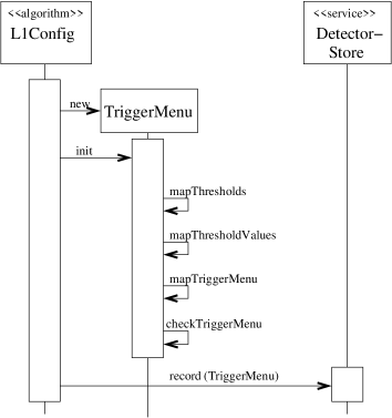
Fig. 4 shows a sequence diagram of the configuration process. L1Config is the name of the algorithm in the ATLAS offline framework Athena, in which the HLT trigger configuration is implemented. The central class of the configuration is the so-called TriggerMenu. A single instance is created by the L1Config algorithm, that also calls the TriggerMenu::init method. The TriggerMenu contains or has access to all the information in the two XML files for the trigger menu and the trigger thresholds.
The LVL1 trigger menu basically is a collection of trigger items. Therefore the TriggerMenu has as a data member a vector of TriggerItem objects. In turn, each trigger item contains a vector of TriggerCondition objects. The logical structure of the item condition relations is not directly reflected in the C++ class structure, but is available from the XML tree that is created in memory in the parsing process (see Fig. 3).
The TriggerMenu::mapTriggerMenu method is used to translate the trigger menu XML file into TriggerItem and TriggerCondition objects. For each TriggerItem or TriggerCondition tag, a TriggerItem or TriggerCondition object is created and pushed into the corresponding vectors.
The TriggerMenu holds a map to combine the labels of the trigger thresholds with pointers to the TriggerThreshold objects that are created by the TriggerMenu::mapThresholds method. A TriggerThreshold in turn holds pointers to one or more TriggerThresholdValue objects that are created in the method TriggerMenu::mapThresholdValues. The connection between TriggerCondition and TriggerThreshold instances is needed for the CTP simulation. It is implemented using string comparisons between the data members that correspond to the ‘name’ and ‘threshold’ attributes of the TriggerThreshold and the TriggerCondition tags.
As a last step in the configuration, checks are performed on the TriggerMenu object in order to test its completeness and consistency (method TriggerMenu::checkTriggerMenu). The TriggerMenu is afterwards recorded in the so-called ‘Detector Store’ that is provided by the offline framework.
The configuration process also covers configuration of the calorimeter and muon trigger simulations. For this purpose CTPCaloConfig, CTPJetEnergyConfig and CTPMuonConfig objects are created that hold the thresholds to be delivered by the different triggers.
The next development step will be to use the software to configure the existing CTP demonstrator hardware. Once hardware and software are configured from the same source, detailed tests of the CTP hardware can be performed by comparing the simulated CTP result to the hardware result for arbitrary test input patterns.
III HLT CONFIGURATION
III.1 HLT Trigger Overview
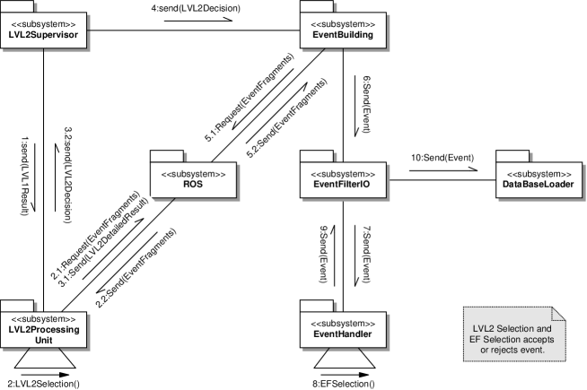
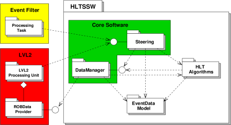
Fig. 5 shows an overview of the HLT data flow hlttp . The LVL2 Supervisor sends the LVL1 result containing ‘Region-of-Interest’ information (e.g. geometrical position of interesting objects identified by LVL1) to a LVL2 Processing Unit. This unit performs the LVL2 selection for the event. It retrieves event data in ‘Regions-of-Interest’ from the Read-Out System (ROS). At the end of the selection process the LVL2 decision is passed back to the Supervisor. In case of a positive trigger decision, the LVL2 detailed result is sent to a dedicated LVL2 ROS. The LVL2 Supervisor sends the decision to the Event Builder, which assembles the full event. The complete event is sent to the Event Filter IO and from there to one of the Event Handlers, which performs the EF selection. EF-selected events are written to mass storage.
Fig. 6 shows a package view of the Event Selection Software elsing which runs in the LVL2 Processing Unit and in the EF Event Handler. It has four building blocks: the Event Data Model defines the structure of the event; the Data Manager handles the event data and is used in LVL2 to retrieve the required raw data on demand from the ROS; the HLT Algorithms provide the algorithmic part of the selection; the Steering controls the full selection process. It is the task of the HLT configuration to configure the Steering.
III.2 The Principle of the HLT Selection
The HLT selection software provides a common framework to implement the LVL2 and EF selection. The software is based on two concepts that are designed to minimize the latency and the amount of raw data to be moved and analyzed. LVL1 provides for each event a set of ‘Region-of-Interest’ coordinates via the RoI Builder. These RoIs are used by the LVL2 Steering to seed to algorithmic processing and to restrict the data access to the regions in the detector identified by the LVL1 system.
The 2nd concept is the so-called ‘step’ processing. The sequence of HLT algorithms to verify a given LVL1 RoI is sub-divided into several logical steps. This allows the Steering to execute in the first step for each RoI those algorithms giving a large rejection power for little data movement and processing. In each subsequent step it is the task of the HLT algorithms to refine the event information using an increasing amount of additional data from different ATLAS sub-detectors. It is important to note that the Steering will execute the first step for all RoIs in one go. Events may be rejected after each step; remaining events are passed to the next step for further processing. For events accepted after the final step a positive trigger decision is transmitted to the LVL2 Supervisior.
The implementation of the Steering of the HLT selection software must to be generic. The HLT selection is data driven by the LVL1 RoIs, while the list of possible HLT algorithm sequences will be configured at run time based on the criteria of the physics signatures in the trigger menu. It was found to be beneficial to abstract the selection process in terms of so-called ‘Trigger Elements’ (TEs). A TE represents a trigger relevant object in the event, for example a LVL1 RoI. In this picture, the HLT selection can be seen as a refinement process of TEs. Each TE implies by its label a physics interpretation, like for example an ‘isolated electron with GeV’ or ‘e20i’. Each physics signature in a trigger menu is defined as a combination of required TEs, for example ‘e20i + mu30i’.
The seeding of the HLT Algorithms is implemented by navigation from the TE to the relevant event data (RoI, clusters, tracks, …). Thereby the Steering only analyses the TE content of an event and requests algorithm processing to refine the information. The details of the specific event data related to each LVL1 RoI are only visible to the concrete HLT algorithm.
III.3 Signatures and Sequence Tables
The basic unit of a step is a ‘sequence’. It consists of a list of input TEs, a list of HLT algorithms to be run on each set of matching input TE combinations found in an event, and one (and only one) output TE that represents the hypothesis of the expected reconstruction result. The complete set of sequences to be run in a given step is called the ‘sequence table’.
At the end of each step the Steering compares the list of validated TEs in an event to so-called ‘signatures’, which are formulated as required TEs or TE combinations. The set of signatures of a given step is called the ‘menu table’. The signatures in the menu table of the final step are called ‘physics signatures’. The physics signatures are defined according to the ATLAS physics program and are the ones that will be visible to the shift crew in the control room, whereas the intermediate ones are visible only for an expert with insight into the configuration scheme.
From the above it is clear that the trigger configuration has to provide a set of menu and sequence tables. This is achieved in a top-down approach starting from a list of physics signatures that is specified for a given ATLAS run. This list is used to derive, in a recursive way, all necessary sequence and menu tables.
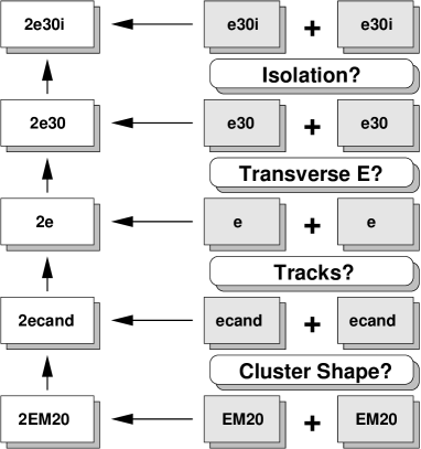
The recursive procedure is illustrated for a simplified example in Fig. 7. The physics signature is ‘two isolated electron candidates with 30 GeV’ or ‘2 e30i’. This signature requires the presence of two final TEs ‘e30i’ in an event. The configuration software has a list of all implemented sequence and checks which sequence has this TE as its output. From the matching sequence is determines the corresponding required input TEs. In the example the ‘e30i’ TE is made from an ‘e30’ TE using an isolation algorithm. Thereby the configuration can derive that two TEs ‘e30’ are required in the step that leads to the physics signature ‘2e30i’. The resulting intermediate signature is ‘2e30’. Similarly, the ‘2e30’ is composed of two ‘e30’ TEs which are made from TEs labeled ‘e’ in an algorithm that requires a minimum transverse energy. In this manner, all intermediate signatures and also the necessary sequences are derived recursively, until the configuration algorithm arrives at input TEs labeled ‘EM20’ that represent the LVL1 electromagnetic RoI objects.
It is worth mentioning that the HLT event decision is derived from the same logical structure, but now using it bottom-up: The HLT selection process starts from the input from LVL1. In the example it would search for two ‘EM20’ TEs. In case these TEs are not present, the signature of the first step (‘2EM20’) cannot be fulfilled and the event would be rejected. If the signature ‘2EM20’ is fulfilled, the sequence of algorithms is executed on each input TE to analyze the cluster shape of the candidate object. The task is to refine the electron selection, rejecting background (mainly jets) using clusters shape variables. In other words, for each ‘EM20’ TE that is considered to be due to an electron, the hypothesis of a TE ‘ecand’ (for ‘electron candidate’) needs to be validated. If an ‘ecand’ is validated for both ‘EM20’ TEs, the signature ‘2ecand’ is fulfilled and the selection will proceed. Otherwise the event will be rejected. In this way the selection is carried out up to the last step that ends with two TEs ‘e30i’.
III.4 Implementation of the HLT Configuration
As in the case of the LVL1 trigger, two XML files are used to define the physics signatures and the list of available sequences for the HLT configuration. The signature file contains SIGNATURE tags that have the a list of TRIGGERELEMENT tags for the required TEs:
<SIGNATURE>
   <TRIGGERELEMENT te_name="..." />
   <TRIGGERELEMENT te_name="..." />
</SIGNATURE>
The ‘te_name’ attribute assigns a label to the TE. The physics menu in the XML file is given by the list of all signatures. The second XML file contains a list of SEQUENCE tags. Each sequence has three different attributes:
<SEQUENCE te_in="..." algo="..." te_out="..." />
to identify the input TEs (‘te_in’), the algorithm(s) to be run on these trigger elements (‘algo’), and the output TE (‘te_out’). The same ‘te_in’ can appear in more than one sequence.
The XERCES DOM API xerces is used to parse the SIGNATURE and SEQUENCE tags in the configuration XML files into an object tree. Afterwards the recursive algorithm described above starts to derive the full set of menu and sequence tables. In practice the menu and sequence tables need additional processing to allow for a realistic menu that consists of several physics signatures. Furthermore, the borderline between LVL2 and EF is defined by assigning the sequences of the first set of steps to LVL2 and the remaining ones to the EF.
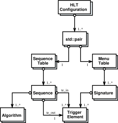
Fig. 8 shows a UML class diagram of the HLT Configuration used to store the HLT configuration information. It is based on a collection of pairs, one instance per step. Each pair combines a MenuTable and a SequenceTable object, each of which holds a vector of Sequence or Siganture objects, respectively. A Signature combines several TriggerElements and a Sequence holds one output TriggerElement , one or more input TriggerElements and a list of Algorithms.
The HLT configuration has been tested as part of the HLT selection software in the offline and in dedicated online test-beds. In the future it is foreseen to combine the configuration of the HLT and LVL1, based on the input menu table of the first HLT step. Thereby a consistent configuration of the complete ATLAS trigger system will be achieved.
IV CONCLUSION
An overview of the ATLAS trigger system has been given, with emphasis on the configuration of the various trigger levels, namely the LVL1 trigger and the HLT. For LVL1 efforts so far concentrated on the configuration of the trigger simulation, with the aim of a common configuration for both the hardware and the simulation software. In the case of the HLT, which is implemented as a software trigger running in processor farms, the configuration software has been tested successfully and used offline and in dedicated online test-beds. Work is now in progress to combine the configuration of the LVL1 trigger and the HLT in order to guarantee a consistent and efficient ATLAS trigger selection strategy.
Acknowledgements.
We would like to thank the ATLAS LVL1 Trigger and Data Acquisition Groups for their contributions to this work and their help in preparing this paper.References
- (1) The ATLAS High Level Trigger group, http://atlas.web.cern.ch/Atlas/GROUPS/ DAQTRIG/HLT/AUTHORLISTS/chep2003.pdf ∗1
- (2) ATLAS Collaboration, “ATLAS Technical Proposal”, CERN/LHCC/94-43; http://atlas.web.cern.ch/
- (3) ATLAS Collaboration, “First-Level Trigger Technical Design Report”, CERN/LHCC/98-14.
- (4) http://xml.apache.org/xerces-c
-
(5)
ATLAS Collaboration, “ATLAS High-Level Triggers, DAQ and DCS Technical Proposal”, CERN/LHCC/2000-17;
ATLAS Collaboration, “ATLAS High-Level Trigger, Data Acquisition and Controls Technical Design Report”, document in preparation. - (6) M. Elsing et al., “Analysis and Conceptual Design of the HLT Selection Software”, ATLAS Note ATL-DAQ-2002-013.
∗1 S. Armstrong, J.T. Baines, C.P. Bee, M. Biglietti, A. Bogaerts, V. Boisvert, M. Bosman, S. Brandt, B. Caron, P. Casado, G. Cataldi, D. Cavalli, M. Cervetto, G. Comune, A. Corso-Radu, A. Di Mattia, M. Diaz Gomez, A. dos Anjos, J. Drohan, N. Ellis, M. Elsing, B. Epp, F. Etienne, S. Falciano, A. Farilla S. George, V. Ghete, S. Gonz lez, M. Grothe, A. Kaczmarska, K. Karr, A. Khomich, N. Konstantinidis, W. Krasny, W. Li, A. Lowe, L. Luminari, H. Ma, C. Meessen, A.G. Mello, G. Merino, P. Morettini, E. Moyse, A. Nairz, A. Negri, N. Nikitin, A. Nisati, C. Padilla, F. Parodi, V. Perez-Reale, J.L. Pinfold, P. Pinto, G. Polesello, Z. Qian, S. Rajagopalan, S. Resconi, S. Rosati, D.A. Scannicchio, C. Schiavi, T. Schoerner-Sadenius, E. Segura, T. Shears, S. Sivoklokov, M. Smizanska, R. Soluk, C. Stanescu, S. Tapprogge, F. Touchard, V. Vercesi, A. Watson, T. Wengler, P. Werner, S. Wheeler, F.J. Wickens, W. Wiedenmann, M. Wielers, H. Zobernig