A novel directional coupler utilizing a left-handed material
Abstract
A novel directional coupler with a left-handed material (LHM)
layer between two single-mode waveguides of usual material is
introduced. The coupling system is analyzed with the supermode
theory. It is shown that such a LHM layer of finite length can
shorten significantly the coupling length for the two
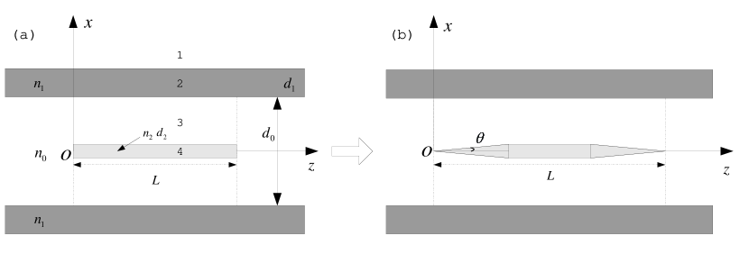
single-mode waveguides. A LHM layer with two slowly tapered ends is used to avoid the reflection loss at the ends.
Index terms—– Directional couplers, left-handed material, supermode theory, optical planar waveguide couplers
I INTRODUCTION
Recently, a new type of electromagnetic materials which have simultaneously a negative electric permittivity and a negative magnetic permeability have generated a great interest ves ; shelby ; pen2 . Such a material is often called a left-handed material (LHM) since the electric field, the magnetic field and the wave vector of an electromagnetic wave propagating in it obey the left-hand rule (instead of the right-hand rule for usual materials). In 1968, Veselago theoretically investigated such a material and predicted some extraordinary properties such as the negative refraction, Doppler shift and Cerenkov radiation, etc ves . Because of the unavailability of LHMs at that time, his idea did not attract much attention until very recently. Smith et al. have demonstrated experimentally recently the phenomenon of negative refraction shelby . Isotropic LHMs have also been introduced (see e.g. iso ). Pendry predicted that a LHM slab can behave like a perfect lens since the LHM slab can amplify evanescent waves pen2 . In this letter, we propose a novel directional coupler with a LHM layer between two straight single-mode waveguides of usual material (i.e., right–handed material (RHM)).
A directional coupler is a fundamental planar lightwave circuit (PLC) performing the functions of splitting and combining. Combined with optical delay lines, directional couplers can be used to construct Mach-Zehnder interferometers (MZIs), interleavers and wavelength division multiplexers/demultiplexers (WDM). The two parallel single-mode (SM) waveguides in the central coupling region of a conventional directional coupler (of PLC type) are usually very close to each other in order to reduce the coupling length. The separation between the two SM waveguides increases gradually in the input and output waveguide regions in order to connect the directional coupler to fibers or two decoupled (well-separated) SM waveguides (to construct e.g. a MZI). Thus, bent waveguides, which introduce some bending loss and increase the size of the device, have to be used in the transition region (see e.g. bend ). In this letter, we show that by putting a LHM layer of finite length in the middle the coupling length for two parallel SM waveguides can be shortened significantly (this can make the device much shorter; it is desirable in a future network that many compact components can be put in an integrated chip). In our novel directional coupler, the two parallel SM waveguides can be well-separated from each other and thus there is no need to use bent waveguides (this is another advantage of the present novel directional coupler).
II FORMULAS FOR CALCULATING THE COUPLING LENGTH
In the design and analysis of directional couplers, the supermode solution gne has been widely used to calculate the coupling length of two parallel waveguides. Compared to the coupled mode theory, the supermode solution method is more accurate and is still valid even the separation between the two waveguides are quite small coup1 . Here we use the supermode solution method to study the novel directional coupler shown in Fig. 1. For a PLC, the effective index method eff can simplify the analysis greatly through converting the three-dimensional model to a two-dimensional model. To increase the coupling between the two SM waveguides, a left-handed material (LHM) layer is placed between them. The refractive indices of the core and the cladding for the SM waveguides are denoted by and , respectively. The two SM RHM waveguides have the same width and the separation between them is . The negative refractive index and width of the LHM layer are denoted by and , respectively. The propagation constants of the two associated supermodes are denoted by (for the symmetric supermode) and (for the antisymmetric supermode). The region between the two vertical dash-dotted lines in Fig. 1 indicates the strong coupling region.
Since the structure is two-dimensional, the electromagnetic fields can be decomposed into the - and -polarized modes. Let us consider the case of -polarization (the -polarization case can be treated in a completely analogous way). Since the two supermodes of this system is either symmetric or antisymmetric about the central line , we only need to study the field distribution in the area . The electric field of a supermode in the four regions (see Fig. 1 (a)) of the central part (with strong coupling) can be written in,
| (1) | |||
| (2) | |||
| (3) | |||
| (4) |
where , , ( and are the propagation constant along the direction and the wave number in vacuum, respectively), and and are the coefficients to be determined. The and signs in Eq. (4) correspond to the symmetric supermode and the antisymmetric supermode, respectively. From the continuity of the tangential electric and magnetic fields at all horizontal boundaries, we obtain the following characteristic equation for the propagation constant of a supermode
| (5) |
where (or ) for the symmetric (or antisymmetric) supermode and ( and are the permittivity and permeability of the cladding, respectively). Compared with the corresponding analysis for a conventional multi-layered RHM structure, the only difference is in the continuity of the magnetic field on the boundary between the layer and the layer (the LHM layer; is negative in the layer while is positive in the layer). After the propagation constants and (for symmetric and antisymmetric supermodes, respectively) are determined from the above equation, the coupling lengths (within which the light is coupled totally from one SM RHM waveguide to the other) for this coupling system can then be calculated by
| (6) |
III NUMERICAL RESULTS AND DISCUSSION
In our simulations, the (effective) refractive indices of the core and cladding are assumed to be and , respectively. We choose the width for each SM RHM waveguide as (where is the cutoff width) to keep the waveguide single-moded for a specific wavelength , and we fix the separation between the two SM waveguides as (i.e., ). Before inserting the LHM layer (i.e., ), Eq. (5) gives a coupling length , which is about 35 centimeter if we choose a typical wavelength for optical communications. Obviously, such a directional coupler is useless in any practical application as the coupling length is too long. From the physical mechanism of the coupling, we see that the coupling can be enhanced effectively (and thus the coupling length can be shortened significantly) if we enlarge the field amplitude of the evanescent wave (of a SM RHM waveguide) penetrating into the core of the other SM RHM waveguide. It is well known that a LHM can amplify evanescent waves (see e.g. pen2 ). Thus, we insert a LHM layer between the two SM RHM waveguides (as shown in Fig. 1(a)) to enhance the coupling. In our numerical simulation, we choose and (i.e., the impedance and refractive index for the LHM layer are matched with the ones for the cladding). The coupling length calculated with Eq. (6) is shown by the solid line in Fig. 2 as the width of the LHM layer increases. From this figure one sees that the coupling length is shortened dramatically when the width of the LHM layer increases. Due to its amplification ability for evanescent waves, the LHM layer enhances effectively the coupling between the two SM RHM waveguides. When the width of the LHM layer increases from to , the coupling length is shortened rapidly from to (less than 100 ).
Now we consider the reflection loss at the start () of the LHM layer, which has a finite length (see Fig. 1(a); the reflection loss at the other end of the LHM layer has the same value). Let an incident wave impinge on one of the SM RHM waveguides and propagate along the direction into our directional coupler. When it meets the start of the LHM layer at , the mismatch between the supermodes at and will cause a reflection loss at the interface . This reflection loss can be estimated from the orthogonality of eigenmodes and an overlap integral method overlap . The dotted line in Fig. 2 shows the reflection loss (in terms of the energy) around the interface as the width of the LHM layer increases. As expected, when there is no LHM layer (i.e., ), the reflection loss at is 0. As the width of the LHM layer increases, the reflection loss starts to appear, however, keeps at a low level until reaches (note that the coupling length is shortened rapidly as the width of the LHM layer increases). The reflection loss starts to increase quickly with the width after it reaches . For example, about of the incident energy will be reflected around the interface when .
To reduce the reflection loss at the two ends of the LHM layer, we use a LHM layer with two slowly tapered ends (see Fig. 1(b)). Almost all the energy can then be coupled into the system (i.e., the reflection loss is negligible) when the tapering angle is small enough. In our simulation, we fix . For such a directional coupler, the propagation constants of the two supermodes vary slowly along the direction and the central strong coupling length should be determined from the following formula
| (7) |
where the total phase difference is determined by the desired splitting ratio of the directional coupler (note that the normalized output powers at the two SM RHM waveguides are and , respectively). When , the coupling length gives the total length of the LHM layer (including the two tapered parts) within which the light is coupled totally from one SM RHM waveguide to the other. This total coupling length is shown by the dashed line in Fig. 2 when the width of the LHM layer (at the central part) increases. When the width of the LHM layer is small, the coupling length is large and the tapering length is vary small (relatively), and thus the difference between the dashed line and the solid line is small in Fig. 2. When the width of the LHM layer becomes large, the coupling length is shortened significantly and consequently the difference between the coupling lengths for the two cases (with and without tapered ends) becomes noticeable in Fig. 2. The tapering length at each end is when . For example, when we increase the width of the LHM layer from to , the total coupling length decreases from to . This length () is about longer than the corresponding coupling length () when the LHM layer has no tapered ends, but is still very short and thus the device can be very compact. In the mean time, the tapering makes the reflection loss at the ends negligible (and thus we do not show it in Fig. 2).
IV CONCLUSION
A novel directional coupler formed by inserting a LHM layer of finite length between two SM RHM waveguides has been introduced. Using the method of supermodes, we have analyzed this coupling system and studied how the coupling length for the two SM RHM waveguides is shortened dramatically as the width of the LHM layer increases. The coupling is enhanced through the amplification of the evanescent waves in the LHM layer. The reflection loss due to the sudden mismatch of supermodes at the two ends of the LHM layer has also been estimated. To reduce this reflection loss, a LHM layer with two slowly tapered ends has been used. The novel directional coupler can shorten the coupling length dramatically without any bent waveguide.
The partial support of National Natural Science Foundation of China under a key project (90101024) and a project (60277018) are gratefully acknowledged.
References
- (1) V.G. Veselago, “The electrodynamics of substances with simulataneously negative values of and ”, Sov. Phys. Usp., vol. 10, pp. 509-514, Jan/Feb. 1968.
- (2) R.A. Shelby, D.R. Smith, S. Schultz, “Experimental Verification of a Negative Index of Refraction”, Science, vol. 292, pp.77-79, Apr. 2001.
- (3) J.B. Pendry , “Negative Refraction Makes a Perfect Lens ”, Phys. Rev. Lett., vol. 85, pp. 3966-3969, Oct. 2000.
- (4) C. Simovski and S.L. He, “Frequency range and explicit expressions for negative permittivity and permeability for an isotropic medium formed by a lattice of perfectly conducting Omega particles”, Phys. Lett. A, vol. 311, pp. 254-263, May. 2003.
- (5) Wang QA, He SL, Wang LR, “A low-loss Y-branch with a multimode waveguide transition section”, IEEE Photonic Tech. Lett., vol. 14, pp. 1124-1126, Aug. 2002.
- (6) H. Gnewuch, J. E. Román, M. Hempstead, J. S. Wilkinson, and R. Ulrich, “Beat-length measurement in directional couplers by thermo-optic modulation”, Opt. Lett., vol. 21, pp. 1189-1191, Aug. 1996.
- (7) L. Tsang, S.L. Chuang, “Improved coupled-mode theory for reciprocal anisotropic waveguides”, J. Lightwave Technol., vol.6, pp. 304-311, Feb. 1988.
- (8) K.H. Lee, W. Steenaart, “Analysis of N N passive optical star coupler based on the normal modes of N input waveguides”,J. Lightwave Technol., vol. 10, pp. 1800-1806, Dec. 1992.
- (9) M.E. Marhic, XM Yi, “Calculation of dispersion in arrayed waveguide grating demultiplexers by a shifting-image method”, IEEE J. Sel. Top. Quant., vol. 8, pp.1149-1157, Nov/Dec. 2002.