Effects of boundary roughness on a -factor of whispering-gallery-mode lasing microdisk cavities
Abstract
We perform numerical studies of the effect of sidewall imperfections on the resonant state broadening of the optical microdisk cavities for lasing applications. We demonstrate that even small edge roughness () causes a drastic degradation of high- whispering gallery (WG) mode resonances reducing their -values by many orders of magnitude. At the same time, low- WG resonances are rather insensitive to the surface roughness. The results of numerical simulation obtained using the scattering matrix technique, are analyzed and explained in terms of wave reflection at a curved dielectric interface combined with the examination of Poincaré surface of sections in the classical ray picture.
During recent years significant experimental efforts were put forward towards investigation of laser emission of dielectric and polymeric low-threshold microdisk cavities Introduction ; Nockel ; Slusher_1992 ; Berggren ; Fujita ; Gayral ; Seassal ; Inganas ; Polson2002 . The high efficiency of lasing operation in such devices is related to the existence of natural cavity resonances known as whispering gallery (WG) modes. The origin of these resonances can be envisioned in a ray optic picture, wherein light is trapped inside the cavity through total internal reflections on the cavity-air boundary.
One of the most important characteristics of cavity resonances is their quality factor (-factor) defined as (Stored energy)/(Energy lost per cycle). The -factor of a microdisk cavity is mostly governed by a radiative leakage through the curved interface due to diffraction. An estimation of the -factor in an ideal disk cavity of a typical diameter m for a typical WG resonance gives (see below, Eq. (4)). At the same time, experimental measured values reported so far are typically in the range of or lower. A reduction of a -factor may be attributed to a variety of reasons including side wall geometrical imperfection, inhomogeneity of the height and diffraction index of the disk, effects of coupling to the substrate or pedestal and others. Several experimental studies point out side wall imperfections as the main factor affecting the -factor of the cavityFujita ; Gayral ; Seassal . An indirect indication of the importance of this factor in disc microcavities is provided by the observation that typical -factors of spheroidal microcavities are several orders of magnitude higher than those of microdisk of comparable dimensionsIntroduction ; Ilchenko . This is believed to be due to superior quality of the microsphere surfaces where boundary scattering may be limited by thermal fluctuations of the surface only. Therefore, the effect of surface roughness appears to be of crucial importance for the design, tailoring and optimization of -values of lasing mikrodisk cavities. To the best of our knowledge, this effect has not been considered to date and warrants an investigation.
In order to compute the resonant states of a cavity of an arbitrary shape we develop a new approach based on the scattering matrix technique. The scattering matrix technique is widely used in analyse of waveguidesRussian as well as in quantum mechanical simulationsDatta . This technique was also used for an analysis of resonant cavities for geometries when the analytical solution was availableHentschel . Note that because the problem at hand requires a fine discretization of the geometry, commonly used time-domain finite difference methodsLi would be prohibitively expensive in terms of both computer power and memory. While a detailed description of the calculations will be given elsewhere, we present here the essence of the method.
We consider a two-dimensional cavity with the refraction index surrounded by air. Because the majority of experiments are performed only with the lowest transverse mode occupied, we neglect the transverse (-) dependence of the field and thus limit ourself to the two-dimensional Helmholtz equation. We divide our system in an outer and an inner regions. In the outer region the refraction index is independent of the coordinate and the solution to the Helmholtz equation can be written in polar coordinates in the form
| (1) |
for TM (TE)-modes, are the Hankel functions of the first and second kind of order describing respectively incoming and outgoing waves, .
We define the scattering matrix in a standard fashionRussian ; Datta ; Hentschel , , where are column vectors composed of the expansion coefficients for incoming and outgoing states in Eq. (1). The matrix element gives the probability amplitude of scattering from an incoming state into an outgoing state . In order to apply the scattering matrix technique we divide the inner region into narrow concentric rings. At each -th boundary between the rings we introduce the scattering matrix that relates the states propagating (or decaying) towards the boundary, with those propagating (or decaying) away of the boundary. The matrices are derived using the requirement of continuity of the tangential components for the - and -field at the boundary between the two dielectric media. Successively combining the scattering matrixes for all the boundariesRussian ; Datta , , we can relate the combined matrix to the scattering matrix .
To identify the resonant states of a resonant cavity we introduce the Wigner-Smith time-delay matrix , Smith ; Nockel ; Hentschel where the diagonal elements give a time delay experienced by the wave incident in -th channel and scattered into all other channels. The -value of the cavity is , where is the total time delay averaged over all incoming channels Mello ; Nockel ; Hentschel ,
| (2) |
are the eigenvalues of the scattering matrix , is the total phase of the determinant of the matrix , .
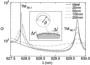
Figure 1 shows calculated -values of the disk resonant cavity for different surface roughnesses for TM modes in some representative wavelength interval. Note that an exact experimental shape of the cavity-surface interface is not available. We thus model the interface shape as a superposition of random Gaussian deviations from an ideal circle of radius with a maximal amplitude and a characteristic distance between the deviation maxima (see illustration in inset to Fig. 1).
The solid curve in Fig. 1 corresponds to an ideal disk cavity without imperfections. Resonant states of an ideal disk (as well as the bound states of the corresponding closed resonator) are characterized by two numbers, (see Eq. (1) and . The index is a radial wave number that is related to the number of nodes of the field components in the radial direction . The angular wave number can be related to the angle of incidence in a classical ray picture Nockel
| (3) |
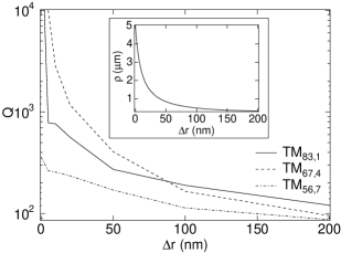
The dependence of the averaged -values on the surface roughness is summarized in Fig. 2 for several representative resonances. A common feature of all high- resonances is a dramatic decrease of their maximal -value that takes place for very small values of . For example, a -value of at he resonant state TM83,1 drops from for an ideal disk to for surface roughness of only nm. In contrast, low- resonances show a rather slow decrease in their -values over the range of variation of . For example, for the same surface roughness the -value of the resonant state TM56,7 decreases only by a factor of 1.5, dropping to .
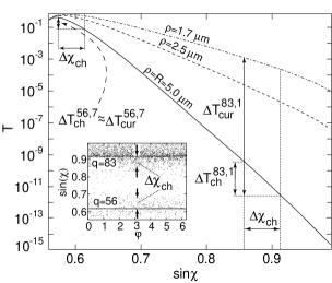
In order to understand these features we combine a Poincaré surface of section (SoS) method with an analysis of ray reflection at a curved dielectric interface Snyder . The -value of the cavity can be related to the transmission probability of an electromagnetic wave incident on a curved interface of radius by Hentschel_rapid (this expression is valid for large angles of incidence when ). In turn, for , the transmission probability reads Snyder
| (4) |
where is the classical Fresnel transmission coefficient for an electromagnetic wave incident on a flat surface, is an angle of total internal reflection. Figure 3 illustrates that decreases exponentially as the difference grows.
The inset to Fig. 3 depicts the Poincaré SoS for two states with and shown in Fig. 1, where the initial angle of incidence of launched rays is related to the angular number by Eq. (3). The SoS demonstrates that initially regular dynamics of an ideal cavity transforms into a chaotic one even for a cavity with maximum roughness nm. in Fig. 3 indicates the estimated increase in the transmission coefficient due to the broadening of the phase space, , as extracted from the Poincaré SoS for the state with . This corresponds to the decrease of . This value is much smaller that the actual calculated decrease of the -factor for the high- resonance TM83,1.
To explain the rapid degradation of high- resonances, we concentrate on another aspect of the wave dynamics. Namely, the imperfections at the surface boundary effectively introduce a local radius of surface curvature that is distinct from the disk radius (see illustration in Fig. 1). One may thus expect that with the presence of a local surface curvature, the total transmission coefficient will be determined by the averaged value of rather than by the disk radius . The dependence of on surface roughness for the present model of surface imperfections is shown in the inset to Fig. 2. Figure 3 demonstrates that the reduction of the local radius of curvature from m (ideal disk) to m (nm) causes an increase of the transmission coefficient by . This estimate, combined with the estimate based on the change of is fully consistent with the -factor decrease shown in Figs. 1,2. We thus conclude that the main mechanism responsible for the rapid degradation of high- resonances in non-ideal cavities is the enhanced radiative decay through the curved surface because the effective local radius (given by the surface roughness) is smaller that the disk radius .
For the case of low- resonances the change in the transmission coefficient due to enhanced radiative decay is of the same magnitude as the change due to the broadening of the phase space caused by the transition to chaotic dynamics (as illustrated in Fig. 3 for the resonance TM56,7). Therefore, both these factor play comparable roles in degradation of the low- WG resonances.
It is worth mentioning that one often assumes that long-lived high- resonances in idealized cavities (e.g. in ideal disks, hexagons, etc.) are not important for potential application in optical communication or laser devicesHentschel ; Wiersig because of their extremely narrow width. Our simulations demonstrate that it is not the case, because in real structures the -values of these resonances becomes comparable to those of intermediate- resonances already for small or moderate surface roughness of nm.
To conclude, our results highlight the importance of surface roughness for the performance of microcavities for laser applications, and provide estimations on surface roughness that might be instrumental for device design and fabrication.
We thank Olle Inganäs for stimulating discussions that initiated this work and we thankful to Stanley Miklavcic and Sayan Mukherjee for many useful discussions and conversations. A.I.R. acknowledges financial support from SI and KVA.
References
- (1) Y. Yamamoto and R. E. Slusher, Physics Today, June 1993, p.66; S. Arnold, American Scientist 89, 414 (2001).
- (2) J. U. Nöckel and R. K. Chang, in Cavity-Enhanced Spectroscopies, R.D. van Zee and J.P.Looney, eds., (Vol. 40 of ”Experimental Methods in the Physical Sciences”, Academic Press, San Diego, 2002), pp. 185-226.
- (3) S. L. McCall, A. F. J. Levi, R. E. Slusher, S. J. Pearton, and R. A. Logan, Appl. Phys. Lett. 60, 289 (1992).
- (4) A. Dodabalapur, M. Berggren, R. E. Slusher, Z. Bao, A. Timko, P. Schiortino, E. Laskowski, H. E Katz, and O. Nalamasu, IEEE Journal of selected topics in quantum electronics, 4, 67 (1998).
- (5) M. Fujita, K. Inoshita, and T. Bata, Electronic Lett. 34, 278 (1998).
- (6) B. Gayral, J. M. Gérard, A. Lemaître, C. Dupuis, L. Manin, and J. L. Pelouard, Appl. Phys. Lett. 75, 1908 (1999).
- (7) C. Seassal, X. Letartre, J. Brault, M. Gendry, P. Pottier, P. Viktorovitch, O. Piquet, P. Blondy, D. Cros, O. Marty, J. Appl. Phys. 88, 6170 (2000).
- (8) M. Theander, T. Granlund, D. M. Johanson, A. Ruseckas, V. Sundström, M. R. Andersson, and O. Inganäs, Adv. Mater. 13, 323 (2001).
- (9) R. C. Polson, Z. Vardeny, and D. A. Chinn, Appl. Phys. Lett. 81, 1561 (2002).
- (10) V. S. Ilchenko, M. L. Gorodetsky, X. S. Yao, and L. Maleki, Optics Lett. 26 257 (2001).
- (11) V. V. Nikolsky, T. I. Nikolskaya, Decomposition approach to the problems of electrodynamics (Nauka, Moskow, 1983), (in Russian).
- (12) S. Datta, Electronic Transport in Mesoscopic Systems (Cambridge University Press, Cambridge, 1995).
- (13) M. Hentschel and K. Richter, Phys. Rev. E 66, 056207 (2002).
- (14) B.-J. Li and P.-L. Liu, IEEE J. Quantum Electron. 33, 1489 (1997).
- (15) F. T. Smith, Phys. Rev, 118, 349 (1960).
- (16) M. Bauer, P. A. Mello, and K. W. McVoy, Z. Physik A 293, 151 (1979).
- (17) M. Hentschel and H. Schomerus, Phys. Rev. E. 65, 045603(R) (2002).
- (18) J. Wiersig, J. Opt. A: Pure Appl. Opt. 5, 53 (2003).
- (19) A. V. Snyder and J. D. Love, IEEE Trans. Microwave. Theor. Techn. MTT-23, 134 (1975).