Giant Goos-Hänchen effect at the reflection from left-handed metamaterials
Abstract
We study the beam reflection from a layered structure with a left-handed metamaterial. We predict a giant lateral (Goos-Hänchen) shift and splitting of the beam due to the resonant excitation of surface polaritons with a vortex-like energy flow between the right- and left-handed materials.
pacs:
41.20.Jb, 42.25.Bs, 78.20.Ci, 42.70.QsAs is known, a totally reflected beam experiences a lateral displacement from its position predicted by the geometric optics because each of its plane-wave components undergoes a different phase change Goos:1947-333:AP . For the beam reflected from an interface, the lateral beam shift (the so-called Goos-Hänchen effect) is usually much less than the beam width. However, larger beam shifts may occur in the layered systems supporting surface waves, which are able to transfer energy along the interface. Such surface waves are not excited at a single interface because the phase-matching condition between the incident and surface waves are not satisfied. However, a surface polariton can be excited in a layered structure, when the beam is incident at the angle larger than the angle of the total internal reflection. Excitations of polaritons take place in two well known geometries of the attenuated beam reflection (used e.g. for the measurements of the dielectric permittivity of solids): (i) glass prism-air-silver structure (the so-called Otto configuration) and (ii) prism-silver film-air structure (the so-called Kretchmann configuration) (see, e.g., Ref. Chuang:1986-593:JOSA and references therein).
The extensive study of novel microstructured materials with negative refraction recently fabricated experimentally shelby , the so-called left-handed metamaterials, demonstrates that an interface between right- and left-handed material supports surface polaritons of TE and TM types Ruppin:2000-61:PLA ; Shadrivov:unpub , which can enhance dramatically the Goos-Hänchen effect because surface waves can transfer the energy along the interface. In this Letter, we predict and analize the giant Goos-Hänchen effect in the structure (i) (the Otto configuration), where the third medium is substituted by a left-handed metamaterial.
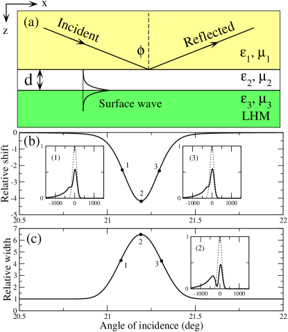
We consider a two-dimensional geometry shown in Fig. 1(a), where the beam, incident from an optically dense medium () at the angle larger than the angle of the total internal reflection, is reflected from the interface. We assume that the third medium is separated by a gap (which we call the second medium), and it is made of a left-handed metamaterial which possesses both negative real parts of dielectric permittivity and magnetic permeability . The interface between the second and third media supports surface waves which can be excited resonantly when the tangential component of the wave vector of the incident beam coincides with the propagation constant of the surface polariton. In such a case, the surface wave can transfer energy along the interface leading to a great enhancement of the lateral beam shift.
The Goos-Hänchen shift can be calculated analytically as Brekhovskikh:Waves , when the phase of the reflection coefficient is a linear function of the wave vector component along the interface, across the spectral width of the beam. The (standard) lateral beam shift has been calculated for the reflection from layered structures with left-handed materials, for the cases of a single interface Berman:2002-067603:PRE and for a periodic structure of alternating right- and left-handed layers Shadrivov:2003-:APL .
In our geometry [see Fig. 1(a)], the reflection coefficient for the TE-polarized plane monochromatic [] wave can be found as
| (1) |
where , , where , is the gap thickness, and is the speed of light in vacuum. Here, we consider the TE polarized waves, but the results are qualitatively similar for the TM polarized waves.
We consider an incident beam of the Gaussian shape, , where is the width of the beam, determines the angle of incidence , , and is the propagation constant in the fist medium, . The reflected field is found in a standard way
| (2) |
where is the Fourier spectrum of the incident beam.
Larger lateral beam shifts are expected at the angles of incidence such that the beam spectrum contains the components with the same as the propagation constant of the surface waves. As has been shown recently, both forward and backward surface polaritons can exist at the left-handed interface Shadrivov:unpub , depending on the parameters and . Excitation of the forward surface waves results in the energy transfer in the direction of incidence. A negative shift of the beam is obtained when the backward surface waves are excited, this corresponds to the parameters and .
We define the relative beam shift as the normalized first momentum of the electric field of the reflected beam, , where
| (3) |
The values correspond to the beam shift much smaller then the beam width, while corresponds to a giant Goos-Hänchen shift. The second momentum characterizes a change of the beam width during the reflection, .
We chose the following parameters of the media: , , , . The propagation constant of surface polaritons can be found from the relation , and for these parameters the surface waves at the interface are backward propagating. Figures 1(b,c) show the dependence of and on the angle of incidence at and , respectively. We observe a distinctive resonant dependence of the beam shift, and the maximum corresponds to the phase matching condition .
In the inset (2) of Fig. 1(c), two distinctive peaks in the reflected beam are observed. The first peak corresponds to a mirror reflection, while the second peak is shifted from the incident beam and it appears due to the excitation of surface waves. At the resonance, the lateral beam shift becomes larger than the beam width. The double-peak structure appears only for narrow beams, when the beam spectrum is wider than the spectrum width of the surface mode, the later can be found as a width of the resonance shown in Fig. 1(b). The components of the beam spectrum outside this region are reflected in a mirror-like fashion, while the spectrum components near the resonance transform into a surface wave, being responcible for the second peak in the shifted reflected beam. For wider beams, such that their spectrum is completely falls into the surface mode excitation line, only the shifted peak appears. With an increase of the beam width, though, the relative beam shift decreases due to the fact that the absolute shift of the beam grows slower than the beam width.
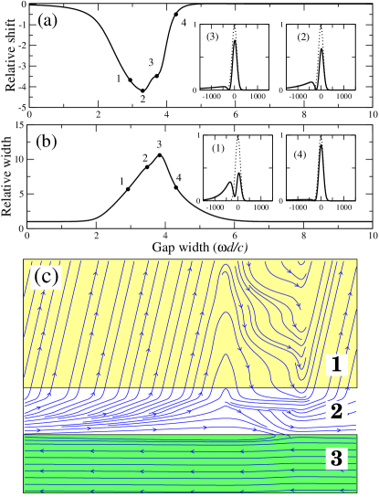
Figures 2(a-c) show the beam shift and width vs. the normalized gap thickness and the structure of the energy flow. The resonances observed in Figs. 2(a,b) have simple physical explanation. Indeed, when the gap is absent () or small, no surface wave is excited, and the beam shift is negligible. Increasing the gap width, one increases the quality factor of the surface mode, thus increasing its propagation distance and the reflected beam shift. Similarly, for large the surface wave is not excited, and the reflected beam shift becomes small again.
To understand deeper the physical mechanism for the giant Goos-Hänchen shift, we calculate the energy flow for the beam reflection and compare it with the results for the right-hand media Lai:2000-7330:PRE . Figure 2(c) shows the structure of the energy flow for the case of a negative lateral shift. The strongly curved flow lines in the upper medium correspond to the interference of the incident and mirror-like reflected beams. The finite-extension surface wave excited in a slab along the interface has a distinctive vortex-like structure Shadrivov:PRE . This surface wave transfers the energy in the negative direction, and then the energy is reflected from the interface as a shifted beam.
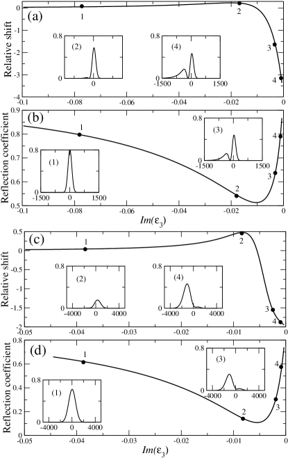
To make our predictions more realistic, we study the effect of losses always present in left-handed materials. We introduce losses by adding the imaginary parts to the dielectric permittivity and magnetic permeability . In particular, we take and vary the imaginary part of . We notice that the losses in the left-handed medium affect mostly the surface waves and, therefore, the major effect produced by the losses is observed for the strongly shifted beam component.
We distinguish two limiting cases. When the beam is narrow, i.e. its spectral width is large, only a part of the beam energy is transferred to surface waves, while the other part is reflected. This case is shown is Figs. 3(a,b). In this case the increase of losses, i.e. the increase of the absolute value of , results in the suppression of the second peak in the reflected beam, which is due to the surface wave excitation. The growth of the amplitude of the mirror-like reflected beam can be explained by a detuning from the resonance between the incident wave and the surface polariton.
For a wide beam with a narrow spectrum, almost all energy of the beam is transferred into a surface wave and, therefore, the lateral shift becomes strongly affected by the losses in the left-handed medium, as shown in Fig. 3(c). Figure 3(d) show the dependence of the reflection coefficient on the imaginary part of the dielectric permittivity in the third medium.
In conclusion, we have described the Goos-Hänchen shift and splitting of a beam totally reflected from a layered structure with a left-handed metamaterial. The giant lateral shift of the beam is explained by the resonant excitation of surface vortex-like polaritons at the interface between the right- and left-handed materials. The beam shift can be both positive and negative, depending on the type of the surface waves excited at the interface. We believe that the giant enhancement of the lateral shift of the reflected beam can be employed for direct measurements of the parameters of left-handed materials.
References
- (1) F. Goos and H. Hänchen, Ann. Physik 1, 333 (1947).
- (2) S. Chuang, J. Opt. Soc. Am. B 3, 593 (1986).
- (3) R.A. Shelby, D.R. Smith, and S. Schultz, Science 292, 77 (2001).
- (4) R. Ruppin, Phys. Lett. A 277, 61 (2000).
- (5) I.V. Shadrivov, A.A. Sukhorukov, Yu.S. Kivshar, A.A. Zharov, A.D. Boardman, and P. Egan, submitted (2003).
- (6) See, e.g., L. Brekhovskikh, Waves in Layered Media (New York, Academic Press, 1980).
- (7) P. Berman, Phys. Rev. E 66, 067603 (2002); A. Lakhtakia, Electromagnetics 23, 71 (2003); R.W. Ziolkowski, Opt. Express 11, 662 (2003).
- (8) I.V. Shadrivov, A.A. Sukhorukov, and Yu.S. Kivshar, Appl. Phys. Lett. 82, June 2 (2003).
- (9) See, e.g., H. Lai, C. Kwok, Y. Loo, and B. Xu, Phys. Rev. E 62, 7330 (2000).
- (10) I.V. Shadrivov, A.A. Sukhorukov, and Yu.S. Kivshar, Phys. Rev. E 67, 0576XX (2003).