Observed photodetachment in parallel electric and magnetic fields
Abstract
We investigate photodetachment from negative ions in a homogeneous 1.0 Tesla magnetic field and a parallel ac electric field of 10 V/cm. A theoretical model for detachment in combined fields is presented. Calculations show that a field of 10 V/cm or more should considerably diminish the Landau structure in the detachment cross section. The ions are produced and stored in a Penning ion trap and illuminated by a single-mode dye laser. We present preliminary results for detachment from showing qualitative agreement with the model. Future directions of the work are also discussed.
pacs:
32.80.Gc, 03.65.NkI INTRODUCTION AND MOTIVATION
One of the long-term objectives of photodetachment studies has been to shed light on electron correlation effects and other electron-atom interactions. One way to enhance photodetachment studies is to add external electric or magnetic fields. These potentials create conditions in negative ions not found in neutral atoms, and permit comparisons with phenomena observed in neutral atom photoionizaton. For example, photodetachment in a static electric field environment releases an electron that experiences an acceleration analogous to that of freefall. External fields permit studies of interference phenomena and provide insight into the connection between quantum mechanics and semiclassical closed-orbit theories. A large amount of attention, both theoretical and experimental, has been given to photodetachment in the presence of external fields Manakov et al. (2000); Blumberg et al. (1978, 1979); Fabrikant (1981); Demkov et al. (1982); Stewart et al. (1988); Baruch et al. (1990, 1992); Gibson et al. (1993a, b, 2001); Du and Delos (1988a, b); Fabrikant (1994); Wong et al. (1988); Rau and Wong (1988); Krause (1990); Bryant et al. (1987); Fabrikant (1991); Wang and Starace (1997); Peters and Delos (1993a, b); Peters et al. (1994, 1997); Liu and Wang (1997a, b); Kramer et al. (2001); Blondel et al. (1996, 1999); Kramer et al. (2002); Bracher et al. (2003).
Photodetachment can be thought of as the latter half of a collision between an electron and a neutral atom. In general, the effect of an external field is to cause a portion of the out-going electron wave function to return to the atomic core, where additional interactions may occur. For example, an electric field creates a potential slope, and the electron wave function travelling uphill is eventually reflected and revisits the core. If the coherence time of the transition is long compared to the reflection time, interference occurs between the parts of the wave function emitted in the upward and downward directions. The time difference, and thus the relative phase between the two waves, depends on the detached electron’s energy and momentum, and diminishes with increasing applied field. The interference gives rise to oscillatory structure in the detachment cross section depending on the relative phase between the waves. The effect has been observed and discussed in numerous papers Fabrikant (1981); Demkov et al. (1982); Stewart et al. (1988); Baruch et al. (1990, 1992); Gibson et al. (1993a, b, 2001); Blondel et al. (1996, 1999); Kramer et al. (2002); Bracher et al. (2003). Throughout the reflection process the electron wave function spreads, unconstrained, in the directions perpendicular to the field. Thus, for a given energy above threshold, a larger electric field causes a larger portion of the wave function to revisit the core, yielding a larger interference amplitude. Most of the experimental observations have employed a field on the order of or more in order to resolve the oscillatory structure in the detachment rate Stewart et al. (1988); Baruch et al. (1990, 1992); Gibson et al. (1993a, b, 2001).
A similar interference occurs in the presence of a magnetic field, whose effect is to constrain and quantize the motion of the outgoing electron in the plane normal to the magnetic field Landau and Lifshitz (1991). The field-free detachment threshold is replaced by a series of Landau thresholds in the cross section at uniformly spaced photon energies corresponding to the cyclotron states Blumberg et al. (1978, 1979). This periodic structure in the cross section arises from the outgoing electron wave function constructively interfering with itself, as the orbiting electron revisits the core once every cyclotron period. This interference structure is in one sense more apparent than that produced by an electric field because the magnetic field confines the electron in two dimensions, and consequently a larger portion of the wave function returns to the core. Similar structure has also been observed in photoionization in a magnetic field Reinhardt (1983); Du and Delos (1987, 1988a).
Interference is suppressed if the cyclotron-orbiting electron does not strictly return to the core. This situation can be brought about in a couple of ways. One is to introduce a small, static electric field parallel to the magnetic field. Such a field tends to accelerate the electron away from the ion core along the fields’ axes, diminishing or even eliminating the dramatic interference of the cyclotron states Peters et al. (1994, 1997); Liu and Wang (1997a, b). The electric field effectively “opens” the closed cyclotron orbits. Earlier quantum mechanical calculations Du (1989); Fabrikant (1991), as well as those in this paper, show that a field on the order of 10 V/cm should significantly reduce the Landau structure observed in the detachment cross section. A commensurate prediction can be made from a semiclassical calculation assuming that, in order to have constructive interference, the electron must return to the atomic core within half a Bohr wavelength in one cyclotron period. Furthermore, the motional Stark field experienced by a thermally energetic ion affects the interference. In the ion’s rest frame, a motional electric field perpendicular to the magnetic field causes the electron to drift away from the core, diminishing resolution of magnetic field structure in the photodetachment rate. Again, theoretical calculations, both quantum mechanical and semiclassical, predict that a motional field on the order of 10 V/cm or more tends to wash out the cyclotron structure found in the magnetic field-only cross section Fabrikant (1991); Peters and Delos (1993a).
Experimentally, it is common for stray electric fields to be present (such as that used in a Penning trap, discussed below, or motional Stark fields), so it is important to understand how such fields affect the detachment spectrum. Although detachment in combined external fields has been discussed extensively in the literature, it has received little experimental attention Bryant et al. (1987); Fabrikant (1991); Wang and Starace (1995, 1997); Peters and Delos (1993a, b); Peters et al. (1994, 1997); Du (1989); Liu and Wang (1997a, b). In this paper we present a theoretical prediction for detachment in combined, parallel external fields. We then describe an experiment to observe detachment from in parallel fields of 1.0 Tesla and 10 V/cm. Preliminary results are shown to be in at least qualitative agreement with the model, and finally, future directions for this work are discussed.
II Theoretical Description
For a theoretical analysis of the photodetachment rate, we employ the quantum source formalism. In this approach the scattering event is divided into two separate stages, absorption of a photon and subsequent emission of the photoelectron into the external field environment. Details of the method, which is equivalent to the leading order of conventional scattering theory, are presented in a recent publication Bracher et al. (2003). In near-threshold photodetachment, the emitting ion is conveniently described as a pointlike source of electrons, the dynamics of which follow from the quantum propagator for the external potential. Particularly simple expressions are found for s-wave detachment in a uniform electric field Kramer et al. (2002). There, our predictions for both the total detachment cross section and the spatial distribution of the photoelectrons are in excellent agreement with the photocurrent spectrum recorded by Gibson et al. Gibson et al. (1993a, 2001) and the photodetachment microscope images recorded by Blondel and colleagues Blondel et al. (1996, 1999), respectively.
II.1 Source model of photodetachment
In the quantum source picture, the motion of a photoelectron that is emitted with an initial kinetic energy close to zero is governed by the modified Schrödinger equation:
| (1) |
Here, we modelled the emitting ion as a pointlike entity, and subsumed the details of the laser-ion interaction in the source strength parameter . (In –wave detachment, the convenient point-like form of the r.h.s. in Eq. (1) emerges from the dipole interaction term in the limit , as the extended initial wavelength of the photoelectron effectively obliterates the detailed source structure. See also Ref. Bracher et al. (2003).) The solution to (1) is given by the energy Green function describing an outgoing wave in the external potential: . The energy Green function, in turn, is linked to the familiar time-dependent quantum propagator by a Laplace transform Economou (1983):
| (2) |
In this context, we are merely interested in the total particle current transported by the wave . Integration over a surface enclosing the point source immediately yields an expression for the detachment rate:
| (3) |
A general expression for the quantum propagator of electrons in uniform electric and magnetic fields at arbitrary angles was given by Nieto Nieto (1992). After insertion in (3), we find from (2) the detachment rate:
| (4) | |||||
where is the Larmor frequency, and denote the electric field components parallel and perpendicular to the magnetic field, respectively.
While Eq. (4) yields the detachment rate for a stationary ion undergoing any particular transition in an arbitrary field geometry, we have to keep in mind that in the actual experiment, (i) the ions are moving in the trap, (ii) an external electric field accelerates the ions, and, (iii) transitions between different magnetic sublevels with generally differing source strength parameters and electron excess energies are occurring simultaneously. We assess these complications below.
II.2 Thermal motion of the ions
The source model, formally expressed in the stationary Schrödinger Eq. (1), implicitly requires that the emitting ion is at rest. Obviously, this condition is not met by the trapped ions which possess an average kinetic energy , where denotes the effective temperature of the ion cloud. To be specific, in the following we assume thermal equilibrium, i. e., the (kinetic) momentum distribution of the cloud is given by Maxwell’s familiar expression:
| (5) |
Here, amu is the mass of the sulfur ions. To obtain the proper detachment rates for a moving ion, we switch to its rest frame of reference. The transformation between the laboratory frame and the rest frame involves a Lorentz boost operation that alters the electric and magnetic fields perceived by the ion Jackson (1975). Since the ion momentum is small, , we neglect quadratic and higher contributions in . This approximation leaves the magnetic field unchanged, while the electric field is augmented by a motional electric field that is perpendicular to and :
| (6) |
Clearly, the additional electric field compensates for the magnetic Lorentz force exerted on the moving ion in the laboratory frame.
Beside the uniform fields present in the trap, the change of reference frame also affects the frequency of the detaching laser beam, and hence the photon energy . The parameter appearing in the Green function (2) is the excess energy of the photoelectron, i. e., the difference between and the electron affinity of the negative ion. The Doppler corrected electronic energy in the rest frame of the ion is given in leading order by:
| (7) |
where denotes the unit vector in direction of the laser beam. The corrections (6) and (7) cause a dependence of the detachment rate on the ionic momentum : . In the experiment, however, only the average detachment rate is accessible which follows from (4) after integration over the thermal Maxwell distribution (5):
| (8) |
We finally mention that the detachment rate in principle depends not only on the momentum of the ions, but also on their position in the trap. After all, an electric quadrupole is used to confine the ions in the axial direction which gives rise to an additional electric field that varies linearly with . However, this field is comparatively weak, and while it can be incorporated into the source formalism without fundamental difficulties, for the sake of simplicity we neglect it here. Furthermore, this approximation facilitates direct comparison of the source model with the theory put forward by Blumberg et al. Blumberg et al. (1979).
II.3 Time-dependent external field
In section II.1, we obtained an expression for the detachment rate (4) that was derived under the condition of a static electric field . Obviously, this field accelerates the ion cloud, and under truly static conditions, its center would settle into a new equilibrium position in the quadrupole potential that effectively eliminates the electric field. Our setup avoids this problem by driving the ions using an oscillating external field whose frequency considerably exceeds the resonance frequency of the trap , but still falls far short of the typical frequencies of electronic motion ( Hz) Foo . Under these circumstances, photodetachment takes place in a quasi-static external electric field , where , while the measurement extends over many periods of the electric field amplitude. Similar to (8), the effective photodetachment rate then is given by the average of over a complete period of the phase angle of the external field:
| (9) |
At this point, we note that the momentum distribution (5) in the driving external field becomes dependent on the phase angle : . However, in the configuration used in our experiment, is oriented parallel to the magnetic field axis, while the laser beam points in the perpendicular direction. It immediately follows that the modified momentum distribution does not affect the corrections (6) and (7). We thus may combine (8) and (9) to find the effective detachment rate for any individual transition:
| (10) |
where and . Inserting the integral representation (4) for the intrinsic current , we find that both integrations in (10) can be carried out analytically, as the integrand is Gaussian in the momentum, and the phase average can be expressed as a Bessel function of order zero Abramowitz and Stegun (1965). We obtain the lengthy result:
| (11) |
where the functions , read:
| (12) | |||||
and
| (13) | |||||
At zero temperature and vanishing electric field, these expressions reduce to the original expression for the detachment rate (4). At this stage, only the temporal integration remains. Choosing a suitable path of integration allows for accurate evaluation of (11). We deform the integration path into the complex plane (carefully avoiding the singularities of the integrand) and perform the integration numerically.
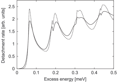
In Fig. 1 we show typical results for different ionic temperatures in a purely magnetic field. To compare with the earlier results by Blumberg et al., we used the same parameter set as in Fig. 2 of Ref. Blumberg et al. (1979) for the dashed curve. Both calculations are in excellent agreement, although they are obtained by quite different methods: Blumberg et al. use a sum over Landau levels to represent the current, and subsequently perform a numerical thermodynamic average. The more general approach presented here allows to incorporate an electric, even time-dependent field at an arbitrary angle. Despite the inclusion of these additional features, a single numerical integration suffices to accomplish the calculation of the properly weighted detachment rate. With decreasing temperature, the Landau levels become more pronounced, while the additional modulations visible in Fig. 1 persist. They may be traced to the perpendicular motional electric field (6).
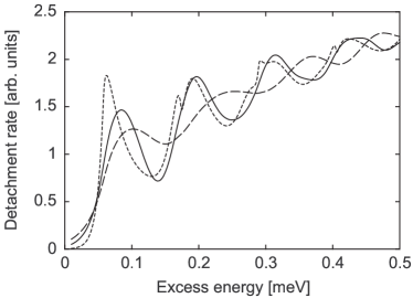
The effects of the additional oscillating parallel field are illustrated in Fig. 2. Two major trends are easily discernible: First, the resolution into discrete Landau levels loses contrast with increasing electric field. In particular, the substructure seen in Fig. 1 is absent. For the higher value of the electric field displayed in the figure ( V/cm), the shape of the detachment rate spectrum is already reminiscent of the “staircase” appearance characteristic for –wave detachment in a purely electric external field Gibson et al. (1993a, 2001); Fabrikant (1994); Bracher et al. (2003); Kramer et al. (2002). The other conspicuous feature in Fig. 2 is a consistent shift of the photocurrent maxima towards higher energies. For a qualitative explanation, we note that in a purely magnetic field, the current (4) generated by an –wave point source becomes singular at the Landau level thresholds : Blumberg et al. (1979), where denotes a constant. (Inclusion of the final-state interaction with the emerging neutral atom corrects the unphysical behavior of the cross section at , as discussed in Refs. Clark (1983); Sadeghpour et al. (2000). However, the modification is of little practical relevance here Greene (1987).) An additional parallel electric field removes the singularity and replaces the root by the square of an Airy function Fabrikant (1991); Du (1989); Wang and Starace (1995); Kramer et al. (2001):
| (14) |
where we introduced the parameter . As adopts its maximum at Abramowitz and Stegun (1965), the maxima of the current are moved to energies . We thus expect a shift of the maxima in the averaged detachment rate (11) proportional to , i. e., that scales with . This conjecture is supported by numerical calculations.
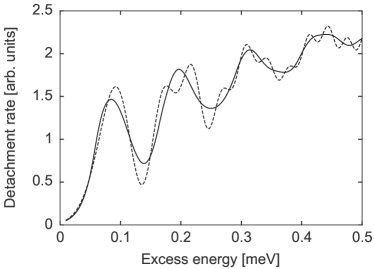
Much of the smooth appearance of the detachment rate in Fig. 2 is actually due to the averaging effect of a time-dependent electric field, as Fig. 3 demonstrates. The integration over the phase angle of the external electric field (9) effectively obliterates the oscillations in the photocurrent caused by self-interference of the emitted electron wave (Section I). In fact, a comparison of the effective rate (9) for the parallel field V/cm with the detachment cross section (8) in a constant parallel field with equal rms value ( V/cm) shows coinciding overall structure, while the numerous small-scale variations seen in the constant field curve are missing in the averaged rate.
II.4 Influence of magnetic substructure
Unfortunately it is not possible to measure the (averaged) total current depicted in Figs. 1–3 directly. The magnetic field causes Zeeman splitting of the magnetic sublevels of the ion and atom, and consequently several transitions closely spaced in energy contribute simultaneously to the photodetachment spectrum. Here, we analyze the situation encountered for the sulfur ions used in the experiment, where the transition between the fine structure components of the ion and of the emerging neutral atom was observed near the threshold at eV Blumberg et al. (1978, 1979).
Denoting the initial states of the ion by , and the final states of the atom and the detached electron by and respectively, the relative frequency shifts of the individual thresholds as compared to the field-free case:
| (15) |
depend on the Lande –factor of the atomic entities which e. g. reads for the ion:
| (16) |
where is the –factor of a free electron. The relative weight (3) of the various transitions is proportional to the dipole matrix element between the initial and final states; its calculation is a considerably more complicated task that involves addition of the angular momenta of the ion, atom, photon, and electron Edmonds (1957). The final result can be expressed in terms of Wigner - and –symbols Blumberg et al. (1979). Here, we are merely interested in the dependence of on the magnetic quantum numbers for perpendicular or –polarization of the laser beam. In this case,
| (17) |
with being a constant weight parameter. (The sign in the –symbol should be chosen as to produce a non-vanishing result.) The selection rules and enforced in (17) leave twelve possible transitions grouped into two sextets. Their details are given in Table 1. (If the restriction to –polarization is lifted, additional transitions with take place.) The total cross section for an ion in the initial magnetic state then is obtained by summation over all possible detachment channels:
| (18) | |||||
As these transitions possess weight factors of comparable size, details of the detachment spectrum invariably are lost in the superposition of the individual currents (11).
| 3 | ||||
| 8 | ||||
| 9 | ||||
| 12 | ||||
| 12 | ||||
| 6 | ||||
| 6 | ||||
| 12 | ||||
| 12 | ||||
| 9 | ||||
| 8 | ||||
| 3 |
A final correction that is rather negligible here but becomes important for cooled ions concerns the temperature-dependent occupation probabilities of the initial ionic substates that, in thermal equilibrium, are given by the Boltzmann distribution:
| (19) |
Finally, the experimentally measured quantity is the ratio of the number of surviving ions after a period of illumination to the initial ion population in the trap rather than the cross section itself. Assuming a uniform detachment rate, we find from (18) after summing over all initial ionic states:
| (20) |
The comparison of the results from this expression with the actual experimental data is the subject of Section IV.
III EXPERIMENTAL TECHNIQUE
In the experiment we studied the effects of an external electric field by observing the depletion of an ion cloud stored in a Penning ion trap Blumberg et al. (1978, 1979). To facilitate comparison with the theory model, photodetachment data were acquired as a function of photon energy both with and without the external electric field. The ions were illuminated by a single-mode laser tuned to the detachment threshold.
The ions are created in the Penning trap by dissociative attachment to carbonyl sulfide (OCS) gas at a pressure of Torr, controlled by a variable leak. The trap’s magnetic field is held fixed at 1.0 Tesla. The experiment is performed with a trapped ensemble on the order of ions. A relative measure of the number of trapped ions is made by resonantly driving the ions’ axial motion with a radio frequency voltage of 188 kHz applied to the trap end caps. The image current induced on the ring electrode is detected at twice the driving frequency by a tuned antenna coil, and the resulting voltage is then amplified in a heterodyne detection scheme. The trap and its detection scheme provide a nearly noiseless integrator of the trapped ion population, with noise introduced only upon output of the signal Blumberg et al. (1978).
The ions are photodetached with light from a tunable laser. The laser system, shown in Fig. 4, consists of a standing-wave dye laser pumped by an gas laser. The
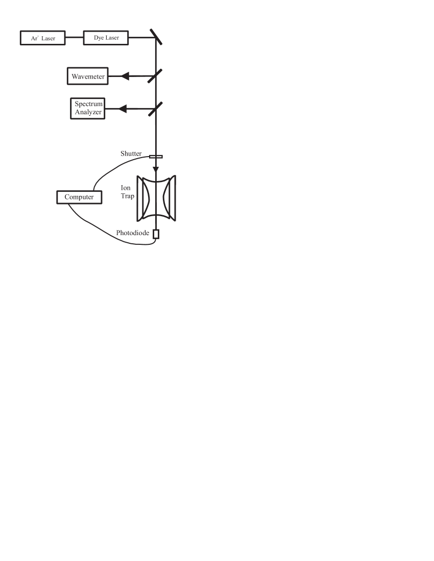
dye laser uses rhodamine 6G dye to produce roughly 100 mW at approximately 597 nm. The continuously tunable output oscillates on a single longitudinal mode. The laser output is measured by a travelling Michelson interferometer wavelength meter with a resolution of 0.02 Hall and Lee (1976). The laser mode is monitored by a Fabry-Perot spectrum analyzer with a 1500-MHz free spectral range. The laser beam is directed through the ion trap and the transmitted flux is recorded by a photodiode. A feedback signal from the photodiode to a mechanical shutter maintains constant integrated light intensity from cycle to cycle of the experiment.
The electric field is combined parallel to the trap’s magnetic field by adding a low radio frequency potential to the trap end caps. A typical frequency on the order of 1 MHz gives a field which is nearly static on the time scale of the photodetached electrons’ 36-picosecond cyclotron period. Of course, this electric field is not perfectly constant; thus a time average is calculated to quantify the field strength. The radio frequency is applied through a balun transformer which insures opposite polarity on the end caps. An electrostatic analysis of the trap’s hyperbolic electrodes shows that the applied field is linear throughout the trapping volume. The electrostatic analysis also gives a measure of the field strength, depending on the peak-to-peak applied radio frequency voltage.
One cycle of data acquisition consists of a background signal measurement by the ion detection electronics, followed by an ion creation period, an initial ion signal measurement, an optical interaction period, and a final ion signal measurement. The ion creation period typically lasts 8 seconds and the optical interaction typically lasts 500 ms. The ratio of the two ion signal measurements yields the fraction of ions surviving the interaction period. To account for trap losses by mechanisms other than detachment, alternate data cycles measure the trap retention ratio in the absence of laser light (shutter closed). Thus the ratio of the fraction of ions surviving the interaction period with and without light yields a fraction of ions surviving photodetachment, corrected to first order for background losses. The entire cycle is repeated both with and without the parallel electric field.
IV RESULTS AND ANALYSIS
In the experiment, data were acquired to determine the ratio of ions surviving detachment for photon energies near the threshold. Observations were made both with and without the external electric field parallel to the magnetic field. The magnetic field was held at T, and the peak applied radio frequency amplitude was V/cm, for a r. m. s. average of 9.9 V/cm. The radio frequency was 1.032 MHz, well above the trap eigenfrequency Foo . The single-mode laser beam was directed through the ion trap aligned perpendicular to the fields and with polarization, also perpendicular to the fields.
In Fig. 5 we show a comparison of the experimental and theoretical results [Eq. (20)] both with and without the external electric field. We plot the percentage of ions surviving detachment as a function of the excess photon energy above the electron affinity, expressed as a laser frequency detuning . The top frame of Fig. 5 shows a comparison for the magnetic field-only case (without the electric field). The bottom frame shows a comparison for the combined parallel fields case. To illustrate the effect of the added electric field, the bottom frame also shows the magnetic field-only theory curve. In each case the initial threshold and subsequent cyclotron structure are evident. As expected, due to the large number of possible transitions (Table 1) the degree of detail seen in Fig. 1 is not easily recognized. Fitting of the theory curve to the data was optimized with an ion cloud temperature of 2100 K and assuming an 8 rotation of the laser polarization away from purely polarization. Depending on the presence of the additional electric field, the structure of both the theory and experimental curves changes noticeably. For both the experiment and the theory,
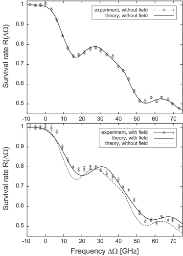
addition of the electric field diminishes the depth of modulation in the detachment ratio, particularly at the first dip above the initial threshold. This dip corresponds directly to the first peak in the relative detachment cross section shown in Fig. 1. We note in the bottom frame of Fig. 5 that a larger effect of the electric field is seen at the first dip for the experimental data than for the theory curve, and this difference is not well understood. However, the overall change in structure with the electric field is to be expected from our theoretical analysis (see Fig. 2), and is also qualitatively consistent with our semi-classical view of the detachment process: the external electric field pushes the electron away from the core as the electron orbits in the magnetic field. The result is a diminished overlap of the electron wave function with itself, yielding a reduced cross section. Furthermore, we observe that addition of the electric field shifts the minimum of the first dip in the detachment ratio to slightly higher energy, as predicted also by the theory. Unfortunately, not all details of the experimental results obtained for parallel fields could be reproduced by the theory.
Examination of the high precision achieved in experiments conducted with ion beams (see, for example, Ref. Gibson et al. (1993b, 2001)) might suggest that this work should be carried out in a beam apparatus. We considered this idea in depth, but found that combining all the necessary field components, along with particle detectors and optical access, was technically unfeasible. Alternately, the Penning ion trap’s size and geometric configuration lends itself ideally to superposition of the parallel fields. Furthermore, the trap’s typical storage time allows for lengthy optical interaction periods, and therefore greater precision in the photon energy.
Of course, the trapped ions always experience the velocity-dependent electric field perpendicular to the external magnetic field. To suppress its effects, efforts are currently underway to evaporatively cool the trapped ion cloud. Future experiments at lower ion temperatures are expected to yield greater contrast in the results with the addition of the parallel electric field. Also, detachment experiments with -polarized light (parallel to the fields) will minimize the number of allowed Zeeman transitions and should give a clearer picture of the underlying Green function. Another possible approach to diminish the number of Zeeman transitions is to quench the detachment from the lowest three Zeeman sublevels of the ion using a second laser. This will require attention to the possibility of collisional redistribution among the initial states, but again, this effect should be diminished with an evaporatively cooled ion cloud.
V CONCLUSIONS
We have investigated, theoretically and experimentally, near-threshold –wave photodetachment from atomic negative ions in parallel electric and magnetic fields. Our fully quantum mechanical theory based on the electron propagator allows us to calculate the transition rate in combined fields for a thermal ion cloud in a convenient manner, leaving only a single integral to be evaluated numerically. While showing agreement with previous theoretical work for detachment from in a purely magnetic field, the theory predicts both a loss of contrast in the detachment rate and a shift of the photocurrent maxima towards higher laser frequencies as a consequence of the additional electric field. We present experimental observations of photodetachment from in parallel fields that qualitatively agree with theoretical expectations. Future work will focus on similar experiments conducted with evaporatively cooled ions, where effects of the external electric field are expected to be more fully evident.
Acknowledgements.
We wish to acknowledge helpful conversations with D. J. Larson. This work was sponsored by the Research Corporation, Davidson College and the Deutsche Forschungsgemeinschaft (project number Kl 315/6-1). C. B. would like to thank the Alexander von Humboldt foundation and the Killam trust for financial support.References
- Manakov et al. (2000) N. L. Manakov, M. V. Frolov, A. F. Starace, and I. I. Fabrikant, J. Phys. B 33, R141 (2000).
- Blumberg et al. (1978) W. A. M. Blumberg, R. M. Jopson, and D. J. Larson, Phys. Rev. Lett. 40, 1320 (1978).
- Blumberg et al. (1979) W. A. M. Blumberg, W. M. Itano, and D. J. Larson, Phys. Rev. A 19, 139 (1979).
- Fabrikant (1981) I. I. Fabrikant, Sov. Phys. JETP 52, 1045 (1981), [Zh. Eksp. Teor. Fiz. 79, 2070–2077 (1980)].
- Demkov et al. (1982) Y. N. Demkov, V. D. Kondratovich, and V. N. Ostrovskii, JETP Lett. 34, 403 (1982), [Pis’ma Zh. Eksp. Teor. Fiz. 34, 425–427 (1981)].
- Stewart et al. (1988) J. E. Stewart, H. C. Bryant, P. G. Harris, A. H. Mohagheghi, J. B. Donahue, C. R. Quick, R. A. Reeder, V. Yuan, C. R. Hummer, W. W. Smith, et al., Phys. Rev. A 38, 5628 (1988).
- Baruch et al. (1990) M. C. Baruch, T. F. Gallagher, and D. J. Larson, Phys. Rev. Lett. 65, 1336 (1990).
- Baruch et al. (1992) M. C. Baruch, W. G. Sturrus, N. D. Gibson, and D. J. Larson, Phys. Rev. A 45, 2825 (1992).
- Gibson et al. (1993a) N. D. Gibson, B. J. Davies, and D. J. Larson, Phys. Rev. A 47, 1946 (1993a).
- Gibson et al. (1993b) N. D. Gibson, B. J. Davies, and D. J. Larson, Phys. Rev. A 48, 310 (1993b).
- Gibson et al. (2001) N. D. Gibson, M. D. Gasda, K. A. Moore, D. A. Zawistowski, and C. W. Walter, Phys. Rev. A 64, 061403(R) (2001).
- Du and Delos (1988a) M. L. Du and J. B. Delos, Phys. Rev. A 38, 1896 (1988a).
- Du and Delos (1988b) M. L. Du and J. B. Delos, Phys. Rev. A 38, 5609 (1988b).
- Fabrikant (1994) I. I. Fabrikant, J. Phys. B 27, 4545 (1994).
- Wong et al. (1988) H. Wong, A. R. P. Rau, and C. H. Greene, Phys. Rev. A 37, 2393 (1988).
- Rau and Wong (1988) A. R. P. Rau and H. Wong, Phys. Rev. A 37, 632 (1988).
- Krause (1990) H. F. Krause, Phys. Rev. Lett. 64, 1725 (1990).
- Bryant et al. (1987) H. C. Bryant, A. Mohagheghi, J. E. Stewart, J. B. Donahue, C. R. Quick, R. A. Reeder, V. Yuan, C. R. Hummer, W. W. Smith, S. Cohen, et al., Phys. Rev. Lett. 58, 2412 (1987).
- Fabrikant (1991) I. I. Fabrikant, Phys. Rev. A 43, 258 (1991).
- Wang and Starace (1997) Q. Wang and A. F. Starace, Phys. Rev. A 55, 815 (1997).
- Peters and Delos (1993a) A. D. Peters and J. B. Delos, Phys. Rev. A 47, 3020 (1993a).
- Peters and Delos (1993b) A. D. Peters and J. B. Delos, Phys. Rev. A 47, 3036 (1993b).
- Peters et al. (1994) A. D. Peters, C. Jaffe, and J. B. Delos, Phys. Rev. Lett. 73, 2825 (1994).
- Peters et al. (1997) A. D. Peters, C. Jaffe, and J. B. Delos, Phys. Rev. A 56, 331 (1997).
- Liu and Wang (1997a) Z. Y. Liu and D. H. Wang, Phys. Rev. A 55, 4605 (1997a).
- Liu and Wang (1997b) Z. Y. Liu and D. H. Wang, Phys. Rev. A 56, 2670 (1997b).
- Kramer et al. (2001) T. Kramer, C. Bracher, and M. Kleber, Europhys. Lett. 56, 471 (2001).
- Blondel et al. (1996) C. Blondel, C. Delsart, and F. Dulieu, Phys. Rev. Lett. 77, 3755 (1996).
- Blondel et al. (1999) C. Blondel, C. Delsart, F. Dulieu, and C. Valli, Eur. Phys. J. D 5, 207 (1999).
- Kramer et al. (2002) T. Kramer, C. Bracher, and M. Kleber, J. Phys. A 35, 8361 (2002).
- Bracher et al. (2003) C. Bracher, T. Kramer, and M. Kleber, Phys. Rev. A 67, 043601 (2003).
- Landau and Lifshitz (1991) L. D. Landau and E. M. Lifshitz, Quantum Mechanics: Non-relativistic Theory (Addison-Wesley, 1991).
- Reinhardt (1983) W. P. Reinhardt, J. Phys. B 16, L635 (1983).
- Du and Delos (1987) M. L. Du and J. B. Delos, Phys. Rev. Lett. 58, 1731 (1987).
- Du (1989) M. L. Du, Phys. Rev. A 40, 1330 (1989).
- Wang and Starace (1995) Q. Wang and A. F. Starace, Phys. Rev. A 51, 1260 (1995).
- Economou (1983) E. N. Economou, Green’s Functions in Quantum Physics (Springer, Berlin, 1983).
- Nieto (1992) L. M. Nieto, J. Math. Phys. 33, 3402 (1992).
- Jackson (1975) J. D. Jackson, Classical Electrodynamics (John Wiley and Sons, New York, 1975).
- (40) A simple calculation shows that the effective external field acting on the trapped ions is given by .
- Abramowitz and Stegun (1965) M. Abramowitz and I. A. Stegun, Handbook of Mathematical Functions (Dover, New York, 1965).
- Clark (1983) C. W. Clark, Phys. Rev. A 28, 83 (1983).
- Sadeghpour et al. (2000) H. R. Sadeghpour, J. L. Bohn, M. J. Cavagnero, B. D. Esry, I. I. Fabrikant, J. H. Macek, and A. R. P. Rau, J. Phys. B 33, R93 (2000).
- Greene (1987) C. H. Greene, Phys. Rev. A 36, 4236 (1987).
- Edmonds (1957) A. R. Edmonds, Angular Momentum in Quantum Mechanics (Princeton University Press, Princeton, 1957).
- Hall and Lee (1976) J. L. Hall and S. A. Lee, App. Phys. Lett. 29, 367 (1976).