Rotating Metal Band Target for Pion Production at Muon Colliders and Neutrino Factories
Abstract
A conceptual design is presented for a high power pion production target for muon colliders that is based on a rotating metal band. Three candidate materials are considered for the target band: Inconel alloy 718, titanium alloy 6Al-4V (grade 5) and nickel. A pulsed proton beam tangentially intercepts a chord of the target band that is inside a 20 tesla tapered solenoidal magnetic pion capture channel similar to designs previously considered for muon colliders and neutrino factories. The target band has a radius of 2.5 meters and is continuously rotated at approximately 1 m/s to carry heat away from the production region and into a water cooling tank. The mechanical layout and cooling setup of the target are described, including the procedure for the routine replacement of the target band. A rectangular band cross section is assumed, optionally with I-beam struts to enhance stiffness and minimize mechanical vibrations. Results are presented from realistic MARS Monte Carlo computer simulations of the pion yield and energy deposition in the target and from ANSYS finite element calculations for the corresponding shock heating stresses. The target scenario is predicted to perform satisfactorily and with conservative safety margins for multi-MW pulsed proton beams.
1 Introduction and Overview
| Property | Inconel 718 | Ti-alloy | nickel |
| target band radius, [m] | 2.5 | 2.5 | 2.5 |
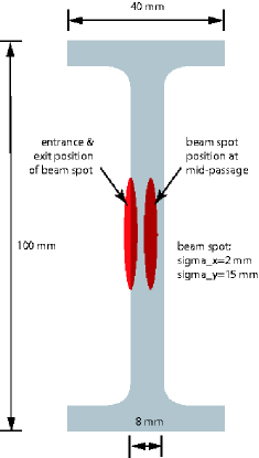
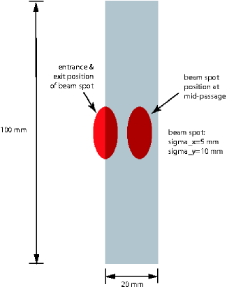
| band thickness, [mm] | 8 | 20 | 8 |
| band webbing height, [mm] | 100 | 100 | 100 |
| full width of band flanges, [mm] | 40 | – | 40 |
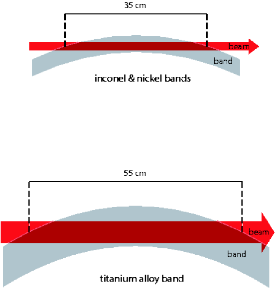
| beam path length in band, [cm] | 35 | 55 | 35 |
| proton interaction lengths () | 2.1 | 2.0 | 2.3 |
| weight of band, [kg] | 169 | 139 | 183 |
| horizontal beam-channel angle (), [mrad] | 100 | 100 | 100 |
| rms beam spot size at target (horizontal), [mm] | 2 | 5 | 2 |
| rms beam spot size at target (vertical), [mm] | 15 | 10 | 15 |
The design of a pion production target for a muon collider or neutrino factory is challenging because of the combination of high average power and large instantaneous energy depositions from the pulsed proton beam, the geometric constraints from the capture solenoid surrounding the target, and the desire to maximize the pion yield through use of transversely thin targets constructed from elements with high, or at least medium, atomic numbers.
Other target options that have previously been considered for either muon colliders or neutrino factories include liquid mercury jets [1, 2, 3] and a radiation cooled graphite rod [4]. This paper presents a solid-target option that is based on a rotating band geometry. Similar conceptual designs for rotating band targets have been presented previously [3, 5, 6, 7, 8].
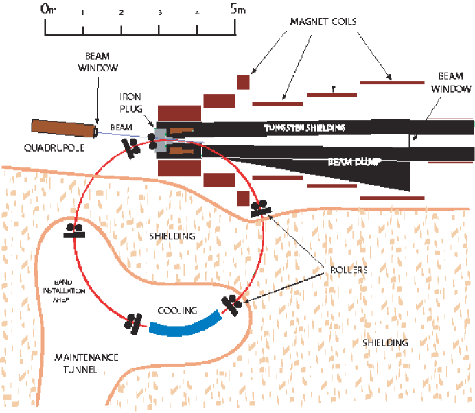
A plan view of the targetry setup for the band target option is shown in figure 1. A 2.5 meter radius circular target band threads through a solenoidal magnetic capture channel to tangentially intercept the proton beam. Three metals are considered as candidates for the target band: Inconel alloy 718, titanium alloy 6Al-4V grade 5 and pure nickel. The pion capture channel is a slight modification of a previously presented conceptual design [2, 3], as will be discussed further in section 6.
The proton beam enters the center of the target band webbing at a glancing angle, and the beam center traverses approximately two interaction lengths of target material before the surviving protons exit the target due to the curvature of the band. The cross sectional dimensions of the band and its orientation relative to the proton beam are shown in figures 2 and 3; the specifications of the band and the proton beam dimensions are enumerated in table 1. Inconel and nickel were studied for identical band dimensions and proton beam parameters, whereas the titanium alloy band was thicker, with no I-beam flanges required for stiffness, and used a larger proton beam spot. The circulating band is cooled by passage through a water tank located in a separate radiation-shielded maintenance enclosure.
The sections in this paper discuss, in order: 1) the range of expected proton beam parameters, 2) the properties of the candidate target materials and the specifications of the target band, 3) the drive and support rollers for the target band, 4) considerations for operating the target region in an air environment, 5) required modifications to the pion capture and decay channel in order to incorporate the rotating band, 6) cooling of the band in a water tank, 7) radiation damage and the replacement scheme for the target band, 8) MARS Monte Carlo simulations of pion yield and the beam energy deposition distribution, 9) beam-induced shock heating stresses on the target band, and 10) overall conclusions on the rotating band target design scenario.
2 Incident Proton Beam Specifications
Pion sources for muon colliders have similar requirements to those for the related technology of neutrino factories. However, there is a greater emphasis on high charge proton bunches because, for high luminosity muon collider parameters, the produced pion cloud must eventually be transformed into muon bunches containing at least muons per bunch at collision. This implies larger instantaneous stresses in the target.
In order to design for the most challenging shock stresses at muon colliders, the modeling for this paper is benchmarked to the largest proton bunch charge normally considered [2] at collision: muons per bunch; pion yield simulations for each target are first used to normalize the incident proton bunch charge to this capture rate. On working backwards to the number of pions and muons captured from the target, an assumed 25% survival rate [2] through the cooling channel and acceleration implies initially capturing a total of pions and muons, where the two charge signs have been summed.
As an aside, it is noted that this benchmarking procedure makes no assumption on whether or not the pion capture and decay channel is capable of capturing both charge signs in practice – a capability that seems plausible but has yet to be demonstrated in muon collider design studies – because the same proton bunch charge will be required in either case, and it is instead the bunch repetition rate that must be doubled if only one pion sign is collected at a time.
The bunch repetition rate is less critical than the proton bunch charge vis-a-vis instantaneous shock stresses because, as section 10 will show, the shock waves die down quickly enough for the bunches to be relatively independent in any reasonable muon collider bunch scenario.
For a given proton bunch charge, the additional specification of the bunch repetition rate determines the average proton beam power, some fraction of which will be deposited as heat in the target band and will need to be removed in the cooling tank. Proton beam powers of up to 7 MW [1] have been assumed for some muon collider scenarios; 4 MW is a commonly-assumed value [2]. Constraints on the muon beam currents from neutrino radiation may dictate less powerful proton drivers for many-TeV muon colliders. Design studies [4, 3] for neutrino factories have also assumed proton driver powers reaching the 1–4 MW level.
It will be seen in section 7 that the target cooling requirements are rather relaxed even for such proton beam powers. This is due to the band rotation spreading the heat load around the band circumference and to the large band surface area exposed to the cooling water. Therefore, the band target is unlikely in practice to set a limit on the average proton beam power.
Pion yield per proton is nearly proportional to proton energy, with lower proton energies slightly preferred in the multi-GeV energy range; equivalently, yield per MW of proton beam power falls slowly with increasing proton energy. As a competing concern, higher proton energies more easily enable the proton bunch lengths of 3 ns or less that are optimal for a capture and decay channel that provides efficient capture of the muons into rf acceleration while retaining substantial muon polarization. We consider two representative proton energies, 6 GeV and 24 GeV, in order to allow interpolation.
For the band target design discussed here, the proton beam is incident at a horizontal angle of 100 milliradians to the symmetry axis of the solenoidal magnet capture channel (to maximize the pion yield) and is focused to an elliptical beam spot at the target interaction region with assumed gaussian profiles in both transverse dimensions and with r.m.s. spot sizes tuned for acceptable shock heating stresses for the given proton beam parameters and band material. The stress and yield simulations assumed r.m.s. proton spot sizes of 2 mm (horizontal) and 15 mm (vertical) incident on the Inconel and nickel bands, and 5 mm (horizontal) by 10 mm (vertical) for the titanium alloy band.
3 The Target Band
| Property | Inconel | Ti-alloy | nickel |
| ave. atomic number, Z | 27.9 | 21.5 | 28.0 |
| ave. atomic weight, A | 59.6 | 46.8 | 58.7 |
| density (), [] | 8.19 | 4.43 | 8.88 |
| interaction length (), [cm] | 16.6 | 28.2 | 15.2 |
| radiation length (), [cm] | 1.55 | 3.56 | 1.48 |
| melting point, [oC] | 1298 | 1660 | 1450 |
| heat capacity, [] | 0.435 | 0.526 | 0.46 |
| thermal conduct., [] | 11.4 | 6.7 | 60.7 |
| electrical conduct., [] | 0.8 | 0.56 | 14 |
| expansion coeff. (), [] | 1.3 | 0.88 | 1.31 |
| elastic modulus (E), [] | 2.3 | 1.1 | 2.1 |
| 0.2% yield strength, [MPa] | 1100 [9] | [9, 11] | 59 [9] |
| fatigue strength [MPa], no. cycles | 480-620 at [12] | 510-700 at [9, 11] | N.A. |
The relevant properties of each of the 3 candidate target band materials – Inconel alloy 718, titanium alloy 6Al-4V grade 5 and nickel – are summarized in table 2.
Inconel 718 [9] is a niobium-modified nickel-chromium-iron superalloy that was developed for aerospace applications. Attractive properties include high strength, outstanding weldability, resistance to creep-rupture and resistance to corrosion from air and water. It is used in high radiation environments such as the core internals of light-water nuclear reactors; examples of applications at accelerators include high intensity proton beam windows and as the water-containment material for proton beam degraders. It was proposed for beam windows and for cladding the tungsten target elements in the 170 MW proton beam at the Accelerator Tritium Production (ATP) project (now part of the Advanced Accelerator Applications initiative) and is the back-up candidate (behind 316LN stainless steel) for the construction of Spallation Neutron Source (SNS) target components.
The elemental composition of Inconel alloy 718 that was used for pion yield calculations is [9] (with percentage by weight then molar fraction in the brackets): Ni (54.3%, 0.537), Cr (19.0%, 0.212), Fe (17.0%, 0.177), Nb (5.1%, 0.032), Mo (3.1%, 0.019), Ti (0.9%, 0.011), Al (0.6%, 0.013).
The titanium alloy under consideration is titanium 6Al-4V (Grade 5), consisting of titanium alloyed with 6% aluminum and 4% vanadium by weight. This high-strength alpha-beta alloy is among the most versatile and widely used of the titanium alloys. Applications include in pumps, valves, turbines, aerospace and automotive parts, and vessels and casings where corrosion is an issue. It offers ready machinability and, unlike some alpha-beta titanium alloys, is not greatly embrittled by welding. Titanium and titanium alloys have been used in production targets, and this particular alloy was recommended [10] after use in beam windows at CERN.
Table 2 shows nickel to have by far the lowest yield strength and fatigue strength of the three material options. However, nickel targets seem to evade these low-strength predictions, with successful operation in high power pulsed proton beams. For example, the currently operating nickel target [13] at the Fermilab antiproton source has absorbed peak energy depositions of up to 600 J/g over 2.4 microseconds, corresponding to an impressive temperature rise. It has been speculated that such nickel targets survive because they can self-anneal in high power target environments, although the actual reason for their exceptional performance is not well understood.
As a concern for nickel targets, it was the experience of both the FNAL anti-proton target [13] and BNL g-2 nickel target [14, 15] that the nickel surfaces slowly deteriorated and eventually began to powder on timespans of order one year. The implications of this for the target replacement lifetime and possible radioactive contamination would need to be addressed for a muon collider target scenario. Also, its much higher electrical conductivity will cause greater drag on the target band from magnetic eddy currents in the capture magnet. On the other hand, it will be seen that nickel’s pion yield is predicted to be slightly better than Inconel and significantly better than titanium alloy, so it may well be an attractive option for muon collider scenarios with low repetition rate proton beam parameters where the beam-induced damage will be minimized or eliminated and the band can be rotated more slowly to reduce the magnetic eddy currents.
The requirements for a tightly focussed proton beam spot on the target are more relaxed than, e.g., for an anti-proton production target because any contribution from the spot size to the produced pion beam emittance will tend to get washed out when the pions decay to muons. The dimensions of the band webbing and proton beam spot were chosen to approximately maximize the pion yield while keeping the density of energy depositions in the target to an acceptably low level. General requirements for yield are that the proton path length through the target material should be [2, 16] approximately 1.5–2 nuclear interaction lengths, and that the band should be thin enough to allow most of the pions to escape the target. It is predicted [1, 16] that high atomic number (high-Z) or medium-Z elements are favored over low-Z elements for the higher end of the considered range of proton energies; this advantage is less marked at lower proton energies. Inconel, titanium alloy and nickel can all be considered to fall within the category of medium-Z materials.
Tilting targets by approximately 100 milliradians with respect to the capture solenoid has generally also been found [2, 16] to slightly increase the pion yield. The elliptical beam spot was chosen solely to reduce the beam-induced stress by spreading out the beam energy deposition within the target.
4 Target Band Drive and Support Mechanism
The target band rotates at of order 1 m/s, depending on the target material and proton beam parameters, and with a rotation sense away from the proton beam direction. Faster rotation minimizes heating pile-up from successive proton pulses but the mechanical drive power must increase as the square of the rotation velocity in order to compensate for eddy current drag in the 20 tesla solenoid.
As a numerical example of eddy current forces, it can be roughly estimated that several hundred watts of drive power would be required to overcome the eddy current forces from an Inconel band with the given cross-section and rotating at 1 m/s. According to the ratio of electrical conductivities in table 2, the eddy current power for this scenario would be be times worse if a nickel band was used instead of Inconel.
The band is guided and driven by several sets of rollers located around its circumference, as is shown in figure 1. The motive power is most conveniently applied from those rollers within the maintenance tunnel, where the radiation environment is less severe and maintenance is easier. For most proton beam parameters, the eddy current drag will not be large enough to require toothing the rollers and the parts of the band they contact. The tightest position tolerances on the rollers are the precisions of 1 mm or better required for the rollers defining the band’s horizontal position at interaction with the beam.
Following the design of the BNL g-minus-2 target [14], the roller assemblies will all incorporate self-lubricating graphalloy [17] bushings. These commercially available bushings are manufactured from molded graphite impregnated with metal and, in contrast to oil-based lubricants, are compatible with high radiation environments.
5 Considerations for Targetry in an Air Environment
The pion production region of the target is in an air environment. This simplifies target maintenance and target band replacement by avoiding any requirement to break and re-establish seals in a high radiation environment.
The vacuum window for the proton beam-line is located immediately downstream from the final quadrupole magnet and a few meters upstream from the production region. The proton beam spot size at this beam window will be much larger than for the focused beam at the target interaction region; this minimizes the peak beam-heating stresses and radiation damage in the window and also simplifies the window cooling. The vacuum in the pion decay channel begins at a beam window located (e.g.) 6 meters downstream from the target interaction region. These distances are not expected to result in either excessive proton-air interactions upstream from the target or significant degradation of the pion yield since each meter of air corresponds to only 0.13 of matter, 0.14% of an interaction length, 0.33% of a radiation length and to a minimum-ionizing energy loss of only 0.24 MeV.
Following the procedure adopted for the BNL g-minus-2 target [14], activated air and gases from the target and interaction region are continuously diluted and vented from the target hall into the outside atmosphere. Initially, a loosely airtight container around the target impedes gas transport away from the target until most short-lived radio-isotopes have decayed. The iron plug shown in figure 1 may suffice for this purpose. The activated air is then transported along the target hall to allow dilution by mixing with unactivated air until acceptable activation levels are reached for venting into the outside atmosphere.
6 The Pion Capture and Decay Channel
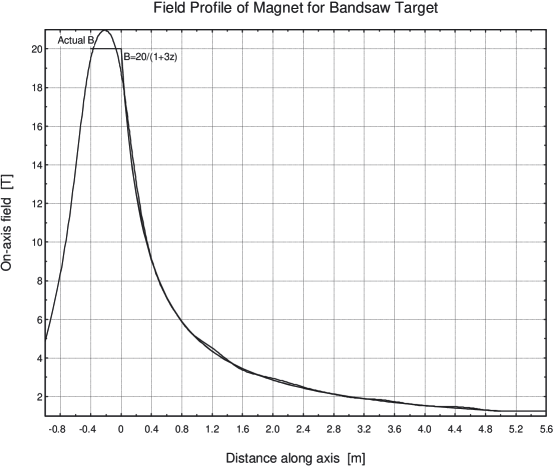
The pion capture channel in figure 1 represents only a slight variation on channels considered previously [2, 4, 3]. The magnetic field in the solenoidal capture channel is nearly identical to that in previous studies. As a minor change, no requirement remains for field homogeneity upstream from the production region, so no there is no constraint on how the upstream field rises to the 20 tesla maximum. On the other hand, the third coil block downstream from the upstream end had to be moved outwards by approximately 10 centimeters to provide adequate space for the band to exit the channel. A modest re-optimization of the coil currents was required to restore the magnetic field map in this region to the specifications of the previous studies. The coil block positions and dimensions shown in figure 1 are taken directly from the computer programs used to optimize the magnet geometry and magnetic field profile. The re-optimized magnetic field map is shown in figure 4.
The other requirement on the capture and decay channel that is additional to previous scenarios is the provision of entry and exit ports for the target band. The design of these ports is simplified by the air environment of the pion production region. The entry port need only traverse the iron plug in the upstream end of the capture solenoid. The downstream port is more challenging since it must traverse the tungsten-based radiation shielding and then pass between the solenoidal magnet coil blocks and out of the pion decay channel.
If it is considered undesirable to incorporate such an exit port into a single cryostat, then the alternative option exists of breaking the cryostat longitudinally into two cryostats, so that the band can exit between them. The exit port likely will require some cladding with, e.g., tungsten carbide and water, in order to shield the magnet coils from any additional radiation load from low-energy neutrons.
7 Target Cooling
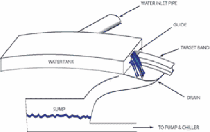
The heated portion of the band rotates through a 2 meter long cooling tank whose conceptual design is shown in Fig. 5.
The water flows due to the gravitational head in a feeder tank, with the band entrance and exit ports in the ends of the tank also serving as the water outlets. The flow rate can be simply adjusted by varying the head in the feeder tank. Guides in the ports steer the water off to the side of the target band and into a drain, to then be pumped through a chiller and recirculated. The drains and structure at the ends of the tank will be covered with hoods to prevent splashing (not shown in figure 5) and, at the end where the band exits, high pressure air will blow the residual water off the wetted band as it exits the hood.
For equilibrium, the heat removed must balance the fraction of the proton beam power deposited as heat in the band, which MARS Monte Carlo computer simulations found to be approximately 7% (see section 9), i.e., approximately 70 kW of heat deposited in the target band per megawatt of beam power.
The 2 meter length of water in the cooling tank was chosen to be sufficient to obviate the need for forced convection of the cooling water for proton beam powers up to several MW, while many-MW proton beam powers could be contemplated by incorporating forced convection and/or increasing the cooling tank length. For the example of the I-beam cross section for Inconel or nickel, the 0.69 square meters of immersed target band surface area corresponds to an average heat transfer rate of 10 per megawatt of beam power. Even for proton beam powers up to several megawatts, this will be comfortably below the 100 approximate maximum sustainable rate for cooling by nucleate-boiling with standing water under favorable conditions. The cross section of the titanium band is 70% as large, so the heat transfer rates would need to be about 40% higher.
The water flow rate parameters are also relatively modest. For example, an assumed 5 degree centigrade average temperature rise in the water would require an exit flow rate of about 3.3 liters per second per megawatt of incident beam power. In the approximation that viscosity is neglected, this flow rate could be met by a combination of 1) a 2 m/s flow velocity supplied by pressure from a 20 cm head of water and 2) an 18 cross-sectional area per megawatt of beam power in each of the 2 exit ports around the cross section of the target band.
Concerning the desirability of drying the target between its multiple passages through the cooling tank and subsequent exposures to the beam, it is noted that this was not considered necessary for the BNL g-2 rotating-disk production target [14], which was simply left wet. However, the motivation for air-drying is stronger for the geometry, drive mechanism and larger local temperature rises of the rotating band target considered here, and so it is assumed that drying air jets are included in the design. As well as drying the bulk surface area, it should be relatively straightforward to shape the air flow to also remove all or almost all the water from the transverse gaps between the 8 circumferential sections of the band and from the 3 circumferential stress-barrier grooves at both the top and bottom of the webbing.
As an attractive feature for maintenance, all equipment for the cooling loop that requires moving parts – the pumps, chiller, valves for the feeder tank, and air compressor – can be conveniently located either inside the maintenance tunnel or entirely outside the shielding walls surrounding the target hall.
8 Radiation Damage and Target Band Replacement
The rotation of the target band has the desirable dilution effect that the rate of radiation damage on any particular section of the band material is reduced by roughly two orders of magnitude relative to a fixed target geometry, because the region of maximum energy deposition from any particular proton bunch has a characteristic width on the order of one interaction length (i.e. 15–28 cm), whereas the 15.7 meter band circumference corresponds to 55–100 interaction lengths, depending on the target material. Even so, the strength and other mechanical properties of the target band will likely eventually be degraded by repeated shock heating stresses and radiation damage to the point where the band needs to be replaced. Therefore, the target design must allow for the routine removal and replacement of the target band.
A very approximate determination of radiation damage to the target band can be obtained from the estimated fluence of particles through the target material and the rule-of-thumb that 1 displacement per atom (dpa) will be produced by a fluence minimum ionizing particles per square centimeter. This predicts that a few-MW proton beam would produce of order 1 displacement per atom (dpa) per year of radiation damage. In turn, this suggests that annual replacement of the band should easily suffice even for the highest power proton beams under consideration since, for comparison, a 6 dpa design lifetime has been set for the 316LN steel (or Inconel 718, as a back-up) target components in the SNS.
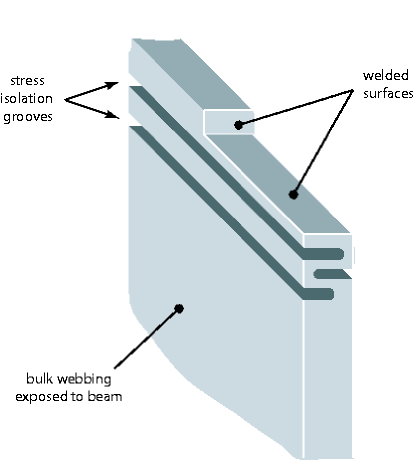
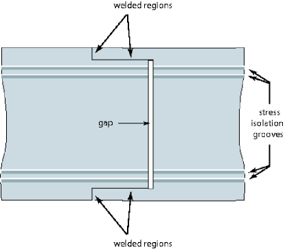
Welds can be a potential Achilles heel for high-stress targetry applications. Favorable features for the rotating band target geometry in this regard are that no welds are required between dissimilar metals and that the welds can be placed at the top and bottom of the band webbing, away from the mid-height region that receives the beam energy. For further protection, circumferential grooves placed inside the welds can mechanically isolate them from shock waves emanating from the beam interactions. A welding scenario incorporating such grooves is shown in figure 6.
With three grooves inside each weld, as shown in figure 6, the shock waves emanating from the target region will be almost entirely reflected back into the central region or else dissipated by multiple scatters. This will effectively shield the weld from the shock-heating transients.
Because the band is not load-bearing, each of the grooves can extend nearly through the thickness of the webbing, and they are assumed to run all the way around the band circumference. The removal of material away from the mid-height production region should be irrelevant, or perhaps even slightly beneficial, to the pion yield.
The join region can be blown dry after exiting the cooling tank. A few-millimeter gap might well be retained in the joins between the 8 circumferential band segments, in order to avoid leaving small cracks that could retain water by capillary action after passage through the cooling tank. Such gaps will have a negligible effect on the pion yield for those proton pulses passing through the join regions, since they represent only of order a one percent reduction in the effective target length. The yield is insensitive to such small changes near the optimal beam intersection length because, by definition, the optimal beam intersection length for yield occurs where the first derivative of yield with respect to length is zero.
Each of the candidate band materials is suitable for welding. Inconel 718 gives outstanding weldability [9] and resistance to post-weld cracking. Ti-6Al-4V is among the better alpha-beta titanium alloys for welding [19] and is weldable in the annealed condition as well as in the solution-treated and partially-aged conditions.
Target bands will be installed and extracted from the dedicated band maintenance area located in the maintenance tunnel (see figure 1). Remote extraction is presumably the only viable option for heavily irradiated used bands. The band will be removed from its channel by progressively clamping and then shearing off (e.g.) 1 meter lengths and dropping them into a hot box. It is expected that, once the hot box has been locked shut and the irradiated band removed to a disposal area, radiation levels in the maintenance tunnel will have fallen to an acceptably low level to allow the immediate manual installation of the new band without the need for a cool-down period. This assumption should eventually be checked using particle tracking simulations (e.g. with MARS [20]) that can determine the level of residual radiation carried into the maintenance area by the target band and by neutrons leaking through the band ports in the shielding wall, although these levels are expected to be similar to those calculated in reference [18].
In what is almost the reverse procedure to band removal, the new band will be progressively welded together in situ from (e.g.) eight 1.96 meter long chords of target band that have been previously formed into the correct cross section and circumferential curvature.
9 MARS Monte Carlo Simulations of Pion Yield and Beam Energy Deposition
| band material | Inconel 718 | Ti-alloy | nickel | |||
|---|---|---|---|---|---|---|
| proton energy [GeV] | 6 | 24 | 6 | 24 | 6 | 24 |
| captured yield/proton | 0.102 | 0.303 | 0.080 | 0.249 | 0.102 | 0.302 |
| captured yield/proton | 0.105 | 0.273 | 0.083 | 0.224 | 0.105 | 0.292 |
| 15.5 | 5.56 | 19.6 | 6.78 | 15.5 | 5.39 | |
| 149 | 214 | 188 | 260 | 149 | 207 | |
| [J/g] | 32.0 | 31.7 | 25.6 | 21.3 | 32.5 | 37.4 |
| [] | 74 | 73 | 49 | 40 | 71 | 81 |
| stress, [MPa] | 330 | 360 | 72 | 68 | 330 | 340 |
| % of fatigue strength | 53-69% | 58-75% | 10-14% | 10-13% | N.A. | N.A. |
Full MARS [20] tracking and showering Monte Carlo simulations were conducted for 6 GeV and 24 GeV protons incident on the target, returning predictions for the pion yield and energy deposition densities.
The detailed level of the MARS simulations is illustrated by figure 7, using the example of several 24 GeV proton interactions in an Inconel band. Figure 8 shows the corresponding yield and momentum spectra for all hadrons; figure 9 gives more detailed information for the pions. Several scatter plots to illustrate the distribution in phase space of the produced pions are displayed in figure 10. The plots are seen to be relatively symmetric in the x and y coordinates, which indicates that any asymmetries due to the band tilt and elliptical beam spot are largely washed out by the large phase space volume occupied by the produced pions.
The yield per proton for positive and negative pions-plus-kaons-plus-muons at 70 cm downstream from the central intersection of the beam with the target was predicted for the kinetic energy range 32232 MeV that approximates the capture acceptance of the entire cooling channel. Note that the material in the flanges of the I-beam for the Inconel and nickel targets was not included in the calculation; its inclusion might result in a small change in the predicted yield.
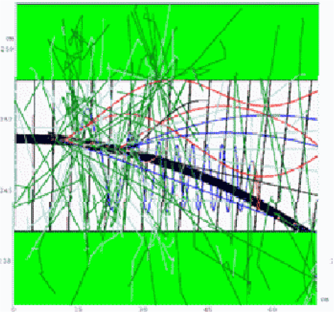
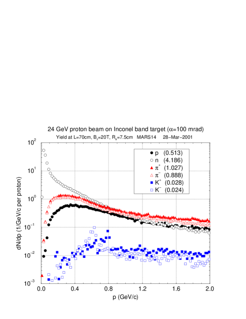
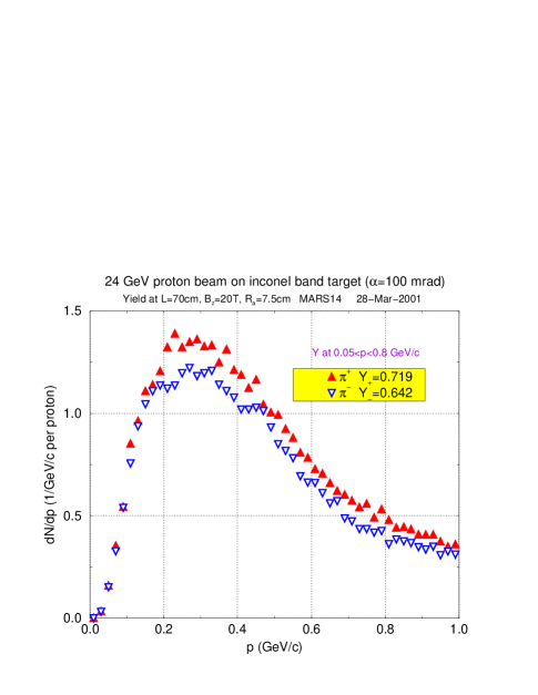
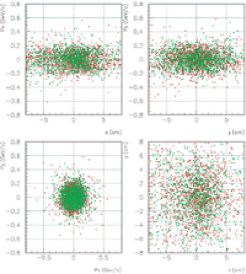
Table 3 summarizes the yield and energy deposition results from the MARS calculations. It includes the several rows of derived results that assume the scenario, taken from section 2, of captured pions. These derived quantities are identified with a superscript “3.2” and include: the required number of protons per pulse, , the required total proton pulse energy, , the maximum localized energy deposition in the target material and corresponding temperature rise, and .
Approximately 7% of the proton beam energy is deposited in the target. Detailed 3-dimensional maps of energy deposition densities were generated for input to the dynamic target stress calculations that are discussed in the following section.
10 Shock Heating Stresses
Probably the most critical issue faced in solid-target design scenarios for pion production at neutrino factories or muon colliders is the survivability and long-term structural integrity of solid targets in the face of repeated shock heating. To investigate this, finite element computer simulations of the shock heating stresses have been conducted using ANSYS, a commercial package that is widely used for stress and thermal calculations.
The target band geometry was discretised into a 3-dimensional mesh containing approximately 30 000 elements. This was as fine as the computing capacity and memory allowed and was judged to be adequate for the accurate modeling of shock wave propagation.
The ANSYS simulations conservatively assumed that the deposited energy is all converted to an instantaneous local temperature rise. The dynamic stress analyses were preceded by a transient thermal analysis to generate temperature profiles using as input the 3-dimensional energy deposition profiles previously generated by MARS for the production assumption of total captured pions (see the preceding section).
Dynamic stress calculations were then performed both for a “free edge” band, i.e., with no I-beam flanges, and with a “fixed edge” constraint, in which the edges of the band are constrained against displacement in both the radial and axial direction. The “free edge” boundary condition is appropriate for the titanium alloy band; the “fixed edge” model is considered likely to provide an improved approximation to the Inconel and nickel bands with their I-beam flanges without requiring the extra computing capacity that would be needed to simulate the more complicated true geometry.
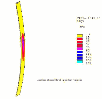
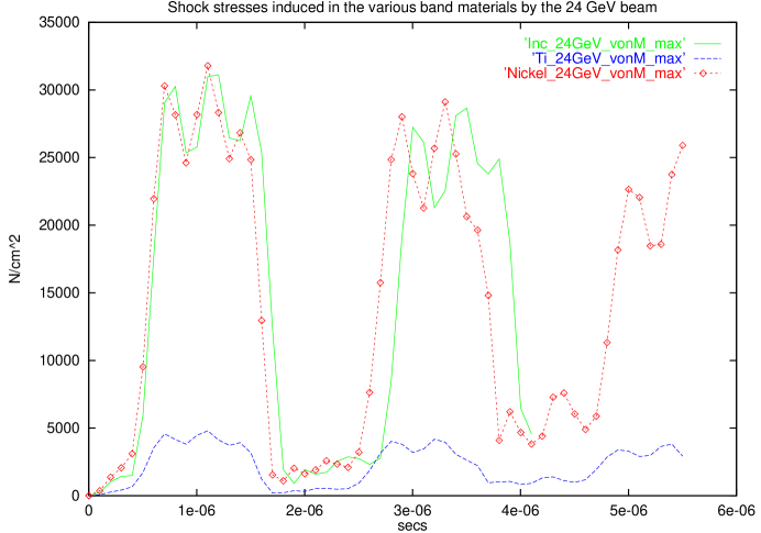
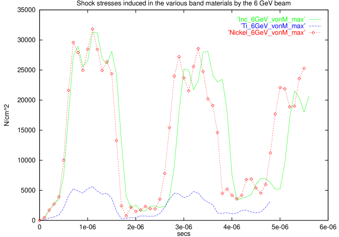
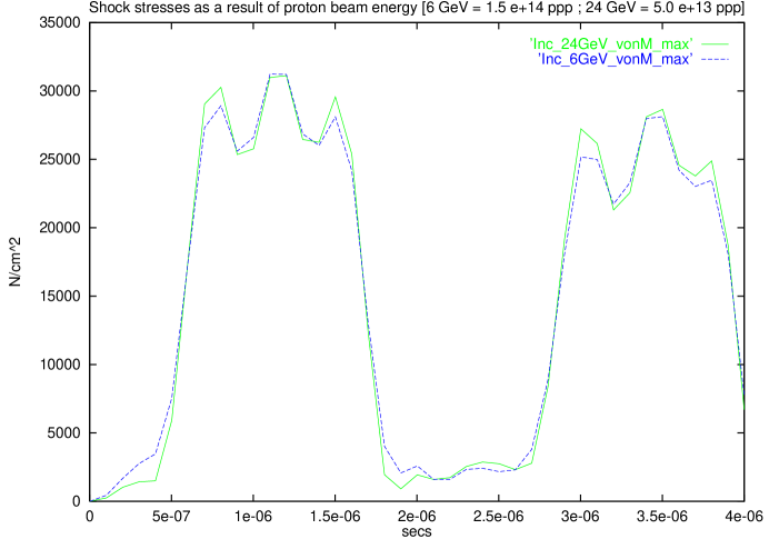
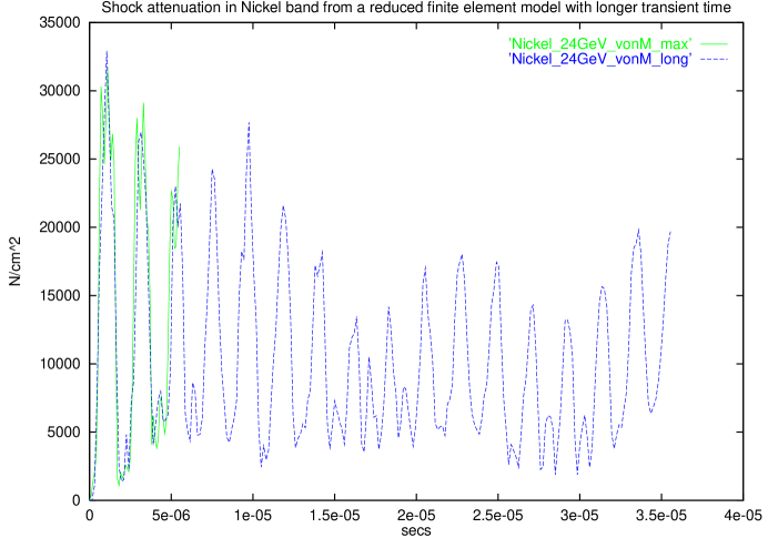
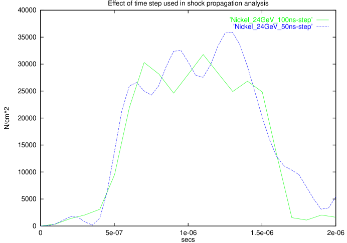
The von Mises stress (i.e., the deviation from the hydrostatic state of stress) was found to be initially zero but to develop and fluctuate over time as the directional stresses relax or are reflected from material boundaries. Figure 11 gives an example snapshot of the predicted von Mises stress distribution at one microsecond after the arrival of a proton pulse, and the remaining figures 12 to 16 show various aspects of the predicted stress at the position of maximum stress, respectively: the time development for 6 GeV protons and for all three band material candidates; the same for 24 GeV protons; superimposed plots for 6 GeV and 24 GeV protons and for the nickel band; the stress development over a long enough time-span to see the attenuation of the stress levels; and a check on the time step used in the ANSYS calculations.
Table 3 summarizes the ANSYS predictions for the maximum stress created at any time and any position in each of the band materials, . These values were obtained by reading off from figures 12 and 13 and then scaling to the bunch charge for a total yield of captured pions. The final row of table 3 displays the percentage of the fatigue strength (from table 2) that this represents.
For the Inconel band, the calculated fraction of the fatigue strength that the band would be exposed to in this “worst case” proton bunch scenario, 53-69%, is either close to or slightly above what could be considered a safe operating margin for the target band. A more definitive determination of the proton beam parameters that allow survivability and adequate safety margins for this target scenario could be provided by data from the ongoing BNL E951 targetry experiment [21], with planned stress tests for bunched 24 GeV proton beams incident on several types of targets, including Inconel 718. The Inconel target may well be appropriate for some proton beam specifications at a muon collider, and it has already been shown [3] to likely give a wide safety margin for the more relaxed beam parameters of neutrino factories.
The titanium alloy was predicted to have a very conservative safety margin even for the assumed muon collider beam parameters: only 10-14% of the fatigue strength. Although the yield is about 20% lower than for the other two candidate materials, target bands from titanium alloys look likely to survive with any proton bunch charges that might reasonably be contemplated for muon colliders.
Finally, nickel targets are known to evade the predictions for fatigue strength limits, as already mentioned. Test beam experiments would be required to establish the suitability or otherwise of a nickel band production target for any particular muon collider scenario.
All of the above calculations apply for a circumferentially continuous band. It remains to check the level of von Mises stresses at the gaps between the eight welded band sections, although it is noted that the BNL g-2 target was deliberately segmented longitudinally in order to reduce the beam stresses. For rotating band targets in muon colliders, additional periodic slots in the webbing may also be considered for thermal stress relief and eddy current reduction in rotating band targets for muon colliders.
11 Conclusions
In summary, the Inconel rotating band target design appears to be a promising option for pion production targets at muon colliders. The design concept appears to be manageable from an engineering point of view, and initial simulations of target yields and stresses are encouraging for each of three candidate target materials: Inconel 718, titanium alloy 6Al-4V grade 5 and nickel.
Priorities for further evaluation of this target scenario include engineering designs of the components, optimization of the band geometry for pion yield and calibration of the target stress predictions to experimental targetry results.
12 Acknowledgements
We acknowledge helpful discussions with Charles Finfrock, George Greene and Charles Pearson, all of BNL. This work was performed under the auspices of the U.S. Department of Energy under contract no. DE-AC02-98CH10886.
References
- [1] The Muon Collider Collaboration, Collider: A Feasibility Study, BNL-52503, Fermilab-Conf-96/092, LBNL-38946, July 1996.
- [2] The Muon Collider Collaboration, Status of Muon Collider Research and Development and Future Plans, Phys. Rev. ST Accel. Beams 2, 081001, 3 August, 1999.
-
[3]
Report from the Neutrino Factory and Muon Collider
Collaboration Feasibility study II,
http://www.cap.bnl.gov/mumu/studyii. -
[4]
FNAL Feasibility Study on a Neutrino Source Based on a
Muon Storage Ring,
http://www.fnal.gov/projects/muon_collider/nu-factory/. - [5] A Cupronickel Rotating Band Pion Production Target for Muon Colliders, B.J. King et al., Proc. PAC’99, IEEE, pp. 3041-3.
- [6] Rotating Band Pion Production Targets for Muon Colliders and Neutrino Factories, B.J. King, NIM A 451 (2000) pp. 335-343, Proc. ICFA/ECFA Workshop “Neutrino Factories based on Muon Storage Rings (nuFACT’99)”, physics/0005007.
- [7] Some thoughts on a high-power, radiation cooled, rotating toroidal target for neutrino production, J.R.J. Bennett, NIM A 451 (2000) pp. 344-348, Proc. ICFA/ECFA Workshop “Neutrino Factories based on Muon Storage Rings (nuFACT’99)”.
-
[8]
A Rotating Band Target for Pion Production at a Neutrino
Factory, using Study II Parameters,
B.J. King, N.V. Mokhov, N. Simos, R.J. Weggel,
Muon Collider Note 199,
http://www-mucool.fnal.gov/notes/notes.html. - [9] The elemental composition and other properties of Inconel 718 can be found at http://www.matweb.com .
- [10] Private communication with Peter Sievers (CERN).
-
[11]
Trans World Alloys,
http://www.twalloys.com - [12] Huntington Alloys - Inconel Alloy 718, 1978.
- [13] S. O’Day et al., “New Target Results from the FNAL Antiproton Source”, Proc. IEEE 1993 PAC 4, 3096.
- [14] ”The BNL Muon Storage Ring Beamline”, BNL g-2 Collaboration. Paper in preparation for submission to NIM.
- [15] Private communication with C. Pearson (BNL).
- [16] Particle Production for a Muon Storage Ring: I. Targetry and Yield, N.V. Mokhov, Nucl. Instr. Meth. in Phys. Research, A472, 546 (2001), FERMILAB-Conf-00/208 (2000).
- [17] Graphalloys are manufactured from molded graphite impregnated with metal. Graphalloy is a registered trademark of the Graphite Metallizing Corporation.
- [18] N.V. Mokhov, Particle Production and Radiation Environment at a Neutrino Factory Target Station, Fermilab-Conf-01/134 (2001). Paper submitted to the PAC2001 Conference, Chicago, IL.
-
[19]
Inox Company,
http://www.inox.co. - [20] N.V. Mokhov, ”The MARS Code System User’s Guide”, Fermilab-FN-628 (1995). N.V. Mokhov and O.E. Krivosheev, ”MARS Code Status”, Fermilab-Conf-00/181 (2000). http://www-ap.fnal.gov/MARS/ .
- [21] Alessi et al., “An R & D Program for Targetry and Capture at a Muon-Collider Source - A Proposal to the BNL AGS Division”.