SLAC–PUB–9254
June 2002
NLC Luminosity as a Function of Beam Parameters111Work supported by Department of Energy contract DE–AC03–76SF00515.
Y. Nosochkov, P. Raimondi, T.O. Raubenheimer, A. Seryi
Stanford Linear Accelerator Center, Stanford University,
Stanford, CA 94309
Abstract
Realistic calculation of NLC luminosity has been performed using particle tracking in DIMAD and beam-beam simulations in GUINEA-PIG code for various values of beam emittance, energy and beta functions at the Interaction Point (IP). Results of the simulations are compared with analytic luminosity calculations. The optimum range of IP beta functions for high luminosity was identified.
Presented at the 8th European Particle Accelerator Conference
(EPAC 2002)
Paris, France, June 3–7, 2002
NLC LUMINOSITY AS A FUNCTION OF BEAM PARAMETERS ††thanks: Work supported by Department of Energy contract DE–AC03–76SF00515.
Abstract
Realistic calculation of NLC luminosity has been performed using particle tracking in DIMAD and beam-beam simulations in GUINEA-PIG code for various values of beam emittance, energy and beta functions at the Interaction Point (IP). Results of the simulations are compared with analytic luminosity calculations. The optimum range of IP beta functions for high luminosity was identified.
1 INTRODUCTION
Maximizing luminosity is an important part of the NLC design optimization. Luminosity for the head-on symmetric gaussian beam collisions is given by [1]
| (1) |
where , , , and are, respectively, the number of bunches per train, number of particles per bunch, repetition rate, rms beam size at IP, and luminosity enhancement factor due to pinch and hourglass effects [1]. For zero IP dispersion, the beam size is , where and are the beam emittance and beta function at IP.
For optimization of luminosity it is desirable to analyze it as a function of beam parameters such as and incoming beam emittance . The use of analytical formula (1) requires accurate estimate of the final beam emittance and enhancement factor . However, analytical calculation of emittance dilution is complicated by the combined effect of high order chromaticity, non-linear fields in the Final Focus (FF) system and synchrotron radiation. Similarly, accuracy of the empirical formula for luminosity enhancement factor [1] has limitations as well.
For a more accurate and realistic computation of luminosity, we performed numerical tracking and beam-beam simulations using DIMAD [2] and GUINEA-PIG [3] codes. An automatic routine based on FFADA [4] was used to generate and track particles in DIMAD and then use the resultant distribution at IP for beam-beam simulation in GUINEA-PIG. Below we present results of these simulations, compare them with analytical calculations, and examine the optimum range for IP beta functions.
2 SIMULATIONS
The typical simulation in DIMAD and GUINEA-PIG included 20,000 particles per beam with the initial gaussian distribution in phase space, except for the energy spread where an appropriate double-horned distribution was used. Particles were tracked through the last 1433.8 meters of the NLC beamline which includes the final collimation section and the FF system as shown in Fig. 1 [5]. The ideal lattice without magnet errors was used, and the incoming beam distribution was matched to the initial machine phase ellipse. The following “nominal” set of the NLC parameters for 250 GeV beams was used in the calculations: , , Hz, [ m], mm, and mm, where and are the normalized emittance and rms bunch length of the incoming beam, respectively. Emittance growth due to synchrotron radiation in bends and quadrupoles was included in the DIMAD tracking, and head-on collisions were assumed for luminosity calculation.
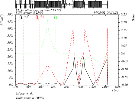
The NLC FF optics includes a non-linear correction system of sextupoles, octupoles and decapoles for compensation of high order chromatic and geometric effects generated in the FF and collimation section [5]. Normally, this system is optimized for the nominal set of parameters. Variation of emittance, energy and beta functions changes the beam size and synchrotron radiation effects in the FF. As a result, an additional tuning of the non-linear correctors may be needed to maintain maximum luminosity. However, a complete optimization of this system is somewhat time consuming. For this reason, a different technique was employed in the simulations to optimize this compensation. In this method, a scaling factor was used to vary all bending angles in the FF dipoles and another factor to scale dipoles in the collimation section. Relationship between the two factors was fixed to keep the IP horizontal position unchanged. Horizontal dispersion was linearly changed by the scaling, but remained separately closed in the collimation and FF sections. Strengths of the non-linear correctors were scaled the opposite way to keep chromatic correction near optimum. This variation of corrector strengths allows optimization of the FF geometric aberrations. The peak luminosity found by optimizing the bend scale factor is denoted by .
2.1 Variation of and Emittance
Luminosity as a function of and initial normalized emittance was studied using the NLC FF design for 250 GeV beams with the nominal parameters listed above. Two methods for variation of were tested. In the first method, six matching quadrupoles located between the collimation section and FF were adjusted to provide a local optics change for a desired . This adjustment changes beta functions only in the FF system. As a result, the optimal relationship between the collimation and FF sections is changed which may reduce the effect of the non-linear compensation. In the second method, the FF quadrupoles were not changed, but the initial betatron functions at the beginning of collimation section were adjusted to provide a desired . This technique requires that the optics match is done upstream of the collimation section. In this method, beta functions change simultaneously in the collimation and FF sections and, therefore, transformation between the two sections is preserved which may be a better option for keeping the non-linear compensation at optimum. Another advantage of this approach is that the collimator settings would not need to be changed. Simulations showed that luminosity as a function of is about the same in both methods, but the second method delivered up to 7% higher luminosity at very low . In the following sections, only the results of the second method are presented.
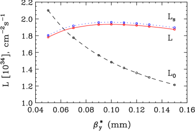
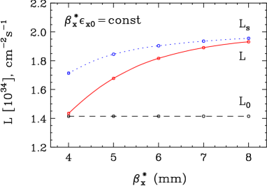
Luminosity versus and for 250 GeV beams is shown in Fig. 2, 3, where is obtained using tracking and beam-beam simulations, is enhanced by optimizing the bend scaling factor, and is the analytical luminosity without emittance growth and enhancement factor :
| (2) |
where . Note that in Fig. 2 and 3. Ratio quantifies the combined effect of luminosity enhancement factor and emittance growth in the collimation and FF optics.
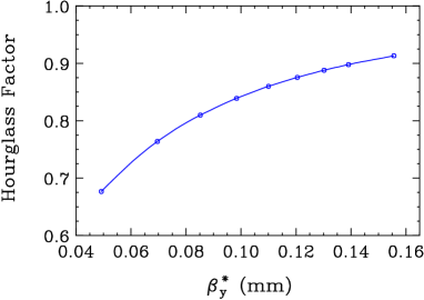
Fig. 2 shows rather weak dependence of versus with the maximum reached near mm, close to the nominal value of 0.11 mm. Luminosity is affected by the beta factor , emittance growth (due to synchrotron radiation and high order aberrations), hourglass reduction and pinch enhancement factors. At high values of , luminosity reduction is dominated by the beta factor, while at low , it is caused by combination of the hourglass factor, pinch effect and emittance growth which prevail over the stronger focusing. The hourglass factor calculated using analytical formula [6] for mm is shown in Fig. 4 as a function of . For symmetric flat beams it only depends on ratio of . For example, it reduces luminosity by 32% at mm compared to 14% at the nominal 0.11 mm. Emittance growth at low qualitatively may be explained by the increased beam size in the FF magnets () which enhances non-linear optical aberrations. Bend scaling increases luminosity () only by , but requires stronger bends in the FF.
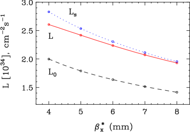
Luminosity versus is shown in Fig. 3, where the nominal is 8 mm. In this case, the hourglass factor is roughly constant. At low , luminosity is increased by the beta factor and to less extent by the pinch effect which prevail over reduction due to emittance growth. Up to 9% higher luminosity () can be achieved at low by scaling the FF bends by up to +57%. The scaling increases dispersion and reduces non-linear corrector strengths required for chromatic compensation. As a result, enhancement of geometric aberrations caused by larger beam size in the FF () is compensated by the reduction of the sextupole and other corrector strengths.
Fig. 5 shows luminosity versus , where is kept constant. The first order beam size at IP and are constant in this case, but is significantly reduced at low . This is caused by increased emittance growth from geometric aberrations which are enhanced by larger beam size in the FF magnets (). Similarly to the previous case, luminosity can be improved by scaling the FF bends by up to +85% at the lowest .
2.2 Variation of Beam Energy
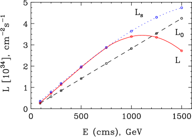
Luminosity as a function of energy (cms) is shown in Fig. 6, where nominal parameters for 250 GeV beams are used for all energy variation. A significant reduction of at high energy is explained by the effects of synchrotron radiation in the FF bends and quadrupoles. As the energy increases, the beam size decreases as which reduces high order geometric aberrations. But energy spread created by synchrotron radiation in bends increases with energy and enhances chromatic aberrations. This results in the luminosity loss if the non-linear correction is not reoptimized. Using the bend scaling method, compensation can be improved and most of the luminosity recovered. For peak luminosity at high energy, the bending angles were scaled down which reduced dispersion and energy spread from synchrotron radiation. The corrector strengths were correspondingly scaled up, but it was acceptable since geometric aberrations were reduced due to the smaller beam size. The full range of the scaling factor was from 2.76 at GeV (cms) to 0.42 at 1.5 TeV. Reoptimization of the final doublet length to minimize synchrotron radiation effects would keep the luminosity increasing at energy higher than 1.5 TeV (cms).
2.3 Comparison with Analytical Calculation
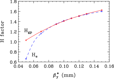
Accuracy of the empirical formula for luminosity enhancement factor [1] was verified by comparison with the GUINEA-PIG simulations. The factor includes the hourglass reduction and pinch enhancement effects. Fig. 7 shows the GUINEA-PIG factor and empirical factor versus corresponding to Fig. 2. It follows from Ref. [1] that was derived for and its accuracy is . Fig. 7 shows an agreement of 1-5% between and for , but significantly underestimates luminosity at lower . We conclude that for practical NLC beam parameters the empirical formula provides reasonable estimate of luminosity.
3 CONCLUSION
Tracking and beam-beam simulations in the NLC collimation and FF sections for 250 GeV beams showed that luminosity is at maximum near mm and can be further increased by reducing . Optimization of the non-linear compensation scheme for maximum luminosity is required when beam parameters change, especially at high beam energy. Accuracy of the empirical formula for luminosity enhancement factor was found to be reasonably good for the NLC parameters close to nominal.
References
-
[1]
P. Chen, K. Yokoya, Phys. Rev., D38, p. 987, 1988;
P. Chen, Proc. IEEE PAC93, p. 617, 1993. -
[2]
NLC version of DIMAD,
http://www-project.slac.stanford.
edu/lc/local/AccelPhysics/Accel_Physics_index.htm. - [3] D. Schulte, DESY-TESLA-97-08, 1997.
- [4] B. Dunham, O. Napoly, DAPNIA-SEA-94-06, 1994.
- [5] P. Raimondi, A. Seryi, Phys. Rev. Let., 86, p. 3779, 2001.
- [6] M.A. Furman, SLAC-ABC-41-REV, 1991.