Photonic Approach to Making a Left-Handed Material
Abstract
A new approach to producing a composite material with negative refraction index is demonstrated. It is shown that a photonic structure consisting of two dielectric materials, with positive and negative dielectric permittivities, can support electromagnetic surface waves which exhibit the unusual electromagnetic property of left-handedness (or negative refraction index). Depending on the dielectric materials, these surface waves localized at the dielectric interfaces can be either surface plasmons, or phonons. The detailed geometry of the structure determines whether this composite left-handed material is isotropic, or anisotropic.
I Introduction
Electromagnetic (EM) properties of materials can be characterized by two macroscopic quantities: dielectric permittivity and magnetic permeability . Propagation properties of EM waves in the material is determined by and which regulate the relationship between the electric field and the magnetic field . Those propagation properties may depend on the frequency of the waves since both and are, in general, frequency-dependent.
For the overwhelming majority of materials both and are positive in the propagation frequency band. Therefore, in most materials, as well as in vacuum, the relationship between , , and propagation wave vector is given by the right hand rule: . The consequence of this is that the group velocity (where is the Poynting flux of the wave and is the wave energy density) of the propagating wave packet points in the same direction as its phase velocity .
It was first pointed out by Veselago [1] that wave propagation is also possible in materials which have simultaneously negative and . Since in such environments the relationship between , , and is given by the left-hand rule, such materials are referred to as the Left-Handed Materials (LHMs). Their electromagnetic properties are significantly different from those of the right-handed materials because the group and phase velocities of electromagnetic waves in LHMs oppose each other: . For example, an electromagnetic wave incident on an interface between the right and left-handed materials stays on the same side of the interface normal [1]. In other words, its refracted angle is negative. This property gives rise to another name for the LHMs: materials with negative index of refraction [2]. Also, the sign of the Doppler effect is reversed in LHMs: an approaching source appears to emit higher frequency waves than the receding one.
LHMs have recently attracted significant attention because of their promise for developing the so called “perfect” lenses [3] and low reflectance surfaces [2]. “Perfect” lens enables focusing electromagnetic waves to a spot size much smaller than the wavelength . Conventional lenses do not permit the image to be significantly sharper than .
Since materials with do not naturally occur, LHM has to be artificially constructed. An LHM in the microwave frequency band was recently constructed [4] as an array consisting of metal rods (which provided [5]) and split-ring resonators (which provided [6]). Photonic structures have also been known to exhibit negative group velocity due to the band folding effect [7]. Below I introduce a new concept of making an LHM by creating a photonic structure consisting of dielectric regions with separated by thin vacuum gaps. Left-handedness of such structures is due to the existence of the surface waves at the vacuum/dielectric interfaces. Depending on the nature of the negative material used, those surface waves could be either surface plasmons, or surface phonons.
Practical implementation of such photonic structures at a micron scale is encouraged by the availability of low-loss dielectrics and semiconductors with negative , including many polar crystals such as SiC, LiTaO3, LiF, and ZnSe. The frequency-dependent dielectric permittivity of these crystals, given by the approximate formula [8] is negative for . Another example of a medium with is the free electron gas with , where is the plasma frequency. Its dielectric permittivity turns negative for .
The major innovation introduced in this paper is the use of the dielectric materials with small (of order ) negative dielectric permittivity in order to construct a left-handed composite material. This is significantly different from earlier work [4] where a periodic arrangement of metallic components was assembled to achieve left-handedness in the microwave frequency range. For microwave, as well as infrared, frequencies the dielectric permittivity of metals is essentially .
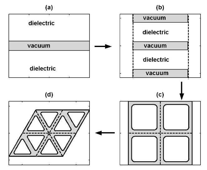
The organization of the remainder of the paper is schematically shown in Fig. 1. In Section II a single dielectric waveguide (SDW) with dielectric cladding (Fig. 1(a)), is shown to exhibit left-handedness due to the existence of the surface waves at the vacuum-cladding interface. The effective and of the waveguide are shown to be negative (see Fig. 2). Two types of surface waves are considered: surface plasmons at the vacuum/plasma interface, and surface phonons at the interface between vacuum and silicon carbide (SiC). Due to its remarkable property of having the dielectric permittivity at the wavelength (m) produced by the conventional CO2 lasers, silicon carbide is also proposed as the solid state medium for making a near-field “perfect” lens: the tool for enhanced near-field imaging in mid-infrared (see Fig. 4).
Of course, surface waves can only propagate along (and not across) the waveguide walls. Section III consider a stack of dielectric waveguides (Fig. 1(b)), which supports waves propagating in all directions. Only the waves propagating in a limited range of directions, however, exhibit the property (where and are the group and phase velocities). Therefore, the waveguide stack (WS) is not a proper LHM, and the two-dimensional photonic waveguides shown in Fig. 1(c,d) are considered in Sections IV,V as the further refinements of the concept. The square lattice photonic waveguide (SLPW) turns out to be a highly anisotropic LHM, with the angle always satisfying but strongly dependent on the propagation direction (see Fig. 6). SLPW is anisotropic even for small wavenumbers. This result is explained using the standard perturbation theory. The triangular lattice photonic waveguide (TLPW) is found to be a perfectly isotropic LHM for small wavenumbers , where is the lattice periodicity. Recently [9], it has been suggested that the group velocity in LHMs is not aligned with the phase velocity, making the perfect lens impossible. It is constructively demonstrated that this is not the case even for an artificially constructed LHM shown in Fig. 1(d). The main results are summarized in Sec. VI.
II Propagation of Surface Plasmons and Phonons in a Single Dielectric Waveguide
To illustrate how a negative can be mimicked using only dielectrics with negative , consider electromagnetic wave propagation in the horizontal () direction in a dielectric waveguide shown in Fig. 1(a), with a piecewise constant dielectric constant: in the vacuum channel (for ) and inside the cladding (for ). Consider a confined transverse magnetic (TM) wave with non-vanishing components (, , ), and assume, by symmetry, that at . Since we are interested in the wave propagation along , introduce integrated over the transverse direction quantities
From Faraday’s and Ampere’s laws, assuming that and integrating by parts, obtain, correspondingly,
| (1) |
where the effective dielectric permittivity and magnetic permeability of a dielectric waveguide are defined as follows:
| (2) |
The definition of the weight-averaged is intuitive, and is defined so as to eliminate the longitudinal component of the electric field which does not contribute to the power flow along the waveguide.
Equations (1) yield , necessitating that and be of the same sign for a propagating wave. Note that is a complicated function of the channel width, frequency, and the dielectric constant of the cladding, and could generally be either positive or negative. Also, the propagating mode is left-handed only if , necessitating that the dielectric constant of the cladding be negative.
Calculating and requires the exact mode structure in the waveguide. The equation for is
| (3) |
and for the SDW case the harmonic dependence is assumed. Introducing , for , the mode structure is given by for and for . It is a surface wave because it is localized near the vacuum-cladding interface. Continuity of requires the continuity of across the vacuum-cladding interface at . The dispersion relation v. s. is found by solving the boundary condition equation simultaneously with the equations for and . Expressions for the effective permittivity and permeability are given by
| (4) | |||
| (5) |
and similar equations are obtained for the sub-luminal mode with .
Two cladding materials are examined below: a plasmonic material, and a polar dielectric silicon carbide (SiC). Plasmonic materials are characterized by the frequency-dependent dielectric permittivity , where is the plasma frequency, and is the damping constant. At optical frequencies most metals can be considered plasmonic materials. Surface plasmons exist at the interface between a plasmonic material and another dielectric (or vacuum) with positive dielectric permittivity. Silicon carbide is a low-loss polar dielectric which exhibits Restsrahlen: it’s dielectric permittivity is negative for frequencies , where cm-1 and cm-1.
A Plasmonic Dielectric Cladding
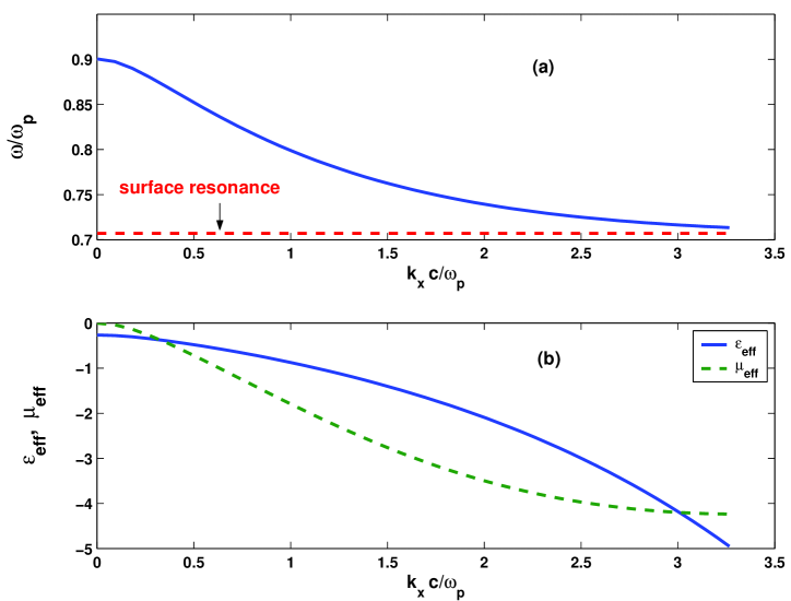
The dispersion relation and the corresponding and are plotted in Fig. 2(a,b) for a SDW with plasma-like cladding () and the gap width . The propagating surface mode in a SDW exists at the vacuum/plasma interface – therefore it is a surface plasmon. This surface plasmon exhibits left-handedness: it’s group velocity is negative, and so are and . The cutoff at is caused by the vanishing of the . This is very different from the cutoff at in a homogeneous plasma-like medium which is caused by the vanishing of . Note that two vacuum/plasma interfaces are required to make a surface plasmon left-handed.
Why is despite ? The total Poynting flux along the dielectric waveguide is the sum of the fluxes inside the cladding and in the vacuum gap. In the gap, and are in phase, so . Inside the cladding reverses its sign across the vacuum/cladding interface because , and the electric displacement vector is continuous. is continuous across the interface, resulting in in the cladding. For a narrow gap, the integrated Poynting flux is negative, and the mode is left-handed.
We emphasize that not any surface wave is left-handed. Achieving left-handedness requires that (a) the frequency of the mode lies within the stop-band of the cladding (so that ), (b) there are two interfaces, and (c) the vacuum gap between the interfaces is small. The gap between the two claddings with need not be vacuum – it can be filled with another dielectric which has a positive dielectric permittivity to enable the existence of the surface waves. The cladding with also needs not be plasma-like. In the next section the silicon carbide cladding is considered.
B Silicon Carbide Dielectric Cladding
Silicon carbide (SiC) is a polar dielectric [10] with very interesting photonic properties because its dielectric permittivity is of order for the wavelengths close to microns. Therefore, a micron-scale waveguide with SiC cladding supporting left-handed surface phonons with the frequency corresponding to the vacuum wavelength of m can be envisioned. The frequency dependent dielectric permittivity of SiC is given by [10]
| (6) |
where , cm-1, cm-1, and cm-1.
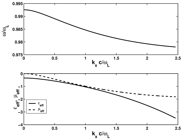
The dispersion relation and the corresponding and are plotted in Fig. 3(a,b) for a SDW with the SiC cladding and the gap width . The small damping constant was neglected. The left-handed surface mode is a surface phonon. Qualitatively, there is a similarity between the electromagnetic properties of a left-handed plasmon (shown in Fig. 2) and those of a left-handed surface phonon (shown in Fig. 3). Both exhibit negative group velocity and negative , .
One essential difference is that the group velocity of the surface phonon is much smaller than that of the surface plasmon. This is related to the large energy density of the polaritons (coupled phonon polarization and photon waves) in SiC. The energy density is proportional to which is proportional to . Both the large value of and the narrow width of the reststrahlen band (between and ) contribute to the small group velocity of the surface phonons.
Note that there exists a frequency for which both and are approximately equal to . A composite material with was shown to be ideal for making a “perfect” lens [3] which is capable of imaging objects much smaller than the wavelength of light.
Another type of a near-field lens which does not require (although still requires ) was also recently suggested [3, 11]. It was concluded that a thin slab of material with can produce images of sub-wavelength objects with the resolution which by far exceeds that of the conventional lenses or even near-field imaging. Unfortunately, finding the appropriate material with is challenging. Gaseous plasma was suggested as a possible candidate for enhanced near-field imaging in the microwave frequency range [11].
Unfortunately, the microwave frequency (or the resolution accomplished with microwaves) may be too low for many applications. Another promising idea of using thin metal layers [3] for enhanced near-field imaging requires extremely thin (less than Angstroms) films and very short wavelengths (m for Ag films). The reason I’ve chosen SiC as the exemplary ingredient for making a left-handed material is that it may be interesting from the technological standpoint: its dielectric permittivity for the frequency corresponding to the vacuum wavelength of m. This wavelength is produced by the widely available CO2 lasers. To illustrate the resolution achievable by the combination of a CO2 laser and a thin film of SiC, consider the image of a narrow (sub-wavelength) slit produced by a film of SiC of the width m.
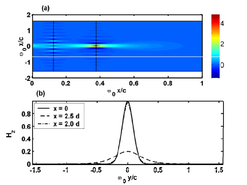
Two-dimensional geometry is assumed, and a thin source at is assumed to be infinitely extended in the direction while having the Gaussian shape in the direction. Transverse magnetic (TM) mode (with field components , , and ) is assumed, and the prescribed magnetic field at the slit with m is assumed. The thin SiC film is located between and .
The two-dimensional distribution of the magnetic field in the rectangular area and is shown in Fig. 4(a). The profiles of in three planes: at (which represents the original shape of the sub-wavelength slit), at (the imaging plane), and (the SiC slab width behind the image plane), are plotted in Fig. 4(b). The enhanced near-field image at is practically indistinguishable from the shape of the slit at , and is of much higher fidelity than the un-enhanced near-field at . Therefore, this numerical example demonstrates the higher fidelity of the enhanced near-field imaging in comparison with the standard one.
To my knowledge, the idea of using a low-loss polar dielectric with the reststrahlen band for enhanced near-field infrared imaging with sub-micron resolution is presented here for the first time. Possible applications include nano-lithography using a CO2 laser and high-resolution biological and chemical sensors.
III Waveguide Stack
The SDW was considered merely to elucidate the emergence of the left-handed surface waves, and to derive the necessary conditions (a-c) for their existence. The objective of this Letter is to construct a photonic structure capable of transmitting infinitely extended (planar) left-handed waves in all directions. SDW is not infinitely extended in direction, and it only enables wave propagation in direction. Thus, the waveguide stack (WS) with periodicity in direction, shown in Fig. 1(b), is considered next. The elementary cell of a WS is assumed to have the piecewise constant dielectric permittivity: for and for . Electromagnetic waves in a WS are characterized by the two numbers: phase shift per unit cell and the wavenumber . Electromagnetic waves in a periodically layered medium have been intensely studied since the 70’s [12], but without the emphasis on surface waves which can exhibit left-handedness.
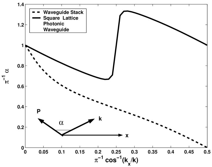
Assuming that , , and , the dispersion relation in the WS was numerically calculated by integrating Eq. (3) between and and requiring that . It is found that , . Therefore, waves propagate as left-handed along the -direction, and as right-handed along the direction. The angle between the phase and group velocities in the WS is plotted as the dashed line in Fig. 6 v. s. the angle between the wavenumber and the axis. For small , (), and the waves are essentially left-handed. However, for large , , and the waves are right-handed. Therefore, the waveguide stack is not an LHM.
IV Electromagnetic Properties of Square Lattice Photonic Waveguide
To ensure that surface waves can propagate in direction, an additional set of vertical channels is introduced, as shown in Fig. 1(c). Rectangular regions of the dielectric are separated from each other by a network of orthogonal vacuum channels which form a square lattice with the period . The channel widths are , and the dielectric boundaries are rounded with the radius . Wave propagation along the resulting square lattice photonic waveguide (SLPW) is characterized by two phase shifts per cell, and . Equation (3) is solved for eigenvalues using a finite elements code FEMLAB [13]. The solution satisfies the following boundary conditions: and [14]. The local and cell-averaged Poynting fluxes are computed for each solution. Since , the angle between and is used to classify waves into left- and right-handed.
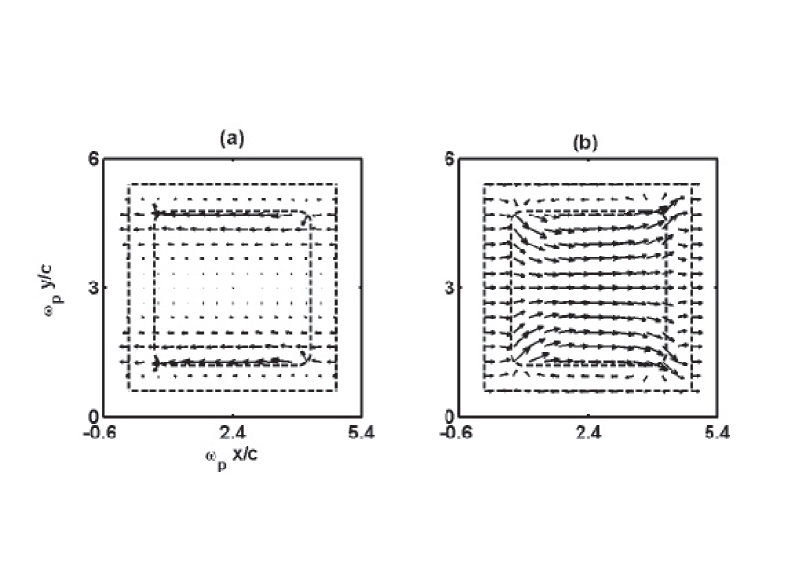
Two classes of electromagnetic modes were found for any given wavenumber . The higher-frequency mode is right-handed, and the lower-frequency mode is left-handed. The physical difference between these modes is illustrated by Fig. 5, where the local Poynting fluxes are shown for , . The Poynting flux of the left-handed mode () shown in Fig. 5(a) is localized near the vacuum/cladding interfaces, and points in the negative direction. The mode clearly propagates as a surface wave. In contrast, the right-handed mode () propagates by tunneling across the dielectric cladding, which is why the Poynting flux is positive and not localized, as shown in Fig. 5(b). The two modes have exactly the same frequency (i. e. are degenerate) for . As will be demonstrated below, the mode degeneracy results in the strong anisotropy of the propagating modes with small (but finite) wavenumbers : the mode frequency not only depends on , but also on its direction .
The angle is plotted in Fig. 6 as the function of the propagation angle for the lower-frequency mode of the SLPW. In an isotropic LHM for any . In general, the medium need not be isotropic, in which case we require that for all propagation directions in order for the medium to be left-handed.
SLPW is an example of such an anisotropic medium: it is strictly left-handed (because for all propagation directions. Group and phase velocities exactly oppose each other for four different propagation directions: . Due to the anisotropy of the SLPW, radiation ”prefers” to propagate along one of the channels. Specifically, for radiation preferentially flows along direction, and vice versa. Symmetry requires that when , so there is a rapid transition near from the preferential flow along for to the preferential flow along for . The rapidity of the transition is determined by the corner curvature of the structure. Note that the anisotropy of the SLPW is not related to the periodicity of the structure. Numerical simulations demonstrate that the SLPW is anisotropic even for small far from the edges of the Brillouin zone.
A Why is SLPW anisotropic for small wavenumbers
The anisotropy of the SLPW for small may be somewhat surprising because it implies that the mode frequency is not an analytic function of . Indeed, if the frequency is a quadratic function of , i. e. (where is the cutoff frequency), then the symmetry of the square lattice requires that , where is the scalar and is the Kronecker delta. This would imply isotropy: from follows that the group velocity is parallel to the phase velocity. However, the frequency is not an analytic function of . This is due to the fact that at the mode is doubly-degenerate (see Fig. 5). Below I illustrate using the perturbation theory that the mode degeneracy implies anisotropy for the SLPW.
The solutions of the Eq. (3) corresponding to the phase shift per unit cell can be expressed as , where is a periodic function. Substituting into Eq. (3) yields
| (7) |
Equation (7) can be recast as an eigenvalue problem , where the distances are measured in units of , is the eigenvalue, is the unperturbed Hamiltonian, is the linear in perturbation, and is the quadratic in perturbation of the Hamiltonian. The total perturbation . The dielectric permittivity the function of . However, for simplicity, I will assume in the following that is frequency independent. For definitiveness, assume that since, for , .
The unperturbed Hamiltonian has a discrete spectrum of eigenfunctions and associated eigenvalues . The lowest eigenvalue is which corresponds to . The next doubly-degenerate eigenvalue is . The corresponding eigenfunctions are odd with respect to inversion: . They can be conveniently chosen such that , , and, correspondingly, , . Note that and are mutually orthogonal. The next closest to eigenvalue is . This a non-degenerate eigenvalue, with the corresponding eigenfunction satisfying the following symmetry properties: , , and .
The -dependent perturbation and removes the degeneracy between and , resulting in the left-handed and right-handed waves shown in Fig. 5 which have different frequencies as indicated earlier. Calculating the mode frequencies in the limit of small can be done in the context of the perturbation theory by solving the secular equation [15]. Defining the overlap integral as
where ’s are the unperturbed solutions, the secular equation takes on the form which is familiar from quantum mechanics: . The summation over the repeated index is assumed, and the sought after n-th perturbed eigenfunction is given by . We are primarily interested in the behavior of the perturbed solutions (lower-frequency left-handed mode) and (upper-frequency right-handed mode) which, in the limit of , become and .
Strictly, all unperturbed eigenfunctions of have to be included in the summation. For simplicity, I only include the two degenerate eigenfunctions , , and the eigenfunctions and which have the closest eigenvalues and . In this truncated model, the degenerate doublet of unperturbed eigenfunctions (,) is “surrounded” by the two singlets and . The four eigenfunctions () are taken to be real and normalized to unity.
Simple symmetry arguments can be used to demonstrate that and , where is a constant. Thus, the perturbation does not mix and , and does not remove the degeneracy of the doublet (,). It is the mixing between the doublet and the two singlets via that lifts the degeneracy, and introduces the anisotropy of the perturbed solutions and . The relevant non-vanishing matrix elements are , , , and . It can be shown that the effect of the non-vanishing matrix elements and (where and are constants) on the doublet is of order . Hence, and are neglected. Also by symmetry, .
The corresponding secular equation for computing the perturbed frequencies of (,) is obtained by solving the following equation [15] for the eigenvalue shift :
| (8) |
where . In the vicinity of , the quatric in Eq. (8) becomes quadratic:
| (9) |
where , , and is the interaction matrix:
| (10) |
Again, symmetry considerations completely determine the functional dependence of the matrix elements on . For example, it can be shown that for the SLPW , , , and . Therefore, the bracketed term in Eq. (8) is the function of only. The vanishing of would then guarantee that is an analytic function of . Not surprisingly, would be an isotropic function of . For the SLPW, however, does not vanish, and
| (11) |
where the () signs correspond to (right-handed) and (left-handed) modes, respectively.
Note from Eq. (11) that is not an analytic function. It is also manifestly anisotropic due to the -dependence of . The two properties (anisotropy and the non-analyticity) go hand in hand: analytic dependence on on implies isotropy in the limit of small . In Section V it is found that a periodic lattice with higher symmetry (Triangular Lattice Photonic Waveguide) is isotropic. This may be explained by the vanishing of due to the higher degree of symmetry of the TLPW.
V Isotropy of Triangular Lattice Photonic Waveguide
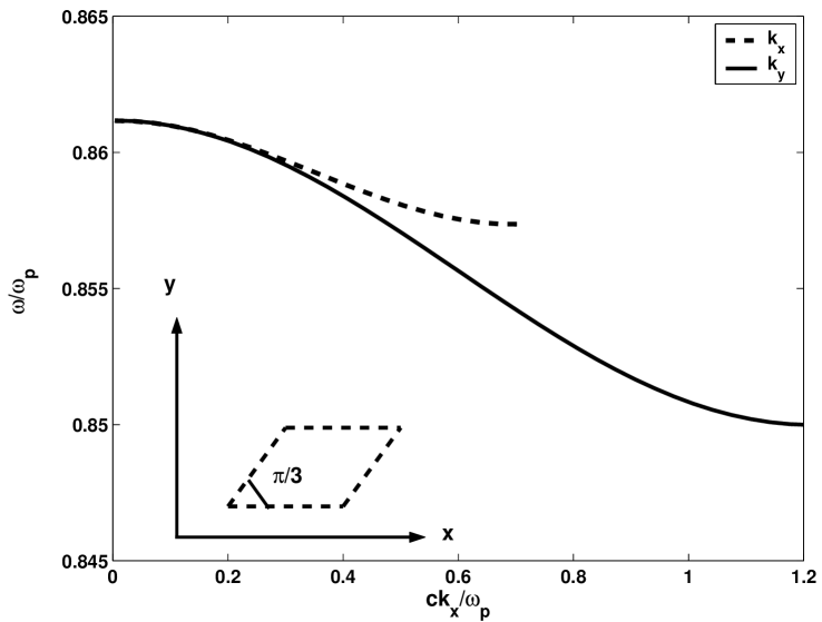
Photonic waveguide can be made much more isotropic if dielectrics are arranged in a triangular lattice, as shown in Fig. 1(d), forming a Triangular Lattice Photonic Waveguide (TLPW). This arrangement has a higher degree of symmetry than SLPW, and results in a composite medium which is perfectly isotropic for small well inside the Brillouin zone. The elementary cell of the TLPW and the dispersion relation v. s. for two orthogonal directions of are shown in Fig. 7. The two dispersion curves, which are identical for (establishing the isotropy), are drawn to the respective edges of the Brillouin zone: and [14].
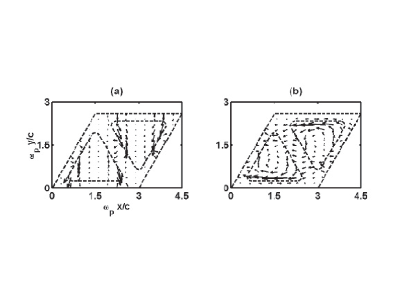
These two directions are chosen because they exhibit the maximum possible anisotropy. Indeed, for there exists a vacuum/cladding interface along which the electromagnetic energy can flow in direction, Fig. 8(b). No such interface exists for , Fig. 8(a). Thus, the local Poynting flux patterns are very different for these two directions, as can be seen by comparing Figs. 8(a,b). For the parameters of Fig. (8), , the index of refraction is . Index of refraction can be readily tuned in both directions by adjusting the parameters of the TLPW: periodicity and channel width .
Despite the differences in the flow patterns, the cell-integrated fluxes are identical for all directions of , and so are the frequencies: . Numerical results unambiguously confirm that, for small , phase and group velocities exactly oppose each other. At least for this particular LHM, the claim of Valanju et. al. [9] that is not confirmed. Anisotropy for large is merely the consequence of the periodicity of the photonic structure.
The angle between the phase and group velocities was calculated as the function of the propagation angle . The propagation wavenumber of magnitude was rotated by varying . The angle for the TLPW was found to vary between . This stands in sharp contrast with the significant deviation of from for the SLPW as shown in Fig. (6). Therefore, it is concluded that, unlike the SLPW, the TLPW is an isotropic (uniaxial) left-handed structure. I speculate that the isotropy is related to the fact that given by Eq. (10) vanishes for TLPW but not for the SLPW.
VI Conclusions
In conclusion, several photonic structures supporting left-handed waves were considered. The structures consist of dielectrics with the dielectric permittivities of the opposing signs, enabling the propagation of the surface waves. Two types of surface waves, plasmons and phonons, were considered. A specific material (SiC) was suggested as the promising candidate for making left-handed photonic structures, as well as for developing a “perfect” lens for enhanced near-field imaging.
The most promising two-dimensional structure with negative index of refraction appears to be the Triangular Lattice Photonic Waveguide because it is isotropic (uniaxial) in the wave propagation plane. The simpler left-handed structure, the Square Lattice Photonic Waveguide, was shown to be anisotropic even for infinitesimally small propagation wavenumbers. This was shown to be the consequence of the non-analytic dependence of the wave frequency on its wavenumber.
I would like to acknowledge the enlightening conversations with Dr. D. J. Bergman and Dr. R. C. McPhedran on the anisotropy of the square lattice photonic waveguide.
REFERENCES
- [1] V. G. Veselago, Sov. Phys. Uspekhi 10, 509 (1968).
- [2] D. R. Smith and N. Kroll, Phys. Rev. Lett. 85, 2933 (2000).
- [3] J. B. Pendry, Phys. Rev. Lett. 85, 3966 (2000).
- [4] D. R. Smith, W. J. Padilla, S. C. Nemat-Nasser, and S. Schultz, Phys. Rev. Lett. 84, 4184 (2000).
- [5] W. Rothman, IRE Transactions on Antennas and Propagation, AP-9, 82 (Jan. 1962).
- [6] J. B. Pendry, A. J. Holden, D. J. Robbins, and W. J. Stewart, J. Phys. Cond. Matter 10, 4785 (1998).
- [7] M. Notomi, Phys. Rev. B 62, 10696 (2000).
- [8] Kittel, Introduction to Solid State Physics, John Wiley Sons, New York (1976).
- [9] P. M. Valanju, R. M. Walser, and A. P. Valanju, Phys. Rev. Lett. 88, 187401 (2002).
- [10] W. G. Spitzer, D. Kleinman, and J. Walsh, Phys. Rev. 113, 127 (1959).
- [11] J. T. Shen and P. M. Platzman, Appl. Phys. lett. 80, 3286 (2002).
- [12] P. Yeh, “Optical Waves in Layered Media”, John Wiley and Sons, 1988.
- [13] FEMLAB Reference Manual, Version 2.2, November 2001, Comsol AB, Sweden.
- [14] E. I. Smirnova et. al., J. Appl. Phys 91, 960 (2002).
- [15] J. J. Sakurai, Modern Quantum Mechanics, Revised Edition, Addison-Wesley, Reading MA, 1994.