Fiber-coupled Antennas for Ultrafast Coherent Terahertz Spectroscopy in Low Temperatures and High Magnetic Fields
Abstract
For the purposes of measuring the high-frequency complex conductivity of correlated-electron materials at low temperatures and high magnetic fields, a method is introduced for performing coherent time-domain terahertz spectroscopy directly in the cryogenic bore of existing dc and pulsed magnets. Miniature fiber-coupled THz emitters and receivers are constructed and are demonstrated to work down to 1.5 Kelvin and up to 17 Tesla, for eventual use in higher-field magnets. Maintaining the sub-micron alignment between fiber and antenna during thermal cycling, obtaining ultrafast ( fs) optical gating pulses at the end of long optical fibers, and designing highly efficient devices that work well with low-power optical gating pulses constitute the major technical challenges of this project. Data on a YBCO superconducting thin film and a high mobility 2D electron gas is shown.
pacs:
PACS numbers:Introduction
Time-domain terahertz spectroscopy is an established technique for the measurement of high-frequency conductivity, typically in the range between 100 GHz and 3000 GHz. Pioneered in the late 1980s[1, 2], “table-top” terahertz spectrometers employing photoconductive antennas gated by ultrafast optical pulses have been used to study a wide range of material systems, including semiconductors and dielectrics[3], normal and high- superconductors[4, 5], liquids[6], flames[7], and gases[8]. This THz frequency range lies between that which is readily accessible by microwave cavity techniques (on the low frequency side), and Fourier-transform infrared spectroscopies (on the high frequency side). These frequencies correspond to energies between 0.4 meV and 12 meV, or alternatively, temperatures between 4K and 140K and magnetic fields between 4 Tesla and 100 Tesla.
This is precisely the energy, temperature, and in particular the magnetic field scale relevant to many novel correlated-electron systems of interest today, including high- superconductors (where the upper critical field corresponds to tens or even hundreds of Tesla[9]), heavy-fermion and Kondo-insulating materials (where, e.g., the Kondo spin/charge gap in Ce3Bi4Pt3 may be closed above 30 T[10]), colossal magnetoresistive manganites (melting of charge/orbital order at high fields[11]), 2D electron gases (composite fermion dynamics in the high-field fractional quantum Hall regime), and organic metals (novel field-induced superconductivity above 17 T[12]). Thus it is of keen interest to perform measurements of the complex THz conductivity not only in the regime of low temperatures, but also at high magnetic fields. However, the conventional “table-top” transmission terahertz spectrometer is a rather involved and physically large setup, typically utilizing several micropositioning stages to align the THz antennas with respect to the free-space laser beams, and off-axis parabolic optics to collimate and focus the terahertz pulses over short distances. These traditional methods work extremely well, but are not compatible with high-field magnets (10-60 T), which are generally solenoids with narrow, cryogenic bores accessible primarily via meters-long experimental probes.
To this end we have developed extremely sensitive, miniaturized, optical fiber-coupled THz emitters and receivers for remote use directly in the low-temperature bore of a high-field (dc or pulsed) magnet. These devices permit ultrafast, coherent, time-domain THz transmission spectroscopy of samples in the frequency range between 100 GHz and 2000 GHz. Due to the coherent nature of the detection (both amplitude and phase of the THz electric field are measured), the complex conductivity may be directly evaluated without the need for Kramers-Kronig analyses, in contrast with phase-incoherent schemes based on thermal cyclotron emission[13]. The gated nature of the detection permits high signal-to-noise data with minimal (2 mW) optical power input and, where necessary, the ability to acquire complete spectra in tens of milliseconds. The primary challenges of this project include maintaining sub-micron alignment between fiber and antenna upon repeated thermal cycling, achieving ultrafast ( fs) optical pulses at the end of tens of meters of singlemode optical fiber, and obtaining complete time-domain scans with high signal-to-noise ratio using only milliwatts of optical power, no lock-in detection, and (for pulsed magnets) only 100 ms of integration time.
Experimental setup
Using photoconductive antennas, wide-bandwidth THz pulses may only be generated (and detected) by gating the antennas with ultrafast optical pulses, and for this reason it is necessary to compensate for the positive group-velocity dispersion (GVD) of optical fibers so that fast optical pulses may be obtained at the ends of long fibers. Normal silica optical fiber exhibits a GVD of roughly 120 fs/m-nm at 800 nm, so that without compensation, a 100 fs input optical pulse with a bandwidth of 10 nm broadens, in the best case, to picoseconds after a typical 20 meter length of fiber. Such a lengthy optical pulse is useless for generating or detecting THz radiation. Thus it is necessary to precompensate and impose a negative chirp on the optical pulses before launching into the optical fibers, so that the optical pulses shorten in time as they travel through the fiber and achieve a minimum value right at the THz devices.
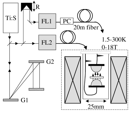
The experimental schematic for THz transmission spectroscopy in high-field magnets is illustrated in Fig. 1. Ultrafast optical pulses (100 fs, centered at 800 nm) from a commercial Ti:sapphire laser are directed to a two-grating pulse stretcher, which imparts a negative chirp (blue wavelengths leading red wavelengths) onto the pulses. The magnitude of the negative chirp, tuned via the separation between the two gratings G1 and G2 (1200 grooves/mm), is chosen to optimally compensate for the intrinsic positive GVD of optical fiber, and thus depends on the laser wavelength and the length of fiber used. For typical fiber lengths of 20 meters, the 100 fs, transform-limited pulses are stretched to approximately 24 picoseconds. After leaving the pulse stretcher, the negatively-chirped pulse train is equally split into an “emitter” and a “receiver” beam. The former is launched directly into a singlemode optical fiber, while the latter is delayed by a scanning retroreflector before being launched into another singlemode fiber of equal length. As the optical pulses travel from the laboratory to the low-temperature probe housing the THz antennas, their temporal width decreases due to the positive GVD of the fiber, achieving a minimum pulsewidth directly at the lithographically-defined photoconductive antennas. The minimum pulsewidth depends critically on pulse energy, fiber length, and stretcher position as discussed in detail below. The receiver’s fiber passes through a polarization controller (PC), as it was found that the signal amplitude depends slightly () on the polarization of the optical pulses incident on the THz receiver.
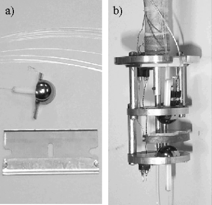
In an experiment, the sample of interest is positioned between the THz emitter and receiver in the cryogenic bore of the magnet. Following the usual prescription, an ultrafast optical pulse promotes mobile carriers in the biased stripline emitter, and the subsequent current surge generates a burst of broadband THz radiation which is coupled into free space through a silicon hyperhemispherical substrate lens of radius 2-5 mm. The height of the substrate lens is chosen to collimate the THz radiation. After passing through the sample, the THz pulse is focussed onto the stripline receiver by another substrate lens, where the “instantaneous” THz electric field is gated by a second ultrafast optical pulse, generating a measurable current. The complete time-dependent THz electric field is mapped by rapidly scanning the time delay between the excitation and gating optical pulses, and the amplified current signal is sent directly to a digitizing oscilloscope. Photographs of a fiber-coupled antenna and of the actual apparatus are shown in Figure 2. The THz emitter and receiver are mounted facing one another with a gap of roughly 1 cm. The emitter bias is provided by twisted-pair leads and external batteries (10-20 V, typically). The detected photocurrent is coupled from the receiver to an external current amplifier (DL Instruments model 1212) via a micro-coaxial cable selected for its low loss and insensitivity to microphonic noise. A rotating copper sample stage enables the sample to be moved out of the THz beam path, so that a reference scan (crucial for quantitative interpretation of data) may be taken at each new temperature or field. Temperature control is provided by a Cernox thermometer in the sample stage and a wire heater on the body of the probe. The entire probe is 25 mm in diameter, and may be used in vacuum, vapor, or liquid helium environments .
Pulse dispersion management in long fibers
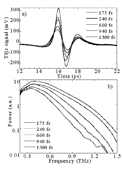
The power and bandwidth of the generated THz radiation is strongly influenced by the temporal width of the ultrafast optical pulses that are used to gate the antennas. Fig. 3 shows the signal ( THz electric field) for a fiber-coupled emitter/receiver pair that are driven by 800 nm optical pulses of constant energy (26 pJ/pulse), but varying pulsewidth. Here, the optical pulsewidth at the antennas is varied between 175 fs and 1300 fs by changing the spacing between the gratings in the pulse stretcher. The effects are immediately clear: Both the amplitude and bandwidth of the measured THz radiation decrease as the temporal width of the optical gating pulses is increased from the minimum value of 175 fs. The drop in power is particularly marked at higher frequencies; e.g., above 800 GHz the power spectrum of the THz pulses (Fig. 3b) decreases over an order of magnitude.
After propagating through a typical length of 10-20 m of optical fiber, the minimum temporal width of an optical pulse is always somewhat larger than the original 100 fs, even when the positive GVD of the optical fiber is optimally balanced by the pulse stretcher. The main reasons for this are uncompensated cubic phase dispersion in the stretcher/fiber system, and self-phase modulation (SPM) in the optical fiber. Quadratic, cubic, and higher-order phase dispersion of an optical pulse in fiber arises simply because the index of refraction of silica (or any material) is not constant with wavelength, and thus different wavelengths within a broadband ultrafast optical pulse travel with different group velocities. Whereas the negative quadratic phase dispersion (GVD) imparted by the pulse stretcher may be tuned to exactly cancel the positive quadratic phase dispersion of the fiber, both the stretcher and the fiber impart a small cubic phase dispersion onto the optical pulse, and these contributions do not cancel. Indeed, it is only by rather involved design, or via the inclusion of phase-shifting optics, that cubic phase dispersion may be compensated[14]. For the purposes of generating and detecting THz radiation, the pulse broadening due to cubic phase dispersion does not degrade the signal significantly to warrant correction, although for longer lengths of fiber ( m) correction may be necessary.
Self-phase modulation, on the other hand, is an inherently nonlinear optical phenomenon arising from an intensity-dependent phase shift, whose effect is to redistribute energy within an optical pulse to different spectral components. Thus, unlike the linear effects of GVD (quadratic) or cubic phase dispersion, SPM acts to create or remove additional wavelengths within the optical pulse. Because SPM in fibers arises from the high instantaneous power in ultrafast optical pulses, it may be minimized by using very low-power pulses, typically of order 30 pJ or less for 100 fs pulses.
The combined effects of SPM, cubic phase dispersion, pulse power, and stretcher position on the optical pulsewidth are shown in Figure 4. Here, prechirped 100 fs low-power (closed circles) and high-power (open circles) optical pulses centered at 800 nm are launched into 20 meters of optical fiber, and the temporal width of the pulses at the end of the fiber is measured as a function of stretcher position. The pulsewidth is measured via autocorrelation and a pulse shape is assumed. At one extreme, when the distance between the two stretcher gratings is 15 mm longer than the optimum separation of 160 mm, the pulses are “overstretched”, and therefore never achieve their minimum value in the optical fiber (i.e., the pulses are still somewhat negatively chirped at the fiber exit). As the distance between the gratings is decreased, the pulses exit the fiber with shorter and shorter pulsewidth until an optimum position is reached and the GVD of the fiber is exactly compensated. Further decreasing the distance between the gratings results in “understretched” pulses, where the minimum pulsewidth is achieved somewhere within the optical fiber (rather than at the end). Note that the minimum pulsewidth for the low-power pulses (250 fs) is larger than the 100 fs input pulsewidth. Since further reduction of the pulse energy has very little effect on the shape of this curve (not shown), the 250 fs pulsewidth is due to the uncompensated cubic phase dispersion of the stretcher-fiber combination (also, similar experiments in 10, 5, and 1 meter fibers show that the minimum pulsewidth approaches 100 fs).
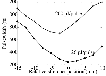
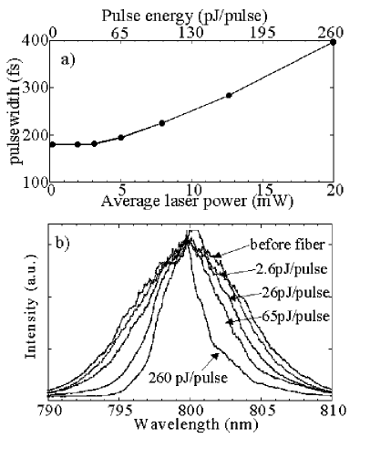
More interesting are the data from the high-power pulses, which exhibit a much larger minimum pulsewidth of 700 fs (and, this minimum value occurs at a slightly different position of the stretcher). In this case, the effects of nonlinear SPM, arising from the large instantaneous intensity of the high-power pulse, actually narrows the spectral bandwidth of the optical pulse, thereby preventing the optical pulse from attaining a small temporal width, even if the pulse were transform-limited. SPM-induced spectral narrowing in a 10 meter optical fiber is explicitly shown in Fig. 5. As a function of pulse energy, the minimum attainable pulsewidth at the fiber exit is shown in Fig. 5a. Figure 5b shows the associated spectral content of these pulses, normalized for comparison. For pulse energies below 26 pJ/pulse, the minimum obtainable pulsewidth remains unchanged at 175 fs, and the spectral content of these pulses is relatively constant and equal to the spectrum of the pulses before entering the optical fiber, indicating that nonlinear (SPM) effects in the fiber are not significant. For pulse energies above 26 pJ, SPM causes the minimum pulsewidth to grow dramatically from 175 fs, reaching a value of 400 fs at 260 pJ/pulse, or 20 mW of average laser power. The spectral bandwidth of the pulses shrinks correspondingly, from a value of 10 nm for low-power pulses, to just under 3.5 nm for the 260 pJ pulses. Although it stands in contrast to the much more well-known and widely exploited spectral broadening which occurs for positively-chirped or transform-limited optical pulses, SPM-induced spectral narrowing of negatively-chirped optical pulses has been previously studied[15], and further, might even be exploited as part of a system for fiber delivery of ultrafast nanojoule optical pulses[16]. Regardless, it is clear that the deleterious effects of SPM on the temporal width of the optical pulses (and subsequently on the THz bandwidth and power) requires that the optical pulse energies be kept very low – less than 30 pJ/pulse, or 2.3 mW average power from the 76 MHz repetition rate Ti:S laser.
Antenna design and construction
The stringent upper limit on the energy of the optical gating pulses mandate the use of specially-designed THz emitter and receiver antennas for maximum emission efficiency and detection sensitivity when coupled to single-mode optical fibers. Additionally, to minimize the thermal load at liquid helium temperatures ( K), it is desirable to design THz antennas which operate efficiently using as little laser power as possible (in practice, 1-2 mW). For the most part, the THz devices are “standard” photoconductive striplines[2] deposited via photolithography onto semiconductor substrates, with 10-20 micron wide, 1 cm long, titanium-gold lines separated by 50-100 microns. Following the work of Brener et al.[17], the THz emitter also incorporates opposing triangular features at the midpoint of the stripline to concentrate the electric field in a localized region so as to enhance the THz output. The gap between the tips of the triangular features is 5 microns, chosen to match the mode-field diameter of the single-mode fiber. Similarly, the THz stripline receiver incorporates a standard dipole, again with a 5 micron gap. The semiconductor substrates are ErAs/GaAs superlattices grown by molecular-beam epitaxy on GaAs wafers[18]. Here, the ErAs material traps carriers efficiently, resulting in the desired subpicosecond carrier lifetimes necessary for THz photomixing applications. Functionally, this material system is related to low-temperature-grown GaAs (LT-GaAs), but with the added advantages of greater flexibility and control over sample parameters. THz receivers made on ErAs/GaAs superlattices were found to exhibit excellent sensitivity to THz electric fields, on par with that of LT-GaAs and over an order of magnitude more sensitive (per unit power of the optical gating pulse) than implanted silicon-on-sapphire substrates.
Good alignment and bonding of the single-mode optical fiber to the small “sweet spot” of the THz antenna is critical to the construction of a usable THz device, as well over half of the THz signal may be lost if the fiber and antenna become misaligned by as little as 1 micron. Because the devices are used in cryogenic environments and must undergo repeated thermal cycling, proper selection of materials and careful construction are necessary to minimize differential thermal contraction which leads to misalignment (or destruction) of the device. Fiber-coupled THz devices are constructed in the following way: Using an infrared microscope, high-resistivity silicon hyperhemispheres are centered exactly over the antenna dipole on the back side of the wafer, and bonded with a dilute mixture of rubber cement in toluene. Single-mode optical fibers are then epoxied into ceramic ferrules, and polished flush with the face of the ferrule. The ceramic ferrule is then positioned over the THz antenna using an XYZ translation stage with sub-micron actuators (Thorlabs MDT611). The THz emitter is biased (10-20 V), the THz receiver is connected to a fast current amplifier, and optical pulses are coupled into the fibers so that the THz signal may be monitored in real time and used to determine the optimum position of the fiber/ferrule with respect to the antenna. Maximum signal is achieved when the ferrule is nearly in contact with and is positioned exactly over the antenna dipole. Bonding of the ferrule to the antenna is achieved by backing the ferrule away from the antenna and applying an extremely thin layer of clear, degassed Stycast 1266 epoxy to the end of the ferrule, after which the ferrule may again be brought into contact with the antenna and the signal maximized. Once optimized, the epoxy may be left to cure. During alignment, using extremely low-power optical pulses and using viscous (slightly cured) epoxy avoids the formation of bubbles due to local heating from the optical pulses. The resulting bond formed between the ferrule and the antenna is quite robust and rigid, and most importantly, does not suffer any misalignment upon repeated thermal cycling from room temperature to cryogenic temperatures. Use of the ceramic ferrule is important to provide mechanical support for the optical fiber, to match the thermal contraction of the GaAs substrate, and to facilitate the use of as little epoxy as possible. Most epoxies, being polymer-based, exhibit thermal contraction that is much larger than the contraction of the GaAs substrate upon which the THz antenna resides (1.1% total contraction from 300K to 4K for Stycast 1266, as compared to 0.1% net contraction for GaAs), so that thick layers of epoxy invariably shatter the substrate upon cooldown. Devices made with stainless steel ferrules occasionally fail upon cooldown, presumably due to the increased mismatch of thermal contraction between stainless steel (0.3% net contraction) and GaAs. Standard UV-curing optical cements performed poorly under cryogenic conditions, and sub-micron alignment was difficult to maintain during the curing process. To make fiber-coupled THz devices for room-temperature use only, any combination of ferrule and epoxy works well – even gluing a bare cleaved fiber directly to the antenna with a drop of Stycast 1266 is quite reliable, if somewhat flimsy. Alternatively, for room-temperature antennas coupled by short lengths of fiber, at least one very nice complete commercial system exists for THz spectroscopy and imaging applications[19].
Antenna performance
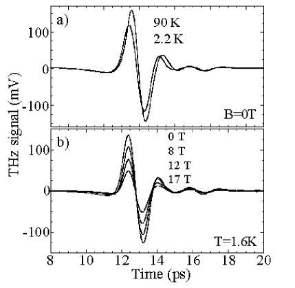
That the fiber-coupled THz antennas perform well at low temperatures and at high magnetic fields is shown in Fig. 6. Here, an emitter and receiver, each coupled by 20 meters of optical fiber, are mounted on the cryogenic probe and loaded in the variable-temperature insert of an 18 T superconducting magnet. The emitter and receiver are driven by 1.5 mW and 2.4 mW of average laser power, respectively. The receiver current is amplified (107 V/A) and sent directly to a digitizing oscilloscope. The amplitude of the measured THz signal varies only slightly upon cooldown from 300K to 1.6K, exhibiting a weak maximum near 100K.
The bandwidth of the THz radiation is unchanged by temperature. THz emitters fabricated on standard semi-insulating GaAs substrates are found to exhibit a much more pronounced temperature dependence, in accord with recent studies by Markelz[20], where the changes are ascribed to the strongly temperature-dependent mobility of electrons in GaAs. The arrival times of the emitter and receiver optical pulses do vary slightly with temperature, presumably due to unequal lengths of thermally-contracted optical fiber in the cryogenic environment, and this causes a small temporal (phase) shift in the measured THz electric field, as can be seen in Fig. 6a at 90K and 2.2K. Because the THz amplitude and phase do vary slightly with temperature, the use of back-to-back sample and reference scans at each new temperature (and magnetic field) is necessary to extract quantitative conductivity data. Fig. 6b shows the performance of the emitter/receiver pair (now immersed in 1.6K superfluid helium) as a function of magnetic field up to 17 T. The amplitude of the THz electric field is attenuated with field, although with no change in bandwidth. Most likely, the applied field acts to bend the trajectories of the photoexcited electrons away from the axis of the antenna dipoles, causing a reduction in signal. It is not knows whether the field predominantly affects the efficiency of the emitter, or the sensitivity of the receiver.

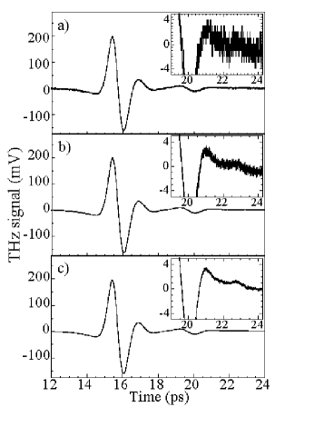
In the data of Fig. 6, 128 sweeps of the 20 Hz scanning retro-reflector are digitally averaged by the oscilloscope, so as to increase the signal-to-noise ratio. Since a long-term goal of this project is to perform ultrafast coherent THz spectroscopy in very high pulsed magnetic fields (and in particular during the 100 ms flat-top of the 60 Tesla Long-Pulse magnet at the Los Alamos magnet lab[10, 21]), it is necessary that these fiber-coupled devices exhibit sufficient signal-to-noise to facilitate THz spectroscopy on short time scales. Figure 7 shows complete THz traces representing 25 ms (one half-cycle of the retroreflector), 100 ms, and 1600 ms of acquired data. The measured root-mean-square noise on each scan (see insets) is 1.06 mV, 0.41 mV, and 0.12 mV, respectively, for signal-to-noise ratios of approximately 190, 490, and 1700. Thus rather precise spectroscopic THz measurements may be performed in high-field pulsed magnets. Of course, in dc magnets (superconducting to 20 T, or resistive to 45 T), no limitations on the amount of averaging time are imposed, and the accuracy of the measurements may be correspondingly increased.
Data
To demonstrate the utility of the fiber-coupled THz antennas, preliminary results on two material systems are shown in Fig. 8 and 9. Here, the experimental probe is loaded into a cryogenic vacuum can in the bore of a 7 T superconducting solenoid. Figure 8 shows the imaginary part of the measured THz conductivity of a high-temperature superconducting YBCO film (50 nm thick, 85K). At low temperatures (Fig. 8a), the conductivity from the Drude-like response of superconducting particles with infinite scattering time is clearly observed. With increasing temperature above this conductivity falls rapidly, indicating the disappearance of phase coherent superconductivity, in agreement with previous works[5, 22]. Fig. 8b shows that similar behavior is observed as a function of magnetic field for temperatures below , indicating again that superconductivity is being suppressed, but this time by the application of magnetic field rather than temperature. By using applied magnetic fields to suppress the superconducting state, these studies will permit investigation of the terahertz complex conductivity of the interesting normal state of high- superconductors at low temperatures below the zero-field , where transport (zero frequency) measurements in pulsed fields have yielded a rich behavior[9].
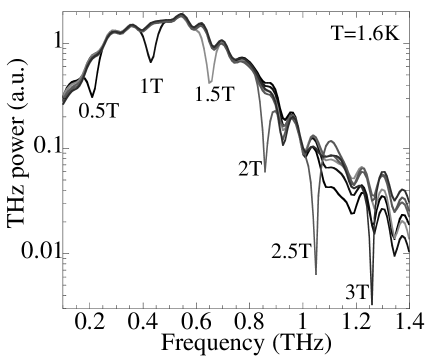
Lastly, Fig. 9 shows data on a very different system; namely, a very high mobility 2-dimensional electron gas ( cm2/V-s) formed at a GaAs/AlGaAs heterojunction. Here, the raw power spectrum of the transmitted THz pulse is shown in the low-field regime where the electron cyclotron energy falls within the THz detection bandwidth. Clear oscillations in the time-domain data (not shown) correspond to the observed cyclotron absorption resonance, which evolves with the expected behavior ( = 1.73 meV/T = 420 GHz/Tesla). The additional oscillations in the power spectrum are an artifact arising from a multiple reflection of the THz pulse which appears 12 ps later in the time domain, and which may be avoided by stacking additional “dummy” wafers of GaAs onto the back of the 2DEG sample. Combined with a carrier density modulation scheme[23] that is synchronized with the scanning retroreflector and digitizer, very sensitive density- and field-dependent studies of the THz conductivity of ultraclean 2D electron systems in the fractional quantum Hall regime may be performed, providing deeper insight into the dynamics and interactions of composite fermions (although generally such studies require millikelvin temperatures and the present apparatus would require adaptation to a dilution refrigerator.)
S.A.C. gratefully acknowledges A. J. Taylor for involvement in this project, and M. Hanson and A. C. Gossard (UCSB) for the ErAs/GaAs material. This work was supported by the NHMFL In-House Research Program.
REFERENCES
- [1] P. R. Smith, D. H. Auston, and M. C. Nuss, IEEE J. Quant. Elect. QE-24, 255 (1988).
- [2] C. Fattinger and D. Grischkowsky, Appl. Phys. Lett. 54, 490 (1989); M. van Exeter, C. Fattinger, and D. Grischkowsky, Appl. Phys. Lett. 55, 337 (1989); N. Katzenellenbogen and D. Grischkowsky, Appl. Phys. Lett. 58, 222 (1991).
- [3] D. Grischkowsky, S. Keiding, M. van Exeter, and C. Fattinger, J. Opt. Soc. Am. B 7, 2006 (1990).
- [4] M. C. Nuss et al., J. Appl. Phys. 70, 2238 (1991);
- [5] See, e.g., M. C. Nuss et al., Appl. Phys. Lett. 58, 2561 (1991); A. Frenkel et al., Phys. Rev. B 54, 1355 (1996); J. Corson et al., Nature 398, 221 (1999).
- [6] J. E. Pedersen and S. R. Keiding, IEEE J. Quant. Elect. 28, 2518 (1992); D. M. Mittleman et al., Chem. Phys. Lett. 275, 332 (1997).
- [7] R. A. Cheville and D. Grischkowsky, Optics Lett. 20, 1646 (1995).
- [8] H. Harde, N. Katzenellenbogen, and D. Grischkowsky, J. Opt. Soc. Am. B, 11, 1018 (1994). D. M. Mittleman et al., Appl. Phys. B, B67, 379 (1998).
- [9] G. S. Boebinger et al., Phys. Rev. Lett. 77, 5417 (1996); S. Ono et al., Phys. Rev. Lett. 85, 638 (2000).
- [10] M. Jaime et al., Nature 405, 160 (2000); G. S. Boebinger, A. Passner, P.C. Canfield, Z. Fisk, Physica B 21, 227 (1995).
- [11] Y. Tokura and N. Nagaosa, Science 288, 462 (2000).
- [12] S. Uji et al., Nature 410, 908 (2001); L. Balicas et al., Phys. Rev. Lett. 87, 067002 (2001).
- [13] P. J. Burke, J. P. Eisenstein, L. N. Pfeiffer, K. W. West, Rev. Sci. Inst. 73, 130 (2002).
- [14] S. Shen and A. M. Weiner, IEEE Photon. Tech. Lett. 11, 827 (1999); C. C. Chang, H. P. Sardesai and A. Weiner, Optics Lett. 23, 283 (1998).
- [15] B. R. Washburn, J. A. Buck, and S. E. Ralph, Optics Lett., 25, 445 (2000).
- [16] S. W. Clark, F. Ilday, and F. W. Wise, Optics Lett. 26, 1320 (2001).
- [17] I. Brener et al., Optics Lett. 21, 1924 (1996); Y. Cai et al., Appl. Phys. Lett. 71, 2076 (1997).
- [18] C. Kadow et al., Appl. Phys. Lett. 75, 3548 (1999); C. Kadow et al., Physica E 7, 97 (2000); C. Kadow et al., Appl. Phys. Lett. 76, 3510 (2000).
- [19] www.picometrix.com; see also J. V. Rudd, D. Zimdars, M. Warmuth, Proc. of the SPIE 3934, 27 (2000).
- [20] A. Markelz and E. J. Heilweil, Appl. Phys. Lett. 72, 2229 (1998).
- [21] S. A. Crooker et al., Phys. Rev. B 60, R2173 (1999).
- [22] R. D. Averitt et al., Phys. Rev. B 63, 140502 (2001).
- [23] D. Some and A. Nurmikko, Appl. Phys. Lett. 65, 3377 (1994).