TUAP066 IMPLEMENTATION OF THE EPICS DEVICE SUPPORT FOR NETWORK-BASED CONTROLLERS
Abstract
Network-based controllers such as PLC’s and measurement stations will be used in the control system of the JAERI-KEK joint project (High Intensity Proton Accelerator Facility). The ability for the network hardware and software to be standardized has led to this decision.
EPICS software support for those controllers has been designed with special attention paid to robustness. This software has been implemented and applied for the accelerator test stand, where the basic functionalities have been confirmed. Miscellaneous functions, such as software diagnostics, will be added at a later date. To enable more manageable controllers, network-based equipment such as oscilloscopes are also being considered.
1 INTRODUCTION
Phase I of the JAERI-KEK joint project for high-intensity proton accelerators was recently approved for construction. The detailed design of the control system is given elsewhere [1]. Because of the recent success of EPICS in the KEKB ring controls[3] and the feasibility to share software resources of accelerator controls with other facilities, the EPICS control software environment[2] has been selected for use in the system.
Internet Protocol (IP) network controllers have been chosen for the controls of the linac portion of the project. The ability to use standard IP network software and infrastructure for both controls and its management[6] influenced our decision. If these controllers meet the performance requirements, as expected, their use may be extended to the entire project.
This article describes the usage plan and the software implementation of such network-based controllers under EPICS.
2 CONTROLLER USAGE UNDER EPICS
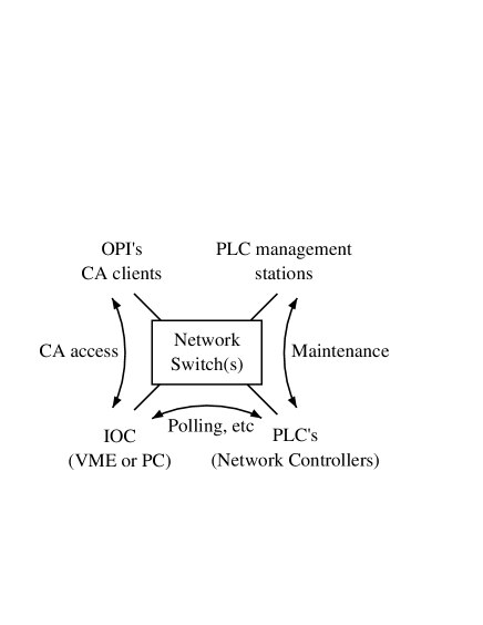
A network-based controller and an EPICS IOC111IOC: input output controller. may be connected with an IP network, as shown in Fig. 1. In this example, a PLC222PLC: programmable logic controller. is used, but other network-based controllers act the same way. Five components in this scheme and their tasks are listed below:
The PLC controls local equipment and carries local processing. An equipment expert usually designs the PLC logic, and it may include a simple local-operation panel. It can be tested by a management station without an EPICS environment. This type of autonomous controllers is useful when a robust control is required.
The IOC processes logic between several PLCs, and keeps their current status in memory. IOCs can be designed by an equipment expert or an operator.
The OPI333OPI: operator interface. has no knowledge of network-based controllers, and therefore interacts with the IOC as usual.
The management station is utilized to develop ladder software which may be downloaded to a PLC, and to diagnose it. The ability to test from outside of the EPICS environment is useful in order to test for errors in the EPICS database or applications themselves.
Network hubs between them should be based on switch technology which does not suffer from message collisions. The design of the network topology is relatively flexible compared with other field networks because of the IP network. A connection to OPIs may be isolated by a network router to limit the communication to PLCs locally.
Figure 1 is symmetric between them, since it shows a physical view. Logically, PLCs are located on a local network while the OPIs are on a global network. They communicate in three ways:
Because a PLC cannot use the EPICS channel access (CA) protocol, a PLC communicates with an IOC with its own protocol. While this protocol is based on polling, an important PLC can send urgent information to an IOC without being requested.
The IOC communicates with OPIs through the normal CA protocol.
The management station maintains PLCs during maintenance periods. Due to the potential number of PLCs that will be in use, it is important to manage them over the IP network.
3 NETWORK-BASED CONTROLLERS
There are three types of network-based controllers being considered for the project:
Programmable logic controllers (PLC) for simple and medium-speed controls.
Measurement stations (Yokogawa’s WE7000) for medium-speed waveform acquisition.
Plug-in network controller boards for magnets with relatively large power supplies.
VME modules installed in EPICS IOCs are used for other purposes, but new network equipment may be added. Measurement equipment, such as network-based oscilloscopes, may be especially useful.
3.1 PLCs
At the electron linac in KEK, central control computers manage approximately 150 PLCs for rf, magnet, and vacuum controls. The PLC, FA-M3 (Factory ACE) from Yokogawa Co., was selected there because of the network software reliability, and the ability to manage the PLCs over an IP network[4, 5]. Even the ladder software is able to be downloaded into a PLC over the network. We have decided to use the same type of PLCs at the joint project as well.
The communication and control routines for PLCs were originally developed for use in a Unix environment. While they were designed to access the shared-memory registers on the PLCs, they can also directly access I/O modules over the network.
Since the routines were written with a generalized IP communication package[7], they were easily ported onto the VxWorks and Windows operating systems. The routines on Windows machines are often useful for developers of ladder software of PLCs even without the EPICS environment.
EPICS device support software has been written utilizing those routines on VxWorks. It provides standard EPICS access methods which can be called from any channel access (CA) clients. Registers are read by and written to the PLCs. Each of registers is specified by an INP/OUT EPICS record field, which uses an IP address, or a host name, and a register address.
The MEDM panel shown in Fig. 2 provides an example of a channel access client. The panel displays current high voltage values and their strip charts for the ion source being conditioned in the linac.

This type of application can be handled by the current software version without problems, but the current implementation of the device support software is not yet optimal. A plan to upgrade the software with a conditional write function, which is described later, may be necessary.
3.2 Measurement Stations
A waveform acquisition is essential to beam instrumentation and microwave measurements. The measurement station, WE7000 from Yokogawa Co. has been well adopted to beam instrumentation at KEK[8]. In addition, their cost performance and electro-magnetic noise elimination are promising.
Three types of waveform digitizers (100ks/s, 100Ms/s and 1Gs/s) are currently considered. We decided to out-source the EPICS device support software, because we thought that it would be a good example of out-sourcing. Although it took some time for the company to understand the EPICS software environment, waveform records have successfully built using disclosed information from Yokogawa. At this time , we are evaluating the performance of the software.
3.3 Plug-in Network Controller
While designing the magnet power supplies for the drift-tube linac (DTL) and the separated-DTL, it was realized that a special type of controller was needed, since power supplies were intelligent and had many functions.
we thus designed a plug-in-type network controller board, which transfers information and commands over the IP network and a local processor located inside a power supply. There are approximately 50 registers, half of which are utilized for network communication and for diagnostic purposes, such as the last IP address accessed.
The controller boards are being built with the power supplies and will be evaluated soon. The software will be very similar and compatible with the PLCs’.
4 CONSIDERATION
Since network-based controllers may reside on a global network, we should be very careful about programming and configuring them. Although the number of persons who access such controllers were limited in the previous project, this may not be the case in the present new project. Therefore, we decided to make several rules for use of the controllers:
We will put an unique identification number (ID) to each PLC and plug-in network controller. Since it will be written in hardware or ladder software, a mistake in the configuration of the IP-address may be found from a management station.
A clock counter of the controller should be consulted routinely from a management station to ensure that it works properly.
While read functions are not restricted, write functions should be limited to some range of register addresses. For important controllers, a value should be always written indirectly with a value and an address.
5 CONCLUSION
The combination of the network-based controllers with the EPICS toolkits will enhance the manageability of the control system. The software for EPICS toolkits has been developed and is currently being tested. They will soon be used in commissioning the first part of the linac.
6 ACKNOWLEDGMENTS
The authors would like to thank the KEKB ring control group people and the joint project staff for valuable discussions.
References
- [1] J. Chiba et al., “A Control System of the Joint-Project Accelerator Complex”, in these proceedings.
- [2] L.R. Dalesio et al., “The Experimental Physics and Industrial Control System Architecture”, Proc. of ICALEPCS93, Berlin, Nucl. Instr. and Meth. A352 (1994) 179.
- [3] N. Yamamoto et al., “KEKB Control System: The Present and the Future”, Proc. of PAC99, New York, USA., 1999, p.343.
- [4] K. Furukawa et al., “Microwave Control and Measurement System at the KEKB Linac”, Proc. of ICALEPCS97, Beijing, China, 1997, p.146.
- [5] N. Kamikubota et al., “Introduction of Modern Subsystems at the KEK Injector- Linac”, in these proceedings.
- [6] K. Furukawa et al., “Network Based EPICS Drivers for PLC’S and Measurement Stations”, Proc. of ICALEPCS99, Trieste, Italy, 1999, p.409.
- [7] K. Furukawa, “s2 Communication Routines”, unpublished.
- [8] J. Kishiro et al., “A New High Performance Data Acquisition System and Application to a Betatron Oscillation Monitor”, Proc. of ICALEPCS97, Beijing, China, 1997, p.208.