WECT006 BEAM FEEDBACK SYSTEMS AND BPM READ-OUT SYSTEM FOR THE TWO-BUNCH ACCELERATION AT THE KEKB LINAC
Abstract
In order to double the positron injection rate into the KEKB ring, a two-bunch acceleration scheme has been studied at the linac, in which bunches separated by 96 ns are accelerated in 50 Hz. In this scheme stabilization of the energy and orbit of each bunch is indispensable. Thus, the beam energy and orbit feedback systems have been upgraded.
Since beam characteristics are acquired through beam-position monitors (BPM), their read-out system was improved to meet two-bunch requirements. Combined waveforms from BPM’s were adjusted with delay cables avoiding overlaps so as to enable the simultaneous measurements of the beam positions of two bunches.
The beam energies of two bunches were balanced by tuning the rf pulse timings, and the average energy was stabilized by adjusting the accelerating rf phases. The average beam orbits were also stabilized. Slow feedback systems at the injector section for charge and bunching stabilities are being planned as well. These systems were successfully used in the test beams and will be employed during routine operation.
1 INTRODUCTION
The electron/positron linac at KEK injects 8-GeV electron and 3.5-GeV positron beams into KEKB rings, where the CP-violation study is carried out. Since the efficiency of the experiment can be increased by shortening the injection time, several mechanisms have been introduced to accomplish this[1, 2]. Especially, much effort has been made to improve the positron injection time, since it is longer compared with that of electrons[3].
One of such effort is a two-bunch acceleration plan, which has been studied and applied[4, 5]. In this scheme two bunches of positrons are accelerated in one rf pulse, which is 50 Hz; they may double the injection rate. The time space between two bunches, however, is restricted by the rf frequencies of the linac and the rings, and the smallest space is 96.29 ns, since the common frequency is 10.38 MHz. Thus, a precise beam control and diagnosis are necessary.
The beam diagnosis used so far has been made by employing strip-line-type beam-position monitors (BPM), wire scanners for transverse profiles and streak cameras for longitudinal profiles. In order to maintain stable beams, it is essential to have the beam instrumentations work for both of the two bunches. The two-bunch read-out of BPMs is especially important, because it is used in a number of orbit and energy feedback loops to stabilize the beams.
2 BPM AND READ-OUT SYSTEM
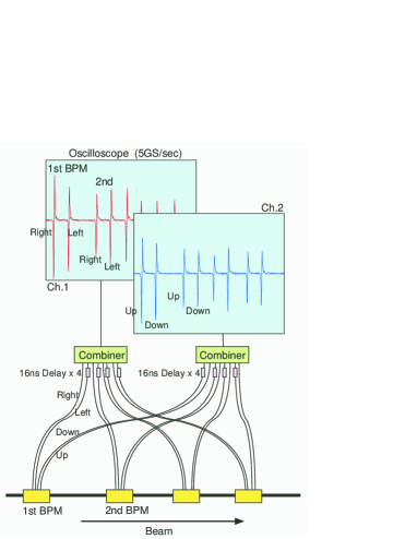
Along the 600-m linac, 90 BPMs are installed and their signals are transferred to one of 18 measurement stations. Signals are delayed and combined so as not to overlap each other, and are fed into a 5-Gs/s waveform digitizer (Sony-Tektronix TDS-680B/C)[6], as in Fig. 1. Although the BPM signal is a fast bipolar, the readout precision is optimized using the interpolation function of the digitizer. All 18 digitizers are triggered by a single distributed signal, which is synchronized with beam repetition and rf frequencies.
The waveform is read through the GPIB, and a signal from each electrode is analyzed with a predetermined response function once per second by a VME computer (Force 68060). The response functions include 3rd-order position-mapping functions, attenuation factors of various components and position offsets against the center of the corresponding quadrupole magnet derived from a beam-based alignment.
Since the timing and amplitude ranges of BPM signals are different depending on the beam modes and locations, the process is driven by a control database system[7].
The acquired beam positions at 18 stations are sent to central computers once per second and are served for various beam-energy and orbit feedback systems to maintain stable beam operation.
3 TWO-BUNCH OPERATION
The BPM system was improved for two-bunch operation.
3.1 Improvements to BPM System
As written above, it is important to acquire the beam positions of two bunches along the linac simultaneously to study the beams. In our instrumentation, signals from those two bunches appear as two signals separated by 96.29 ns on the waveform. Although it was sometimes necessary to add more delay lines so as to avoid waveform overlapping, there was no need to add any specific hardware to handle such signals with small separations.
The calibration factors were re-examined since delay lines were added, and the beam-timing database for the signal analysis was extended to accommodate two-bunch information.
Processing functions/commands for BPMs on the central computers are also extended or added for two bunches, while keeping the old functions as before for single-bunch operations.
With these modifications, the BPM processing system was extended for two-bunch operation without any performance loss in either precision and speed. It has been used in beam operation since March, 2001.
3.2 Operation Software with BPM
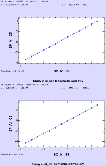
Most of the operation software which utilize the BPM information was extended to meet both single- and two-bunch operations. One of such examples is Fig. 2, which measures the beam energies of two bunches by correlation between a steering-magnet field and the beam-position response at the bunching section.
3.3 Two Bunch Controls
In order to accelerate the beams properly, the beam characteristics of two bunches need to be adjusted so as to be the same. For example, in order to adjust the beam-energy differences, we change the beam timing and rf pulse timing. The beam timing can be changed by 10-ps steps[4] and the rf pulse timing can be changed by 1.75-ns steps at each sector independently. Most of other parameters in the linac are not sensitive against time separation of 96.29 ns.
With such adjustments, the 10-nC primary electron bunches are accelerated up to 3.7 GeV and positrons are generated as shown in Fig. 3.

3.4 BEAM FEEDBACK LOOPS
The beam feedback loops in the linac for energy and orbit stabilization[2] were also extended to control two-bunch beams. Since we don’t have many mechanisms to control two bunches independently, most feedback loops were modified to use positions derived from the charge-weighted averages of two bunches. With these changes, those loops can maintain the average orbit and energy. In software, only the monitoring function was extended to read the average positions if two bunches are accelerated. For positron injection, about 20 beam feedback loops are used, and they are all extended for two bunches.
While normal energy and orbit feedback loops use charge-weighted average positions, feedback loops to minimize the energy differences use the position difference between two bunches, as shown in Fig. 4.

Although the energy difference does not change frequently, such loops stabilize the beam over the long term.
4 SUMMARY
The data-acquisition system for the linac BPMs was upgraded to provide beam positions in two-bunch operation without losing any original features. Along with improvements of the streak camera and wire scanner systems, it has still been indispensable to study and operate on linac beams. The system is also used by many operation software programs, including beam-energy and orbit feedback systems.
References
- [1] K. Furukawa et al., “Beam Switching and Beam Feedback Systems at KEKB Linac”, Proc. of LINAC2000, Monterey, USA., 2000, p.633.
- [2] K. Furukawa et al., “Energy Feedback Systems at KEKB Injector Linac”, Proc. of ICALEPCS99, Trieste, Italy, 1999, p.248.
- [3] K. Furukawa et al., “Towards Reliable Acceleration of High-Energy and High-Intensity Electron Beams”, Proc. of LINAC2000, Monterey, USA., 2000, p.630.
- [4] S. Ohsawa et al., “Increase of Positrons by High-intensity Two-bunch Acceleration Scheme at the KEKB Linac”, to be published in Proc. of PAC2001, Chicago, USA., 2001.
- [5] Y. Ogawa et al., “Two-Bunch Operation of the KEKB Linac for Doubling the Positron Injection Rate to the KEKB Ring”, to be published in Proc. of APAC2001, Beijing, China, 2001.
- [6] T. Suwada et al., “Stripline-Type Beam-Position-Monitor System for Single-Bunch Electron/Positron Beams”, Nucl. Instr. and Meth. A440 (2000) 307.
- [7] N. Kamikubota et al., “Data Acquisition of Beam-Position Monitors for the KEKB Injector-Linac”, Proc. of ICALEPCS99, Trieste, Italy, 1999, p.217.