WEAP038 CONTROL SYSTEM DESIGN FOR THE LIGO PRE-STABILIZED LASER
Abstract
To meet the strain sensitivity requirements [1], [2] of the Laser Interferometer Gravitational Wave Observatory (LIGO), the laser frequency and amplitude noise must initially be reduced by a factor of 1000 in the pre-stabilized portion of the interferometer [3]. A control system was implemented to provide laser noise suppression, data acquisition interfaces, diagnostics, and operator control inputs. This paper describes the VME-based analog and digital controls used in the LIGO Pre-stabilized Laser (PSL).
1 INTRODUCTION
Gravitational waves, the ripples in the fabric of space-time, were predicted by Einstein’s General Theory of Relativity. Although astronomical observations have inferred the existence of gravitational waves, they have yet to be detected directly. The Laser Interferometer Gravitational-wave Observatory (LIGO) is one of the large-scale gravitational-wave detectors currently being built worldwide.
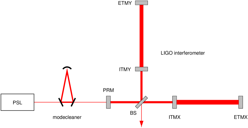
The Pre-stabilized Laser (PSL) subsystem is the light source for the LIGO detector as shown in Figure 1. The output of the PSL is modematched into the suspended modecleaner before being coupled into the LIGO interferometer. The term pre-stabilized is used because the laser undergoes two stages of stabilization prior to being injected into the interferometer.
The 10-W laser used is configured as a master-oscillator-power-amplifier (MOPA), with a 700 mW single-frequency, single-mode non-planar ring oscillator used as the master oscillator. The control strategy uses the actuators of the master oscillator in order to stabilize the frequency. Power stabilization is achieved by control of the power amplifier output.
2 HIGH-FREQUENCY INTENSITY NOISE SUPPRESSION
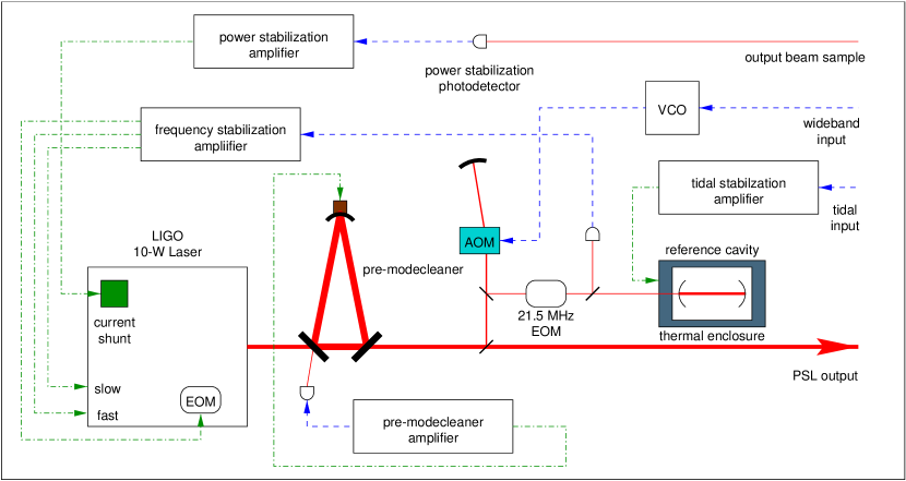
The PSL topology is shown in Figure 2. Light from the laser is modematched into a high-throughput, ring Fabry-Perot cavity called the pre-modecleaner (PMC). The PSL has a design requirement that the output be close to the shot-noise limit for 600 mW of detected light at the interferometer modulation frequency of 25 MHz. As this is beyond the bandwidth of any electronics servo, it is done by passive filtering by the PMC. By appropriate choice of mirror reflectivity, the PMC acts as a tracking bandpass filter with a pole at the cavity half-bandwidth. One of the PMC mirrors is epoxied to a piezoelectric transducer (PZT) to vary the length of the cavity. The servo electronics constantly adjusts the PZT voltage in order to keep the incident light resonant with the cavity.
3 FREQUENCY STABILIZATION
Astrophysical models suggest that in order to plausibly detect candidate gravitational-wave sources, the LIGO detector must achieve a displacement sensitivity of better than 10-19 at 100 Hz. This corresponds to a frequency noise of 10-7 at 100 Hz.
3.1 Actuators
The frequency stabilization servo utilizes three frequency actuators inside the 10-W laser. A thermo-electric cooler (TEC) bonded to the laser gain medium actuates on the laser frequency by thermally changing the optical path length. DC–1 Hz adjustments to the laser frequency are made with the TEC. This actuator, modeled as three poles at 0.1 Hz, has a coefficient of 4 GHz / V and is used for large scale adjustments to the laser frequency. Also bonded to the laser gain medium is a PZT, which covers DC–10 kHz. A voltage applied to the PZT stresses the laser medium and induces refractive index changes to change the laser frequency. The PZT has a flat response to 100 kHz and is known to have a number of mechanical resonances beyond 100 kHz. Fast frequency fluctuations beyond 10 kHz are handled by the third frequency actuator, a Pockels cell located between the master oscillator and power amplifier.
3.2 Implementation
A small fraction of the output of the PMC is sampled and frequency shifted through an 80 MHz acousto-optic modulator (AOM). The output of the AOM is focussed into a phase modulator that imparts sidebands at 21.5 MHz. The output of the phase modulator is then modematched into a high-finesse, linear Fabry-Perot cavity which is used as a frequency reference against which the laser frequency is stabilized. The frequency stabilization scheme employs the well-known Pound-Drever-Hall technique in which the light incident on the reference cavity is phase-modulated [4]. Both the carrier and sideband light reflected from the reference cavity is focused onto a tuned photodetector. The output of the tuned photodetector is bandpass filtered and synchronously demodulated to derive the error signal.
In order to ensure closed-loop stability, the open-loop gain of the PZT actuator must be well below that of the Pockels cell at the PZT mechanical resonance frequency. To ensure this, the PZT actuator path is aggressively rolled off after the designed 10 kHz crossover. In the absence of the Pockels cell, the PZT path is naturally unstable at 15 kHz. With a dynamic range some 30 times greater than that of the Pockels cell, a self-sustaining oscillation may arise if saturation occurs in the Pockels cell path. Limiting the dynamic range of the PZT actuator prevents this instability.
4 INTENSITY STABILIZATION
Photons in the laser light induce a source of noise in the interferometer known as radiation pressure noise. This noise arises from the momentum imparted to the mirrors as statistically different numbers of photons reflect off the mirrors in the interferometer. To minimize the movement of the interferometer mirrors due to radiation pressure, the intensity fluctuations of the laser must be stabilized to the level of 10-8 1 / .
4.1 Actuator
Currently in the prototype design phase, the intensity servo utilizes a current shunt for fast regulation of the power amplifier pump diode current. Placed in parallel with the power amplifier pump diodes, the current shunt was designed to carry 250 mA.
4.2 Implementation
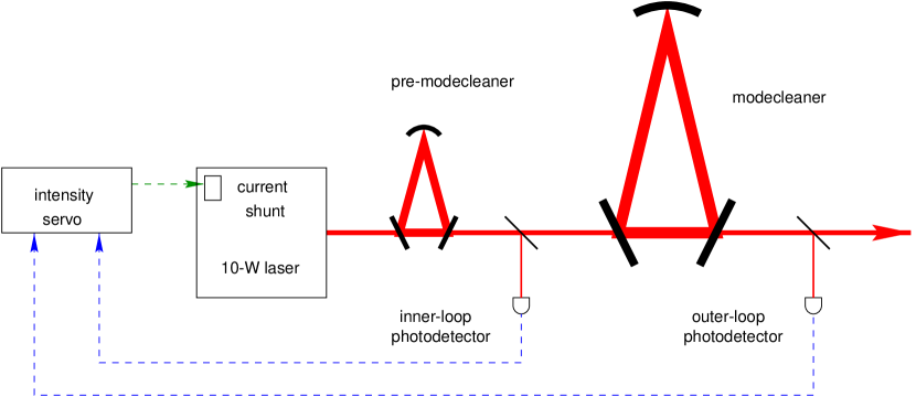
The intensity stabilization servo adopts a dual-loop topology as illustrated in Figure 3. Inputs from photodetectors located after the PMC and modecleaner are used in either a single or dual sensor configuration. In the single sensor configuration, the outer-loop photodetector provides the signal to the servo electronics. In the case where the modecleaner is not locked, the single-sensor signal comes from the inner loop photodetector. In the dual sensor case, both the inner and outer feedback paths provide signals to the servo electronics.
In the dual loop configuration, noise suppression is established in two phases. Closing the inner loop yields a high-bandwidth, well-behaved inner loop with partial noise suppression. The outer loop is then closed around the inner loop to provide the balance of the noise suppression.
5 DATA ACQUISITION AND USER CONTROL
The user control and interface is via the Experimental Physics and Industrial Control System (EPICS). Through EPICS the operator can remotely monitor the performance of the PSL and adjust the various servo loop gains and settings. The operator interface is a series of graphical screens, that indicate the current status of the PSL. Processing the data and events is the input / output controller (IOC), a Baja4700E MIPS-based processor running the vxWorks kernel. The IOC performs the real-world input/output tasks and local control tasks, and provides status information through the Channel Access network protocol.
The control software for the PSL is event-driven and is written in state notation language. Although not fully debugged, automated operation from cold start through to full operation has been demonstrated. One software routine constantly adjusts the TEC on the 10-W laser to keep the laser frequency well within the dynamic range of the PZT. One consequence of this is that lock re-acquisition is instantaneous once the cause of the loss of lock is removed.
At present a dozen signals are acquired and logged through the LIGO data acquisition system. Fast signals are acquired at the rate of 16 kHz whilst slower signals are acquired at 256 Hz. All signals are recorded and logged.
6 ACKNOWLEDGEMENTS
We thank the entire LIGO team for assistance and support. This work is supported by the National Science Foundation under cooperative agreement PHY–9210038.
References
- [1] Alex Abramovici et. al., “LIGO: The Laser Interferometer Gravitational-Wave Observatory”, Science, 256, 325, April (1992).
- [2] A. Lazzarini and R. Weiss, “LIGO Science Requirements Document (SRD)”, internal LIGO document E950018-02-E.
- [3] P. King, R. Savage and S. Seel, “(Infrared) Pre-stabilized (PSL) Design Requirements”, internal LIGO document T970080-09-D.
- [4] R. W. P. Drever et. al., “Laser phase and frequency stabilization using an optical resonator”, Appl. Phys. 31, 97, (1983).