TUAP050 CORRECTOR POWER SUPPLIES WITH A DAC RESOLUTION UP TO 24 BITS BASED ON 16 BIT DAC DEVICES††thanks: Funded by the Bundesministerium für Bildung, Wissenschaft, Forschung und Technologie (BMBF) and the Land Berlin
Abstract
At BESSY the standard 16 bit resolution of the corrector power supplies was insufficient for the continuous orbit drift correction [1]. A new sophisticated design of the analog/digital I/O board [3] increases the resolution of the analog output up to 24 bits without suffering on losses in the long term stability or the dynamic range of the correctors. This is achieved by a cost-efficient board design using standard 16 bit DAC devices in a range-overlapping fine/coarse architecture.
1 INTRODUCTION
The third generation light source BESSY II started operation
equipped with power supplies using low thermal drift 16 Bit DAC
devices. First experiences with the implemented SVD based automatic
orbit correction scheme showed that the 16 bit resolution of the power
supplies was not sufficient to correct the orbit without unacceptable
influences to specific experiments[1].
A typical solution to solve this problem is to reduce the dynamic
range of the correctors. A single bit of the DAC device then
represents a smaller current step of the corrector power supply
output. The obvious disadvantage of this solution is that large kicks
and bumps are not achievable. This leads to an inacceptably restricted
use of the power supplies for diagnostic and recalibration purposes.
To avoid the disadvantages of a reduced dynamic range a new I/O
board with an increased DAC channel resolution of up to 24 bits
has been introduced.
2 24 BIT DAC BOARD DESIGN
2.1 Compatibility Demands
At BESSY the power supplies are CAN bus controllable. Therefore an I/O
board, together with a piggy back embedded controller including the
CAN bus interface, is plugged directly into the power supply. This
board combination provides the whole functionality needed for low
level control of a typical power supply[3].
Taking this into account, a new 24 bit I/O board, ADA2x16-IO8, has been developed111The design, development and production of this board has been performed by the EuKontroll GmbH, Berlin, Germany. For detailed information please contact Georg v. Egan, EuKontroll@t-online.de. The design has the same form factor as the former 16 bit I/O board. The new board is fully compatible to the former design and consists of:
-
•
8 digital inputs and 8 digital outputs
-
•
a 24 bit analog output
-
•
a fast 16 bit flash ADC, multiplexed to 4 inputs
-
•
a slow dual slope 15 bit sign ADC, multiplexed to 4 inputs
-
•
a connector to house the BESSY embedded controller including a CAN bus interface
-
•
a configurable bus interface unit supporting several bus types (e.g. ISA96, VME)
2.2 Analog Output Stage Design
The long term stability of the corrector power supplies directly affects the static orbit stability of the BESSY II storage ring. This requires a high stability analog stage with low thermal drifts (in our case typically 1.5 ppm / ∘C or better) for the I/O board. The long term stability depends mainly on the drift of the voltage reference and the DAC output. The significant differences in thermal drifts of typical DACs available on the market are shown in Table 1.
| PCM1704 | AD7846 | |
| Audio DAC | Monolithic DAC | |
| 24 bit | 16 bit | |
| Gain Error | 3 % FSR | 0.05 % FSR |
| Bipolar Zero | 1 % FSR | 0.024 % FSR |
| Error | ||
| Gain TC | 25 ppm FSR / ∘C | 1 ppm FSR / ∘C |
| Zero TC | 5 ppm FSR / ∘C | 1 ppm FSR / ∘C |
| FSR = full scale range, TC = temperature coefficient | ||
Because long term stability of the power supplies is a key feature to achieve a sufficient static orbit stability, the design of the 24 bit DAC board is based on a combination of two low thermal drift 16 bit DAC devices. A range-overlapping architecture is used to accomplish the 24 bit resolution (see Figure 1). The 16 bit DAC devices are the same as in the design of the 16 bit board. The higher 8 bits of DAC1 are used for coarse setting and the 16 bits of DAC2 for fine setting. The lower 8 bits of DAC1 are available to linearize the relative accuracy or endpoint nonlinearity of the 24 bit output if needed (in our case this feature is not used).
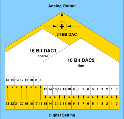
Critical in this design is the transition point between the two 16 bit DAC devices (e.g. bit 16 switches to one and bits 0..15 are switching to zero). This directly affects the differential nonlinearity and therefore the monotonicity of the design. In our case the board is calibrated to provide monotonicity up to 17 bits resolution. Considering a full scale range of 10 V a single bit of 24 bit resolution represents 1.192 V and 17 bit represents 152.59 V; i.e. the design is calibrated to be monotonic for relative settings down to 152.59 V or better.
2.3 Measurements
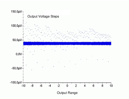
Figure 2 shows the measured relative output steps of
one randomly selected 24 bit DAC when the input is incremented by
steps of 25 digits, which is equivalent to a 19 bit operation
mode. In the ideal case of a 19 bit operation mode, every relative
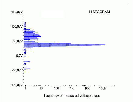
output step of the DAC should be 38.15 V. In Figure
3 the majority of measured
output steps are in the 38.15 V region and only some few are in
the 152.59 V region.
Because of these encouraging measurement results we expected significant
improvements regarding the resolution of the corrector power supplies
and therefore performance improvements of the orbit correction
scheme.
3 PERFORMANCE
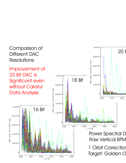
After installation of the ADA2x16-IO8 24 bit DAC boards, first tests with the SVD based orbit correction scheme have been done using different resolutions for the setting. Figure 4 shows the FFT performed over the resulting time dependent vertical beam position data of all beam position monitors (BPMs). A drastically reduced orbit drift could be seen when the resolution was increased from 16 bit to 18 resp. 20 bit [2].
4 CONCLUSION
The new 24 bit design of the analog/digital I/O board provides the higher resolution needed for the correctors of the third generation light source BESSY II. Due to the range-overlapping architecture of the board using the low thermal drift 16 bit DAC devices, the known static orbit stability is guaranteed even without active orbit correction. Applying a SVD based orbit drift correction algorithm the closed orbit is now being corrected with a stability of typically 1..2m.
References
- [1] Orbit Control at BESSY II, R. Bakker, K. Holldack, R. Müller, P. Kuske:BESSY, EPAC 2000, Vienna, Austria, p. 666
- [2] Orbit Drift Correction Using Correctors with Ultra-High DAC Resolution , K. Bürkmann, R. Bakker, F. Falkenstern, J. Feikes, B. Franksen, R. Görgen, P. Kuske, R. Lange, I. Müller, R. Müller, J. Rahn, T. Schneegans:BESSY, PAC 2001, Chicago, USA
- [3] CAN: a Smart I/O System for Accelerator Controls, J. Bergl, B. Kuner, R. Lange, I. Müller, G. Pfeiffer, J. Rahn, H. Rüdiger:BESSY , ICALEPCS 1997, Beijing, China, p. 292