Kerr-lens mode-locked lasers as transfer oscillators for optical frequency measurements
Harald R. Telle, Burghard Lipphardt and Jörn Stenger
Physikalisch-Technische Bundesanstalt, Bundesallee 100, 38116 Braunschweig, Germany
We introduce a novel concept for optical frequency measurement and division which employs a Kerr-lens mode-locked laser as a transfer oscillator whose noise properties do not enter the measurement process. We experimentally demonstrate, that this method opens up the route to phase-link signals with arbitrary frequencies in the optical or microwave range while their frequency stability is preserved.
PACS numbers: 42.62.Eh, 06.20.Fn, 06.30.Ft
1. Introduction
Continuous-wave mode-locked lasers emit a periodic train of short pulses. The spectrum of this emission corresponds to a comb of distinct lines with well-defined spacing if the mode-coupling mechanism is sufficiently strong and fast. It has been shown that the non-resonant, electronic Kerr-lens mode-locking (KLM) process can satisfy this requirement [1], making such lasers highly suited for optical frequency measurements [2], [3], [4]. The frequency of any line of the spectral comb emitted by such a KLM laser is given by an integer order number , the pulse repetition frequency and a so called carrier-envelope offset-frequency , which accounts for the offset of the entire comb with respect to the frequency zero:
| (1) |
When all three quantities are known, any unknown external optical frequency within the span of the comb can be absolutely measured by detection of its beat-note frequency with a suitable comb line.
Absolute frequency measurement means that is measured and expressed in terms of SI-Hertz. This primary unit is realized by a Cs-clock controlled radio frequency (rf) source, which is a H-maser generating a standard frequency of 100 MHz in our case. Thus, no frequency measurement can be better in fractional frequency instability than that of the rf-reference. However, optical frequencies are measured in many cases with respect to an optical reference frequency by measurement of their frequency difference [1]. Then, only a fraction of the H-maser noise enters the measurement process, given by the ratio between the frequency difference and the absolute frequency.
The limitation due to the H-maser noise can be overcome by measurement of frequency ratios rather than frequency differences whenever oscillators with better noise properties than the H-maser are to be compared. A frequency ratio is unitless, i.e. there is no need to refer to the unit Hertz, and thus the frequency noise properties of the oscillators involved can be preserved when building the ratio. We will demonstrate below, that, in fact, optical frequency ratios can be measured with much smaller instabilities than that of the H-maser.
An important issue for such measurements is the frequency noise of the KLM laser due to technical perturbations. Conventional approaches [5] attempt to stabilize both the group and phase delay of the laser resonator by piezo transducers. However, as a result of the finite response time of these elements, the servo bandwidth of such servo loops is typically not sufficient to reduce the frequency noise of the beat-note to a level below the noise of the optical signal at . For the same reason, it is very difficult to reduce the fractional frequency noise of to levels below that of the microwave reference, at least at high Fourier frequencies. As a consequence, the short-term instability of those measurements is limited by the mode-locked laser and long averaging times are required for measurements with low uncertainties.
Our novel approach completely differs in handling the technical frequency fluctuations of the KLM laser. We generalize the transfer oscillator concept [6], which relates signals with integer frequency ratios, to signals with rational frequency ratios. Here, the laser is only slowly frequency stabilized while all beat-notes are phase-tracked with fast phase-locked loops (PLL) and online processed with analog electronics. Thus, we are not any more limited by the inertia of the mirror transducers but can make use of the large signal-to-noise ratios of our beat notes which allow for wide servo bandwidths and thus small residual error signals. As a result, the additive noise of the measurement process becomes substantially smaller than the frequency noise of the signals involved and can be neglected. This novel concept, which compensates the noise of the mode-locked laser will be named transfer concept in the following. It will be applied to the measurement of frequency ratios between various frequency standards: a diode laser at 871 nm, a Nd:YAG laser at 1064 nm, a dye laser operating at 657 nm and a 100 MHz reference signal from a H-maser.
2. Elastic tape picture and transfer concept
We integrate Eqn. (1) to relate the instantaneous phases of all signals,
| (2) |
where , , and denote the instantaneous phase angles of , , and , respectively. The integration constant accounts for the dispersion properties of the optical components involved. It is assumed to be constant or only slowly time-varying. This ansatz is motivated by the fact, that the fast electronic Kerr effect in KLM lasers tightly couples almost instantaneously all modes of the comb. In other words, any individual mode is injection-locked by a strong input signal resulting from the superimposed modulation side-bands of the other modes. Thus, one expects that the quantum-limited carrier frequency noise is determined by almost the total laser power, similar to the Schawlow-Townes limit of a single frequency laser. In this sense, the KLM laser oscillation can be considered as one spectrally extended super-mode. Given the validity of Eqn. (2), frequency fluctuations of this super-mode resulting from technical perturbations can be expressed by various pairs of orthogonal components, e.g.
-
A.
common mode fluctuations, i.e. fluctuations of the mean of the group- and phase delay of the laser resonator while the ratio of both quantities remains constant and
-
B.
fluctuations of the difference of these quantities while one of them, e.g. the phase delay, is held constant.
This behaviour can be visualized as an elastic tape labelled with a scale of equidistant spectral lines which is randomly stretched while it is held fixed at a characteristic point on the frequency scale. This fixed frequency characterizes the specific type of technical noise. In case A whereas is found in the optical carrier frequency region, , in case B. For acoustic vibrations of resonator mirrors, as an example, we find a fractional change of the phase delay :
| (3) |
where is the cavity length, the length of the gain medium and its phase-index of refraction. The refractive index of the air and possible other intra-cavity elements have been neglected in Eqn. (3). The corresponding expression for the fractional change of the group delay reads
| (4) |
The fixed point frequency is found
| (5) |
For the parameters of our laser, we obtain
| (6) |
This frequency is small compared to the carrier frequency of a few hundred THz. Thus, cavity length fluctuations represent case A to good approximation. As a consequence the comb offset frequency , which is by definition a frequency close to zero, is only weakly affected by such fluctuations. Fixed point frequencies of other types of fluctuations can be estimated in a similar manner. For example, temperature changes of the gain medium lead to a change of its physical length, a change of the phase index and a different change of the group index. We estimate a fixed point frequency of
| (7) | |||
| (temperature variation of gain medium) |
for the parameters of our laser.
As another specific perturbation, tilting of the cavity mirror behind the double-prism arrangement [7], is of particular interest. The cavity length is not affected for a specific carrier frequency but owing to the lateral spectral spread of the laser mode at this position, the group delay is strongly changed by such tilting. This type of fluctuation corresponds to case B. It can be used to actively control , whereas cavity length control is suited to stabilize the optical carrier frequency. It follows from the elastic tape picture, that technical noise contributions from the frequency comb are completely known if the phase angles of two distinct comb lines are monitored as a function of time. Two candidates which naturally come to mind are and an arbitrary line at within the span of the comb. The latter has to be measured with respect to a stable optical reference frequency at , i. e. by measurement of the beat-note frequency . We will assume that the signal-to-noise ratios of both the and beat-notes are sufficient to yield an rms-phase error of radians within a bandwidth which is sufficient to track technical fluctuations of and . Cycle-slipping can be excluded under such conditions. Then, both and are unambiguously known and so are the instantaneous phase angles of all other comb lines, according to Eqn. (2). This feed-forward technique for phase angles is the key element of the transfer concept. In the following, we present two applications of this method.
3. Linking optical and microwave frequencies
The first application deals with the frequency modulation (FM) noise analysis of a microwave signal if an optical signal with frequency is available which shows superior FM noise properties. The scheme is shown in Fig. 1. Here, three input signals are detected by photo diodes:
-
i.
the beat note between the external signal at and the nearest comb line,
-
ii.
the pulse repetition frequency , and
-
iii.
the carrier-envelope-offset frequency .
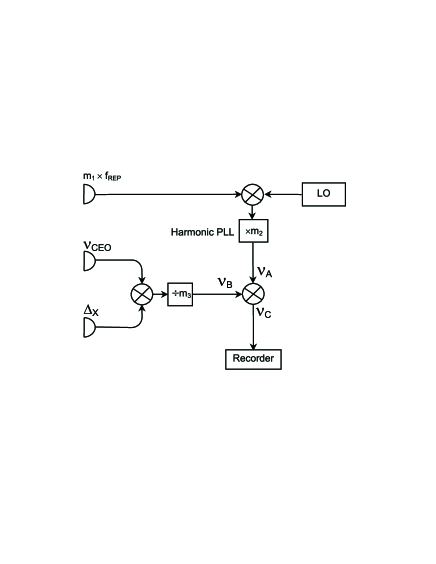
The detection of requires one or more additional nonlinear processes [8]. The simplest case is applicable if the comb covers a frequency ratio of more than a factor of two, i.e. one octave. Then, the comb lines at the low frequency comb wing are frequency doubled to yield a beat note of their second harmonics with the lines at the high frequency comb wing. All comb lines contain one according to Eqn. (1) but the second harmonics contain two . Thus, the beat note oscillates at providing the desired input signal. If all three signals are available, one has to select an order number which can be separated into three factors, each of the order of . This can be accomplished choosing a proper value of . Then, the frequency of the microwave local oscillator (LO) is mixed with a harmonic of the pulse repetition frequency as detected by a photo diode to yield an rf-signal at frequency . This frequency is further multiplied by a factor of with the help of a harmonic PLL yielding
| (8) |
In a second channel, the sum frequency of and is divided by . This leads to a signal at frequency
| (9) |
Subtracting both frequencies with the help of a mixer, as shown in Fig.1, results in
| (10) |
However, the elastic tape formula (1) predicts for the expression in the bracket
| (11) |
and thus
| (12) |
Note that the signal at is independent of the noise properties of the KLM laser, i.e. the laser acts as a true transfer oscillator, bridging a frequency ratio of . Since the phase angles of all signals are processed according to Eqn. (2), can be considered as the frequency of the beat-note between the th harmonic of and the th sub-harmonic of .
4. Linking two optical frequencies
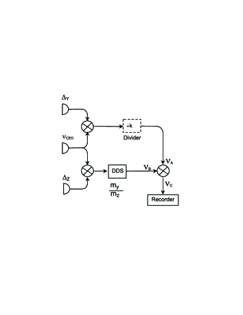
The second application of the transfer concept deals with the FM-noise measurement of an optical signal with frequency if an optical reference is available which has superior noise properties but oscillates at a very different frequency , as shown in Fig. 2.
As before, we apply the elastic tape picture, which leads to
| (13) |
and
| (14) |
The beat signal at is mixed with the -beat signal which leads to
| (15) |
if we neglect the optional frequency divider for the moment. The sum frequency of and , on the other hand, is processed with a direct-digital-synthesis IC (DDS). Such a device is capable of generating an output signal from an input clock signal with a frequency ratio given by a long digital tuning word while the input-to-output frequency agility is preserved. The latency time of these devices, i.e. the time required to set a new tuning word, is not a problem in our case, since the tuning word is chosen once and then held fixed. The DDS numerically approximates the ratio of two integers by , where is an integer and the bit-length of the tuning word. As discussed below, the resulting error is negligible for bit or 48 bit in our case, where the integers and are of the order of . As a result of this signal processing, one obtains
| (16) |
Generating the difference frequency between both signals as before and using Eqns. (13) and (14), we find
| (17) |
which is again independent of the properties of the KLM laser. Since the phase angles of all signals are processed according to Eqn. (2) as above, can be considered as the frequency of the beat-note between and as projected to the vicinity of .
5. Experimental
The setup of our Kerr-lens mode-locked Ti:Sapphire-laser is similar to [9], employing a combination of prisms and double chirped mirrors for compensation of group velocity dispersion. A similar, external prism pair is used for pulse re-compression. The pulse duration is fs (FWHM) while the output spectrum typically spans 70 THz (FWHM), centred at about 790 nm. The pulse repetition frequency is about 100 MHz. Approximately 30 mW of the laser output is coupled into a 10 cm long piece of air-silica microstructure (MS) fiber with a core diameter of 1.7 m and a zero-GVD wavelength of 780 nm [10]. The output spectrum of the fiber extends from about 500 nm to about 1100 nm. The carrier-envelope-offset frequency is measured by second-harmonic-generation of the comb’s infrared portion around 1070 nm in a nonlinear-optical crystal (LBO). The beat-note between the resulting green SHG signal and the green output of the MS fiber is detected by a photo multiplier (PM) after spectral and spatial filtering both fields with a single mode fiber and a 600 l/mm grating, respectively.
As frequency references in the optical range, we use three different signals,
-
i)
the sub-harmonic at 344 179 449 MHz (871 nm) of the output of a single Yb+-ion frequency standard [11],
-
ii)
the output of a Nd:Yag laser at 281 606 335 MHz (1064 nm) which is frequency-stabilized via saturated absorption of its second harmonic in I2 vapour, and
-
iii)
the output of a dye-laser that is frequency-stabilized to the Ca intercombination line at 455 986 240 MHz (657 nm) [12].
All three frequencies have been previously measured with respect to a Cs atomic clock [2], [3], [13], [14], [15]. However, these absolute values are not important for the purpose of this paper, which aims to demonstrate a novel measurement and synthesis principle. The sources of the signals at 344 THz, 281 THz and 455 THz will be referred to as Yb-, Iodine- an Ca-standard in the following (index Yb, Iod and Ca).
The Yb-standard was employed both for the microwave-to-optical and the optical-to-optical link. The pulse repetition frequency of the laser was set to a value close to 100 MHz which resulted in a mode number = 3 441 024 for the mode closest to . As discussed above, this number must be divisible by 3 factors of the order of such as . The pulse repetition frequency was measured with a fast InGaAs photo diode (PD) at 10.3 GHz, i.e. at a harmonic order of . For the sake of dynamic range of the PD we restricted the number of detected harmonic orders to a few using optical pre-filtering in a Fabry-Perot interferometer with a free spectral range of about 10.3 GHz (10 mm thick fused silica etalon). The output signal of the microwave PD was down-converted with the help of a double-balanced mixer and a microwave synthesizer (LO) controlled by a 100 MHz standard frequency from a H-maser. The LO frequency at GHz was tuned to yield a down-converted signal of about 500 kHz. This frequency was multiplied by a factor of with the help of a harmonic PLL. Hence, its output signal at MHz carried the frequency noise of the th harmonic of the pulse repetition frequency and that of the H-maser as multiplied to a virtual frequency of GHz. As described above, the frequency noise of the pulse repetition frequency can independently be deduced from and . Both signals were pre-filtered with PLLs with a servo bandwidth of MHz. As a result of choice of signs, the sum frequency of both ( 70 MHz) carried the desired information. This signal was frequency divided by leading to a signal at kHz which carried the noise of the th harmonic of the pulse repetition frequency and that of the Yb standard as divided to a virtual frequency of THz.
Since , the noise of the pulse repetition frequency was exactly the same in both paths and cancelled out if the frequency difference between and was generated with the help of the last mixer, as shown in Fig. 1, thus realising the transfer principle. As mentioned above, the output of this mixer at MHz can be considered as the beat-note between the H-maser signal as multiplied to 989 GHz and the output of the Yb standard, as divided by 348 to 989 GHz. The signal at was down-converted to about 40 Hz with the help of an rf-synthesizer and a mixer, analog-to-digital converted, digitally recorded and subsequently Fourier-transformed.
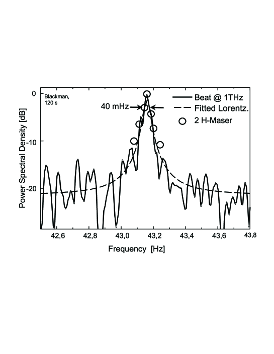
A spectrum of such a 120 s long record is shown in Fig. 3. One finds a 40 mHz wide carrier on top of a much broader line which can not be seen in Fig. 3. Note that this line with a sub-Hertz width was generated from two signals whose frequencies fluctuated by many kHz which demonstrates the effect of the transfer concept. The control bandwidth of the harmonic PLL was set to a few tens of kHz. This resulted, together with the second order characteristic of its loop filter, to a loop gain of dB in the Fourier frequency range shown in Fig. 3. The loop gains were even higher ( dB) for the PLLs which phase-tracked the signals at and . Thus, the sum of the residual servo errors, i.e. the total error of the frequency transfer process, was negligible and Fig. 3 can be considered to represent the true line shape of the H-maser harmonic at 989 GHz since the frequency noise of the Yb signal was also negligible as shown below.
The shape of the spectrum, a narrow line on top of a broad pedestal, was expected from the phase-noise specifications of the H-maser. This broad pedestal becomes dominant and submerges the narrow carrier, if the H-maser signal is further frequency multiplied, e.g. to the optical range. Thus, the short-term instability of a frequency ratio measurement between a H-maser and a quiet optical frequency standard, such as our Yb- or Iodine standards, is expected to be limited by the H-maser noise.
For comparison, the open circles in Fig. 3 show the corresponding beat note spectrum of the outputs of two H-maser as multiplied to a frequency of 989 GHz. It was calculated from a 1000 s record of readings of the timing jitter between 10 MHz standard frequencies generated by both masers. The close agreement with the Yb/H-beat at 989 GHz demonstrates that the frequency multiplication process by a factor of performed by the KLM laser does not deteriorate the H-maser noise properties at Fourier frequencies below 0.1 Hz.
In the following, we describe a second application of the transfer concept, the measurement of an optical frequency ratio. Here, an additional photo diode was used to detect the beat-note at ( MHz) between the comb line with order number and the output of the Iodine-standard. As mentioned above, the sum frequency was processed by the DDS after pre-filtering both signals with fast PLL tracking oscillators (bandwidth MHz) . Since the required multiplication factor was of the order of one, which can not be generated by a DDS chip according to the sampling theory, we used an additional division factor of in both signal paths in Fig. 2. The divider in the Yb-signal path was a conventional TTL divider while in the other path the DDS tuning word was corrected for this value. The DDS (AD9851) was programmed within the resolution of its 32 bit tuning word to generate an output frequency . This was 8.4 mHz lower than the required value . However, multiplication of this amount by 8 and division by 344 THz leads to an relative error of which is negligible compared to other uncertainties. However, for future applications which might require higher precision, this error can be reduced by at least 4 orders of magnitude with a proper correction or with a DDS with 48 bit tuning word.
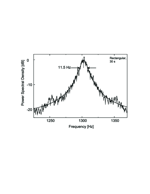
The output of the last mixer in Fig. 2, which was equivalent to the beat signal between the Iodine- and Yb- signals at a virtual frequency of 344/8 THz = 43 THz, was down-converted to the kHz range, analog-to-digital converted and digitally recorded. The Fourier transform of a typical 30 s record is shown in Fig 4. One finds a Hz wide line on top of a pedestal of white additive noise. As in Fig. 3, the PLL’s bandwidths of MHz ensured a negligible residual servo error. Thus, Fig. 4 shows the true power spectrum of a non-integer sub-harmonic of the Iodine signal at 43 THz since the contribution of the Yb signal to the spectrum was not significant, as discussed below.
Finally, we describe a third frequency ratio measurement employing the Yb- and Ca-standards. The mode order of comb line nearest to the Ca frequency was while during all experiments. Here, the Ca frequency was down-converted as opposed to the experiment described above, in which the Iodine-frequency of 281 THz was up-converted to THz. For this reason, the pre-division factor could be reduced to . Consequently, the output of the last mixer in Fig. 2 corresponded to the beat-note between the Yb and Ca signals at a frequency of 344/4 THz = 86 THz.
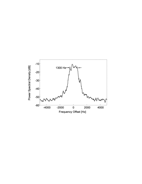
The spectrum in Fig. 5, however, shows the 4th harmonic of this signal as generated by a frequency-quadrupling PLL. Thus, it represent the beat-note at the Yb-frequency which means that the frequency transfer was carried out over a frequency gap of () THz = 111 THz. The width of 1300 Hz found in Fig. 5 was mainly due to low-frequency jitter of the Ca frequency while the line width of the Yb-signal was much smaller. This was proved by resolving a 30 Hz wide resonance line at its second harmonic [3].
As mentioned above, the frequency noise of the beat-note between the Yb- and Iodine-signals is substantially smaller than that of the H-Maser, at least at Fourier frequencies Hz. Thus, a frequency ratio measurement of these two optical signals can be carried out with smaller instabilites than that of an Yb/H-maser frequency ratio measurement, at least for short averaging times. This is demonstrated in Fig. 6.

The dashed curve shows the sqare root of the Allan variance (SRAV) of our H-maser. The data of the frequency measurements of the Iodine and the Yb-standard with respect to this H-maser are shown as triangles and squares, respectively. The SRAV of the Yb-laser qualitatively follows that of the H-maser, which limits the measurement for averaging times from 1 to 100 s. The SRAV of the Iodine -signal is larger than that of the H-maser for s. In fact, frequency comparisons of two of such Iodine standards showed a SRAV of about in this range and thus larger than of the H-maser. The SRAV of a frequency ratio measurement of two optical standards, on the other hand, is not limited by H-maser noise, as shown by circles in Fig. 6. The data depicted by solid circles have been derived from the Yb/Iodine beat signal as obtained from the last mixer in Fig. 2 whereas the open circles have been calculated from , and as counted by totalizing counters (1 s averages). Both data sets reasonably agree in the overlapping range between 1 and 8 s. The SRAV values of this frequency ratio measurement are substantially smaller than the H-maser frequency instability for s. The -dependency of this SRAV function indicates a white frequency noise level of Hz2/Hz at 344 THz which would result in a spectral line width of Hz (FWHM) in good agreement with the direct beat-note measurement as shown in Fig. 4. From Hz at (344/8=43) THz one calculates Hz at 344 THz under the assumption of white frequency noise. This indicates, that the Yb/Iodine-frequency ratio measurement in Fig. 6 was limited by noise of the Iodine-standard whereas contributions from the Yb-signal were negligible due to its narrow line width of Hz.
6. Conclusion
We have demonstrated a novel concept for frequency measurement and synthesis which is capable of phase-coherently linking signals from very different spectral regions in the optical and microwave ranges without introducing additional noise. We have carried out frequency ratio measurements between optical frequencies with short-term instabilities superior to that of a microwave reference. Since the measurement uncertainties were clearly limited by the noise properties of the frequency standards, one may expect an even lower limitation due to noise contributions of the KLM laser if better optical frequency standards become available. The transfer concept opens up new perspectives for future ultra-high precision applications, e.g. measurement of time variations of fundamental constants as soon as appropriate optical frequency standards are available.
We gratefully acknowledge financial support from the Deutsche Forschungsgemeinschaft through SFB407 and contributions by Andreas Bauch, Tomas Binnewies, Nils Haverkamp, Ursula Keller, Harald Schnatz, Günter Steinmeyer, Christian Tamm, and Guido Wilpers in different stages of the experiments. We are also indebted to Robert Windeler of Lucent Technologies for providing us with the microstructure fiber.
6. References
-
[1]
T. Udem, J. Reichert, R. Holzwarth, and T. W. Hänsch; Opt. Lett. 24 881 (1999).
-
[2]
T. Udem, S. A. Diddams, K. R. Vogel, C. W. Oates, E. A. Curtis, W. D. Lee, W. M. Itano, R. E. Drullinger, J. C. Bergquist, and L. Hollberg; Phys. Rev. Lett. 86 4996 (2001).
-
[3]
J. Stenger, Chr. Tamm, N. Haverkamp, S. Weyers, and H. R. Telle; Opt. Lett., in press (2001).
-
[4]
M. Niering, R. Holzwarth, J. Reichert, P. Pokasov, Th. Udem, M. Weitz, T. W. Hn̈sch, P. Lemonde, G. Santarelli, M. Abgrall, P. Laurant, C. Salomon, and A. Clairon; Phys. Rev. Lett. 84 5496 (2000).
-
[5]
D. J. Jones, S. A. Diddams, J. K. Ranka, A. Stentz, R. S. Windeler, J. L. Hall, and S. T. Cundiff; Science 288, 635 (2000).
-
[6]
G. Kramer, B. Lipphardt, and C. O. Weiss, Proc. 1992 Frequ. Contr. Symp., 39 (1992), IEEE Cat. No. 92CH3083-3.
-
[7]
J. Reichert, R. Holzwarth, Th. Udem, and T.W. Hänsch; Opt. Comm. 172 59 (1999).
-
[8]
H.R. Telle, G. Steinmeyer, A.E. Dunlop, J. Stenger, D. H. Sutter, and U. Keller; Appl. Phys. B69 327 (1999).
-
[9]
D. H. Sutter, G. Steinmeyer, L. Gallmann, N. Matuschek, F. Morier-Genoud, U. Keller, V. Scheuer, G. Angelow, and T. Tschudi; Opt. Lett. 24 631 (1999).
-
[10]
J. K. Ranka, R. S. Windeler, and A. J. Stentz; Opt. Lett. 25 25 (2000).
-
[11]
Chr. Tamm, D. Engelke, V. Bühner; Phys. Rev. A61 053405 (2000).
-
[12]
F. Riehle, H. Schnatz, B. Lipphardt, G. Zinner, T. Trebst, and J. Helmcke; IEEE Trans. Instr. Meas. IM48 613 (1999).
-
[13]
A.Y. Nevsky , R. Holzwarth, J. Reichert, Th. Udem, T.W. Hänsch, J. von Zanthier, H. Walther, H. Schnatz, F. Riehle, P.V. Pokasov, M.N. Skvortsov, and S.N. Bagayev; Opt. Comn. 192 263 (2001).
-
[14]
J. Stenger, T. Binnewies, G. Wilpers, F. Riehle, H. R. Telle, J. K. Ranka, R. S. Windeler, A. J. Stentz; Phys. Rev. A. 63 021802(R) (2001).
-
[15]
H. Schnatz, B. Lipphardt, J. Helmcke, F. Riehle, and G. Zinner; Phys. Rev. Lett. 76 18 (1996).