An intense, slow and cold beam of metastable Ne(3s)P2 atoms.
Abstract
We employ laser cooling to intensify and cool an atomic beam of metastable Ne(3s) atoms. Using several collimators, a slower and a compressor we achieve a 20Ne∗ flux of atoms/s in an 0.7 mm diameter beam traveling at 100 m/s, and having longitudinal and transverse temperatures of mK and K, respectively. This constitutes the highest flux in a concentrated beam achieved to date with metastable rare gas atoms. We characterize the action of the various cooling stages in terms of their influence on the flux, diameter and divergence of the atomic beam. The brightness and brilliance achieved are 2.1 s-1m-2sr-1 and 5.0 s-1m-2sr-1, respectively, comparable to the highest values reported for alkali-metal beams. Bright beams of the 21Ne and 22Ne isotopes have also been created.
pacs:
39.25.+k, 32.80.Lg, 32.80.PjI Brightening rare-gas atomic beams
The efficiency with which metastable rare gas atoms can be produced in gas discharge sources is notoriously low, usually only on the order of 10-5 with the highest reported value being 10-3 for helium [1]. Traditionally, therefore, metastable rare gas atomic beams have shown much smaller flux and density than alkali-metal beams. In recent years, several groups [2, 3, 4, 5, 6, 7, 8, 9, 10, 11, 12, 13, 14, 15, 16, 17] have tried to bridge this gap by employing laser cooling techniques [18] to intensify rare gas beams. At the same time, atomic beams could be made slow and monochromatic.
The principle of beam intensification using laser manipulation of atomic trajectories was illustrated by Sheehy et al in a 1990 paper [19]. The essential element in any such scheme is a laser collimator, whose purpose is to increase the solid angle under which atoms can leave the source and still contribute to the beam flux further downstream. This is achieved by cooling the velocity component transverse to the atomic beam axis. The collimator completely determines the maximum gain in beam flux that can be obtained with laser cooling. Without collimation, the flux of atoms through a constant area decreases geometrically with its distance from the source; with collimation, this flux is essentially constant. Collimators for rare gas atomic beams have been employed by several groups [2, 3, 4, 5, 11, 12, 13, 14, 15, 17].
Since transverse cooling takes a certain time and thus a certain transverse distance, laser collimation inevitably leads to large-diameter atomic beams whose density may be rather low despite the increased beam flux. The solution to this, according to Ref. [19], is to focus the beam and re-collimate it at the focal point. This idea was implemented in its purest form by Hoogerland et al [2] who used a separate magneto-optical lens (MOL) followed by a second collimator. Scholz et al [6], Nellissen et al [7] and Schiffer et al [8] developed a magneto-optical compressor (MOC) in which both focusing and collimation occur within the same device. The mayor difference between a MOL and a MOC is the time spent within the device interacting with the laser fields: a compressor is basically a lens with a focal length shorter than the length of the interaction region. In order for the length of the MOC to stay within reasonable limits, laser slowing of the atomic beam [18, 20] between collimator and compressor is necessary. A MOC device has since been applied to rare gas beams by Buckman and coworkers [10, 11] and by Koolen [3]. Koolen used a lens in combination with a compressor to increase the spatial capture range of the device. Labeyrie et al [16] have also reported on the use of a MOL.
In this paper we describe our solution to brightening rare gas atomic beams, using all the devices mentioned above extended with additional cooling stages. This setup stands out because it produces the highest flux (6 Ne(3s)3P2 atoms/s) in a concentrated beam of any rare-gas atomic beam setup reported to date, comparable even to the brightest available alkali-metal beam [21].
II Experimental Setup
A Overview
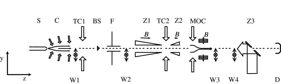
Figure 1 shows a schematic overview of the neon beam line, with five separate laser cooling stages used to create an intense beam of cold atoms. In all cooling stages we use the Ne(3s)P(3p)D3 optical transition at a wavelength nm. Important parameters for this transition are the linewidth MHz, saturation intensity = 42 W/m2 for circularly polarized and = 72 W/m2 for linearly polarized light, recoil velocity mm/s and Doppler temperature = 203K [18].
First, a collimator captures metastable Ne(3s) atoms from a discharge source and collimates them into a parallel beam. Then, an additional transverse cooling stage reduces the divergence of the beam to a few times the Doppler limit. In a Zeeman slower, the atoms are axially slowed to a velocity of ms-1. Again, an additional transverse cooling stage, positioned in between the two solenoids of the slower, reduces the divergence of the slowed atomic beam. Behind the slower, a magneto-optical compressor captures the slowed atoms and funnels them into a narrow beam, which then passes through a hole in a mirror and hits a detector that records the beam flux achieved. The total length of the beam line, taken from the nozzle of the discharge to the beam flux detector, is approximately m.
Table I gives detailed information about the position and length of the different laser cooling stages and the position of detectors. We take the direction along the atomic beam axis.
B Diagnostics
Four sets of wire scanners are positioned along the beam line for diagnostics. A wire scanner consists of a stainless steel wire that can be moved transversely through the atomic beam by a stepper motor. By scanning the wire through the atomic beam and measuring the current due to electrons emitted from the wire, a one-dimensional beam-current profile is generated. The beam profile represents a line-integral over the two-dimensional density distribution of the atomic beam along the length of the wire,
| (1) |
with the Auger detection efficiency of the wire, the elementary charge, and the diameter of the wire. Throughout this paper we use since the exact value of the quantum efficiency of the Auger process for Ne(3P2) atoms on metallic surfaces is not known (Hotop [22] reports for stainless steel); however, is certainly less than 1 so that in this paper we effectively always report a lower limit for the atom flux.
The total flux of metastable atoms in the beam at the position of a wire scanner is found by integrating over the scan direction . By comparing beam profiles taken with two successive scanners, information about the divergence of the atomic beam can be obtained. We calculate the divergence of the atomic beam by dividing the difference in FWHM beam diameters measured with the two wire scanners by their separation, .
Finally, on the way to a trapping chamber where the bright beam can be used, e.g., for collision experiments or to load a magneto-optical trap [23], the atomic beam hits a conducting surface that can be moved in and out of the beam’s path, which we use to measure the total useful atom flux.
C Laser setup
All laser cooling stages are operated from a single continuous-wave single-frequency ring dye laser (Coherent 899-21) with a maximum output power of W when pumped with W of light from an Argon ion laser (Coherent Innova 315). We typically set the dye laser output to 700 mW; this is the output power used for the experiments reported here unless explicitly noted otherwise. The laser is locked to a frequency that is shifted from the Ne (3s) 3P (3p) 3D3 transition by using Zeeman-tuned saturated absorption spectroscopy. This ”global detuning” of the dye laser is normally set at for reasons that will become apparent below. Beams for the various cooling stages are split off by combinations of half-wave plates and polarizing beam-splitter cubes. Two acousto-optic modulators (AOMs) are used to shift the laser frequency for the collimator (80 MHz AOM) and the Zeeman slower (400 MHz). Spherical and cylindrical telescopes are used to expand the laser beams to the required sizes; generally we expand a laser beam such that its FWHM diameters in the - and -directions approximately match the spatial extent of a cooling stage’s interaction region; in this case the edges of the interaction region are irradiated at half the central intensity. Then, 50% of the power falls within the interaction area and the average intensity is 72% of the peak value.
Table I gives details on the laser beam characteristics of each cooling stage.
D Metastable atom source
The beam line starts with a liquid nitrogen cooled source that produces a beam of metastable 20Ne(3s)P2 atoms in a DC discharge that runs through the nozzle of a supersonic expansion. The average axial velocity of the atoms is m/s with a FWHM width of 100 m/s (corresponding to a source temperature of 200 K and a longitudinal beam temperature of 4 K); the center-line intensity for 20Ne(3s)3P2 atoms is s-1sr-1. Other high-energy products emerging from the source are atoms in the metastable 3P0 state, metastable atoms of the isotopes 21Ne and 22Ne, and UV photons.
E Collimator
About 40 mm after the source, the atoms enter the collimator in which they are captured and collimated by a two-dimensional optical molasses [18]. For the molasses beams we use curved wave fronts to achieve a large capture angle while keeping the cooling time as short as possible. To minimize the required laser power, the curved wave fronts are produced by using the zig-zag method as we reported earlier [2]. Linearly polarized laser light is injected at an angle with respect to the plane perpendicular to the atomic beam axis between two 150 mm long, nearly parallel mirrors placed 60 mm apart. With each reflection, is reduced by an amount mrad, half the angle between the mirrors. The Doppler shift experienced by the atoms in the collimator is given by
| (2) |
with and the longitudinal and transverse velocity of the atoms. With the condition the resonant transverse velocity of the atoms is
| (3) |
At the entrance of the collimator this velocity is ms-1 for the experimental parameters we use, i.e., mrad and MHz, resulting in a FWHM capture angle mrad. At the end of the collimator at mm, i.e., after 12 reflections of the laser beam on each mirror, the resonance velocity is reduced to mm m/s. Clearly, this effective detuning at the end of the collimator is too large to provide the lowest possible divergence of the atomic beam; in addition it depends on the axial velocity of the atoms. Therefore, an additional, short, transverse cooling stage is positioned immediately behind the collimator to further reduce the divergence of the atomic beam. Here we use and =0; in-vacuum mirrors create the two-dimensional molasses from a single, linearly polarized laser beam.
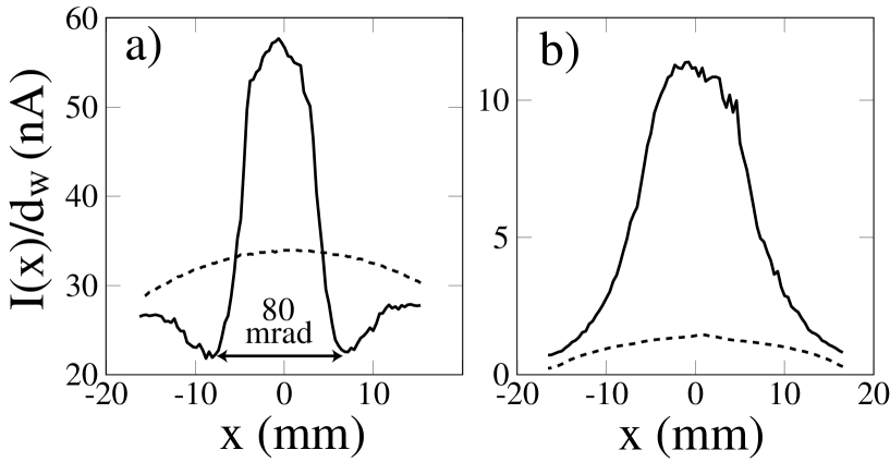
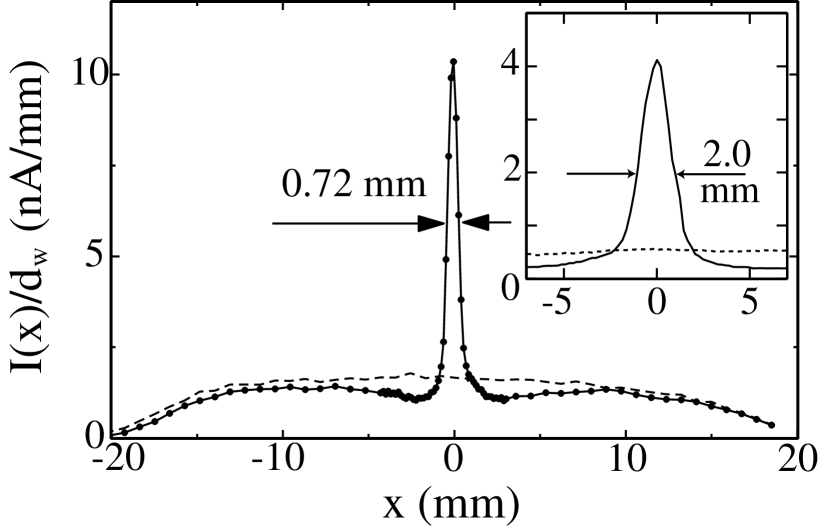
Figure 2 shows experimental beam profiles taken in the direction with wire scanner W1 (which is placed just behind the collimator), and with scanner W2 placed mm further downstream. The effect of the collimator is clearly visible: the atoms are captured and cooled in transverse direction, resulting in an atomic beam with a FWHM diameter of mm containing atoms/s in the 3P2 state. From the figure the capture angle of the collimator is estimated at mrad, approximately the same as found with Eq. (3). The measurements with the second scanner then show a FWHM divergence of the beam of mrad. This value could in principle be reduced further by changing the detuning of the transverse cooling stage; the detuning chosen is a compromise that leads to maximum overall output of the beam machine but which does not necessarily optimize each stage individually (we discuss this further in section III).
Switching the collimation and transverse cooling laser off, the beam flux decreases drastically, as shown by the dashed line in Fig. 2b. This beam profile contains, besides atoms in the 3P2 state, also unwanted products of the source, i.e., atoms in the metastable 3P0 state, metastable atoms of the other isotopes, and UV photons. Therefore a beam stop, consisting of a disc with a diameter of mm, can be positioned in the center of the atomic beam just behind the transverse cooler (see Fig. 1). This beam stop keeps unwanted products (including ground state atoms) from reaching the end of the setup, while most of the laser cooled atoms pass around it, due to the different nature of the trajectories of cooled atoms versus uncooled atoms and UV photons.
F Zeeman slower
The collimated atoms then enter a midfield-zero Zeeman slower [18, 20] in which they are decelerated by a counter-propagating laser beam. The laser beam is coupled in by a mirror positioned in the vacuum behind the magneto-optical compressor (Z3 in Fig. 1). The atomic beam can pass through a 3 mm diameter hole in the center of this ”slower mirror” since the compressor greatly reduces the beam’s radius. The length of the slower is such that 10% of the maximum possible scattering force is sufficient to slow the atoms down. The tapered magnetic field coils (0.85 m and 0.15 m long) are usually set to produce maximum fields of 275 Gauss and -175 Gauss. In combination with the 400 MHz detuning of the circularly polarized slowing laser, this means that atoms with initial velocities up to 500 m/s should be slowed to a final velocity close to 100 m/s.
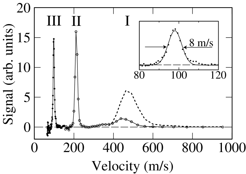
We measured the longitudinal velocity of the atoms leaving the Zeeman slower by a standard time-of-flight technique. Figure 3 shows the measured velocity distribution of unslowed, partially slowed (second Zeeman solenoid operated with reduced current), and fully slowed atoms. As expected, fully slowed atoms have a final velocity of 98 m/s. The measured FWHM width is 8.0 m/s in this case, corresponding to a longitudinal beam temperature of mK.
During the slowing process the divergence of the atomic beam increases due to the reduction in axial velocity as well as the randomness in the direction of the spontaneously emitted photons. To counteract this effect, an additional transverse cooling stage is inserted between the two solenoids of the Zeeman slower. Transverse cooling is possible here because the magnetic field vanishes between the two solenoids. Here we use a simple ”V”-shaped arrangement of two in-vacuum mirrors to create the two-dimensional molasses from a single, linearly polarized laser beam. Reducing the divergence of the atomic beam increases the flux of atoms within the capture range of the magneto optical compressor. We obtain a factor two increase in beam flux behind the MOC in this way.
G Magneto-optical compressor
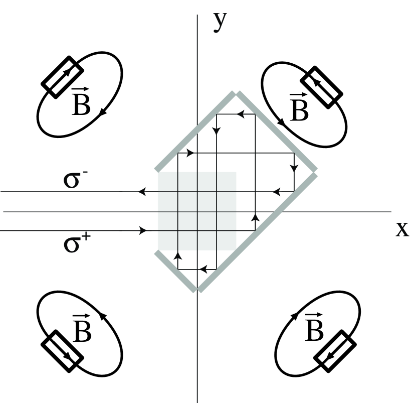
Behind the Zeeman slower, the atomic beam passes through a magneto-optic compressor to reduce its diameter and divergence. Figure 4 shows a schematic view of the device, which is basically a two-dimensional magneto-optic trap where the magnetic field gradient increases along the symmetry axis. Scholz et al [6] have given a description of the motion of atoms inside a MOC.
Two pairs of laser beams are produced by bouncing a single laser beam on a set of in-vacuum mirrors. Atoms interact over a distance of mm with the laser beams, whose average on-resonance saturation parameter is while the detuning .
The magnetic quadrupole field of the MOC is generated by four permanent magnets mounted outside of the vacuum system near the end of the mirror arrangement. The NdFeB magnets have dimensions 606030 mm3 and a magnetization of 1.15 T. At the entrance of the MOC a -metal shield helps to reduce the quadrupole field gradient to T/m, which increases to T/m at the end of the MOC. Given the initial field gradient and laser detuning, an initial resonance circle with radius =10 mm exists within which all atoms will be captured and funneled to the beam axis. Here, is the Bohr magneton.
Figure 5 shows beam profiles measured with the vertical wire of the third and fourth wire scanners. The effect of the MOC is very visible: atoms are molded into a narrow beam with a diameter of mm and a divergence of 8 mrad, containing atoms/s. This results in a particle density of cm-3. From the figure it is also clear that many of the slowed atoms arrive outside the capture range of the MOC and cannot contribute to the flux of the compressed beam.
The measured FWHM divergence m/s approximately corresponds to the FWHM transverse Doppler velocity m/s, resulting in a transverse beam temperature K. One might expect the transverse temperature to be lower than this value, since sub-Doppler cooling is possible when atoms are sufficiently near the beam axis at the end of the MOC [8]. We have found, however, that the final divergence is limited to approximately the Doppler value by a Stern-Gerlach effect. After the atoms exit the compressor’s interaction region, they still have to traverse a large quadrupole field which exerts a force [3]
| (4) |
directed transverse to the beam axis, leading to motion away from the axis (this Stern-Gerlach force can be ignored inside the MOC because there the optical forces dominate). Here, is the magnetic sublevel occupied by the atom when it leaves the compressor’s interaction region and =1.5 the Landé factor. We calculate that in our case Stern-Gerlach forces contribute around 4 mrad to the divergence of the atomic beam [24], effectively ruling out sub-Doppler transverse collimation. (Of course, further collimation is possible once outside the range of the quadrupole field.)
III Overall performance
A Detuning and intensity dependence
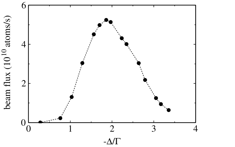
As mentioned earlier, the detuning used in the various stages is the result of a compromise that results from deriving all laser beams from a single source using a very limited amount of AOMs. In Fig. 6 we show the dependence of the beam flux as measured behind the slower mirror on the overall detuning of the dye laser. A fairly sharp maximum appears at , which was consequently chosen as the working point for the setup.
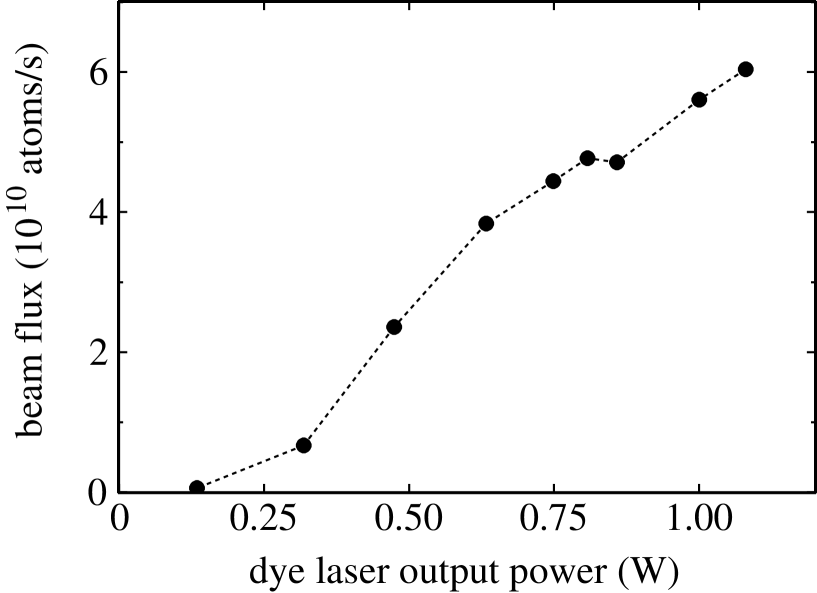
A similar compromise is necessary in order to fix the distribution of optical power over the various cooling stages. In general, all of these show increased performance with the on-resonance saturation parameter up to at least , requiring more than the nominal output of the dye laser to attain everywhere. The distribution of power apparent in Table I is therefore the result of much empirical work. Figure 7 shows the dependence of the output of the beam machine on the total laser power available from the dye laser. The figure shows that the output of the setup increases with laser power in the entire range accessible to us. Consequently, we achieve the maximum beam flux of metastable 20Ne atom/s at the maximum available laser output power of 1W.
B Brightness and brilliance
In the previous sections we showed that, by using several sets of wire scanners, it is possible to measure the characteristics of the atomic beam such as the flux of atoms, the beam diameter and divergence. These quantities can be summarized into values for the brightness , brilliance and reduced phase-space density of the atomic beam. Following Lison et al. [21],
| (5) |
| (6) |
| (7) |
where is the longitudinal velocity spread and the geometric solid angle occupied by the beam, , with and the FWHM transverse velocity spread and average longitudinal velocity of the atoms, respectively [25].
Table II lists measured beam characteristics such as beam flux, beam diameter, longitudinal and transverse velocities, as well as local values of the brightness, brilliance and reduced phase space density calculated from these. Looking at the measured beam flux, going from the collimator to the end of the setup, about a factor of 20 in beam flux is lost. This is mostly caused by the fact that only a small fraction of the slowed atoms can be captured by the magneto-optical compressor, due to its limited spatial capture range in combination with the rather large diameter and divergence of the atomic beam leaving the slower. This effect could be remedied somewhat by using an additional MOL between slower and MOC [3]. Also, experiments show that the slower only slows a fraction of 50% of the atoms that enter it to 100 m/s, probably due to imperfections in the slowing laser’s beam profile as well as imperfect optical pumping into the magnetic sub-level at the start of the slowing process.
The brightness and brilliance of the atomic beam increase drastically going from source to compressor. This is clear from the last three columns of Table II, which give the values of the brightness, brilliance and reduced phase space density at the end of the setup for different operation modes of the atomic beam machine, going from limited operation (source only) to full operation (all laser cooling stages on). Switching on the slower greatly decreases brightness and brilliance due to the increasing beam diameter and divergence; the magneto-optical compressor compensates for this loss. Comparing the operation with only the source on to the full operation mode, we see that the brightness and brilliance increase six to seven orders of magnitude and the phase-space density nine orders of magnitude. Regrettably, the latter is still seven orders of magnitude from the quantum limit .
C Isotope dependence
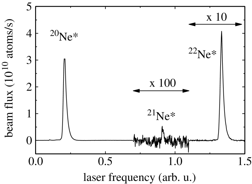
Besides 20Ne there exist two other stable isotopes of neon, the bosonic 22Ne and the fermionic 21Ne, with natural abundance ratios of 20Ne : 21Ne : 22Ne = 1 : 0.0030 : 0.102 [26]. We investigated the achievable beam flux of each of these by scanning the dye laser over a 2GHz frequency range covering resonance lines of every isotope [27] and recording the resulting beam flux. Figure 8 shows the observed signal, with all of the isotopes indeed appearing. From the areas under the appropriate peaks we conclude that the ratios of maximum beam flux are 20Ne∗ : 21Ne∗ : 22Ne∗ = 1 : (0.0011 0.0002) : (0.120.01), not far from their natural abundance ratios. The relatively low output of 21Ne is easily explained by the fact that, due to its hyperfine structure, only part of such atoms can be manipulated at one time (in fact, only the state can easily be laser cooled), while in addition laser cooling for this isotope leads to losses when there is no repumper laser present [18]. In the light of earlier experiments by Shimizu et al [28], who observed that they could not trap 21Ne∗ unless they supplied repumper light, the beam flux we achieve without it is somewhat remarkable. Given the maximum output we obtained with 20Ne, the signals recorded imply that under optimum conditions the setup can deliver a flux of metastable 21Ne atoms/s. In our experience, this is quite sufficient for loading a magneto-optical trap with around fermionic metastable atoms [23]. Of course, this value could easily be increased by using an enriched gas.
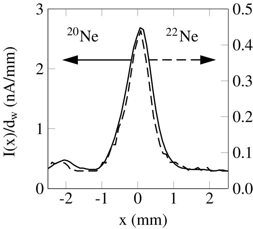
By locking the dye-laser on a saturated absorption signal for 22Ne, we studied the spatial profile of the cold and intense beam of this isotope. As seen in Fig. 9, which shows profiles for both 22Ne and 20Ne measured with the fourth wire scanner, the 22Ne atomic beam has virtually the same width and divergence as the 20Ne beam, and simply contains about seven times fewer atoms than the 20Ne beam.
IV Discussion and conclusions
We have described the implementation of an extensive beam brightening scheme based on manipulation of atomic trajectories by radiation pressure forces. This technique is especially useful for metastable rare gases because of the low efficiency with which these species can be produced in discharge sources. Our setup contains three elements that are essential for reaching very high brilliance: (1) a collimator that increases the atom flux, (2) a slower that reduces both the average velocity and the velocity spread, and (3) a compressor that increases the density by reducing the beam diameter.
The use of each one of these elements with metastable rare gas beams has been reported earlier. In most of these cases, however, emphasis has been on reaching a high flux of slow atoms in order to load a large number of atoms into a magneto-optical trap (MOT). For such experiments, high brightness is not essential so that only a collimator and slower suffice. This combination does not create an atomic beam in the traditional sense of having a small diameter and small divergence, i.e., having high brightness. Precise data on useful flux or brightness produced after slowing have not been published. In this case one could compare MOT loading rates, but this is somewhat out of the scope of the current paper.
In a separate paper [23], however, we will report on loading a MOT with our bright beam. Its small divergence allows us to pass the beam through two 8 mm diameter flow restrictions for differential pumping before entering the trapping chamber, ensuring very low background pressure. The low velocity of the beam makes it possible to slow the atoms down to the capture velocity of the MOT with a 20 mm long Zeeman slower positioned immediately before the trap. In combination with the small diameter of the beam, this results in a very high flux of atoms delivered directly within the spatial capture range of the MOT, which was limited to a diameter of 18 mm by the size of the trapping beams that we used. We have observed MOT loading rates of up to 3.6 atoms/s, constituting nearly 65% of the total beam flux. Because of this high efficiency, we are able to trap up to 9 metastable 20Ne atoms and 3 metastable 22Ne atoms in our MOT under otherwise conventional trapping conditions. These numbers are substantially higher than reported by others [4, 13, 29, 30] for brightened but not compressed metastable atomic beams.
Applications where high brightness as afforded by the use of a MOC is clearly profitable, e.g., atom lithography, certain quantum optics experiments and loading hollow fiber guides, have been reported by Engels et al [9], Koolen [3] and Dall et al [11, 31], respectively. In the latter two cases, the experimental setups used are based on virtually the same ideas as ours but use helium as the rare gas. The difficulties of manipulating helium, with its comparatively small linewidth, have led to beam fluxes that are smaller by a factor of 6 to 10 [3, 11, 31]. Dall et al report a final beam diameter of around 5 mm, suggesting a much smaller brightness was achieved but final data on this is lacking. Koolen’s setup produces a brightness of 1.0 s-1m-2sr-1, quite comparable to our result. Engels et al, who also use neon, report a beam flux of atoms/s, which is two orders of magnitude less than our current values, mostly due to the use of a less efficient collimator. Since, however, these authors achieved a much smaller beam diameter (m) than we do as well as somewhat smaller divergence, their setup delivers a factor 3.3 higher phase space density and a factor 2.3 higher brilliance.
For alkali-metal beams, the highest brightness, 6.3 Cs atoms s-1m-2sr-1 has been reported by Lison et al [21]. Their setup uses a combination of a collimator, a slower and a lens plus re-collimator to produce a flux of Cs atoms/s. Comparing these numbers to our own, we find that they are nearly the same, notwithstanding the fact that we are forced to start out with a much lower brightness atom source. This again points out that very large gains in output are possible with beam brightening techniques which depend to a large degree on the efficiency of the collimator used.
Finally, there is still room for improvement of our results. For one, the use of a magneto-optic lens between slower and compressor could increase the final beam flux by a factor of by effectively increasing the capture range of the compressor [3]. Also, outside of the region of strong Stern-Gerlach forces, sub-Doppler transverse cooling of the bright beam is possible in principle. Given the limits of such cooling mechanisms [18], a FWHM divergence of 2.4 mrad can be achieved leading to a gain in both brightness and brilliance of another factor of 10.
V Acknowledgments
We are indebted to J.T.M. van Beek, W.J. Mestrom, V.P. Mogendorff, S.J.M. Kuppens, B.J. Claessens, and E. van Kempen for help with some of the experiments, to K.A.H. van Leeuwen for many helpful discussions, and to M.J. de Koning, L.A.H.M. van Moll and J.A.C.M. van de Ven for technical assistance. We thank A.E.A. Koolen for pointing out the effects of the Stern-Gerlach force to us. This work was supported by the Netherlands organization for Fundamental Research on Matter (FOM) and by the Royal Netherlands Academy of Arts and Sciences (KNAW).
REFERENCES
- [1] B. Brutschy and H. Haberland, J. Phys. E 10, 90 (1977).
- [2] M. Hoogerland et al., Appl. Phys. B 62, 323 (1996).
- [3] A. Koolen, Ph.D. thesis, Eindhoven University of Technology, (2000); see also R.M.S. Knops et al, Laser Phys. 9 (1999) 286.
- [4] F. Shimizu, K. Shimizu, and H. Takuma, Chem. Phys. 145, 327 (1990)
- [5] A. Aspect et al., Chem. Phys. 145, 307 (1990)
- [6] A. Scholz et al., Opt. Commun. 111, 155 (1994)
- [7] J. Nellessen, J. Werner, and W. Ertmer, Opt. Commun. 78, 300 (1990).
- [8] M. Schiffer, M. Christ, G. Wokurka, and W. Ertmer, Opt. Commun. 134, 423 (1997)
- [9] P. Engels et al., Appl. Phys. B 69, 407 (1999)
- [10] D. Milic, M. Hoogerland, K. Baldwin, and S. Buckman, Appl. Opt. 40, 1907 (2001).
- [11] R. Dall, M. Hoogerland, K. Baldwin, and S. Buckman, J. Opt. B 1, 396 (1999)
- [12] W. Rooijakkers, W. Hoogervorst, and W. Vassen, Opt. Commun. 123, 321 (1996)
- [13] N. Herschbach, P. Tol, W. Hogervorst, and W. Vassen, Phys. Rev. A 61, 050702 (2000)
- [14] P. Tol et al., Phys. Rev. A 60, R761 (1999)
- [15] E. Rasel et al., Eur. Phys. J. D 7, 311 (1999)
- [16] G. Labeyrie et al., Eur. Phys. J. D 7, 341 (1999)
- [17] S. Nowak et al., Appl. Phys. B 70, 455 (2000)
- [18] H. Metcalf and P. van der Straten, Laser cooling and trapping (Springer, New York, 1999).
- [19] B. Sheehy, S. Shang, P. van der Straten, and H. Metcalf, Chem. Phys. 145, 317 (1990).
- [20] W. Phillips and H. Metcalf, Phys. Rev. Lett. 48, 596 (1982)
- [21] F. Lison, P. Schuh, D. Haubrich, and D. Meschede, Phys. Rev. A 61, 013405 (1999).
- [22] H. Hotop, in Atoms and Molecules, Vol. 29b of Atomic, Molecular and Optical Physics (Academic Press, New York, 1996), p. 191.
- [23] S. Kuppens et al., Phys. Rev. A, submitted for publication
- [24] R. Stas, Master’s thesis, Eindhoven University of Technology, 1999 (unpublished)
- [25] In the formulas we give here several factors of 2 appear compared to those in Ref. [21] because we define spatial and velocity spreads in terms of their FWHM rather than HWHM values.
- [26] D. R. Lide (ed), CRC Handbook of Chemistry and Physics, 72nd ed. (CRC Press, Boca Raton, 1991).
- [27] L. Julien, M. Pinard, and F. Laloe, J. Phys. (Paris) Lett. 41, L479 (1980)
- [28] F. Shimizu, K. Shimizu, and H. Takuma, Phs. Rev. A 39, 2758 (1989)
- [29] A. Robert et al., Science 292, 461 (2001)
- [30] F. D. Santos et al., Eur. Phys. J. AP 14, 69 (2001)
- [31] M. Hoogerland, private communication.
| Component | a | ||||
|---|---|---|---|---|---|
| (mm) | (mm) | (mW) | |||
| nozzle source | 0 | ||||
| collimator | 43 | 150 | b | 1.6 | +8 |
| 1st wire scanner | 210 | ||||
| 1st Doppler cooler | 230 | 50 | 50 | 3.0 | -1.8 |
| beam stop | 300 | ||||
| flow restriction | 390 | 100 | |||
| 2nd wire scanner | 790 | ||||
| 1st Zeeman solenoid | 1230 | 850 | 100 | 2.6 | -50 |
| 2nd Doppler cooler | 2260 | 40 | 40 | 0.5 | -1.8 |
| 2nd Zeeman solenoid | 2370 | 150 | 100 | 2.6 | -50 |
| MOC | 2670 | 90 | 250 | 1.9 | -1.8 |
| 3rdwire scanner | 2800 | ||||
| 4thwire scanner | 2950 | ||||
| slower mirror | 3000 | ||||
| beam flux detector | 3320 |
| stage | |||||||||||
|---|---|---|---|---|---|---|---|---|---|---|---|
| mm | /s | mm | m/s | m/s | (s m2sr) | (s m2sr) | 10-13 | ||||
| source | 0 | 2600 | 0.15 | 480 | 580 | 130 | 1250 | 580 | 4 | 2 | 3 |
| collimator | 210 | 110 | 9 | 480 | 11 | 0.42 | 4.0 | 1.9 | 1 | 5 | 9 |
| 1st Doppler cooler | 790 | 110 | 15 | 480 | 4.8 | 0.79 | 7.6 | 3.5 | 3 | 1 | 2 |
| Zeeman slower | 2800 | 55a | 30a | 98 | 2.0a | 0.01 | 0.26 | 70 | 1 | 1 | 1 |
| MOC | 2800 | 4.8 | 0.72 | 98 | 0.84 | 21 | 500 | 1.3 | 1 | 1 | 1 |